76 L82 Corvette 355 engine build questions

76GrayVette said:
Thanks Grumpy, so I guess they are supposed to be left on then. It seems like they would melt.

Yep, those are Brodix Indy, the IK180

I know some guys leave them , and I have never heard of it causing ill effects ,I suspect they are designed to melt and dissolve in hot oil, and I know guys remove them, personally Ive always removed them them, simply because I know what they were there for, a reminder NOT to screw up and overlap the ends of the expander spring
 
Hey guys.
I'm working on checking the oil pump screen to pan clearance and I was wondering where I measure from. The flat part or the lip of the screen. On my screen the flat part is closer to the pan than the lip of the screen.
oilpumpscreen.jpg


Also, I'm getting ready to check my pushrod length and piston to valve clearance but I'm using hydraulic lifters. I read on one of your posts grumpy where I thought it said I could use an old lifter or an extra lifter and fill it will epoxy so that it won't compress when I'm checking. Is this correct or am I way off?
 
oilpumpscreenA.jpg

that oil pump pick-up is designed to in theory prevent or limit oil pump oil flow starvation when or if surface A comes to rest on the oil pan floor as surface B should in theory be prevented from coming in contact with ,or too close too the oil pan floor to restrict the flow into the oil pump, in reality your still best served by keeping surface A at least 1/4" off the oil pan floor and brazing the oil pump pick-up too the pump, to prevent it vibrating loose.

READ THESE LINKS
USE A SOLID LIFTER and MODELING CLAY TO CHECK PISTON TO VALVE CLEARANCE
http://www.jegs.com/i/Crower/258/66900- ... 0000599820
ChvyLifterXLa.gif

a single chevy solid lifter youll use for testing valve to piston clearance generally costs under $10 at a local auto parts
there should be and arts/crafts store near you where you can purchase a one lb pack of plastic modeling clay for measuring clearances, I know I buy a pound of it every 6-9 months for that reason
large-van_aken_plastalina_clay.jpg


TW-383-oil-pump-5.jpg


vcl2.jpg

vcl3.jpg

vcl4.jpg


viewtopic.php?f=52&t=399

viewtopic.php?f=54&t=1800
 
yes it would function just the same if it was done correctly, its just a bit easier to keep a lifer that's obviously a bit different in appearance separate in your cam degree in kit, with less chance of it getting misplaced.
I filled one with J&B weld years ago for just that purpose and used it untill it "disappeared" after I lent my cam degree in kit to a buddy
 
Okay, I just ran into another problem I think. I looked at my heads spring pressure and it says they are closed 100 and open 320. My cam card shows spring requirements to be seat 114 and open 303. This is not good right?
I looked up the part number of the springs recommended on the cam card and they have an outside diameter of 1.255 which is bigger than the springs on my heads. They are only 1.250.
I need to get different springs correct?
Head springs
WP_20140610_007.jpg


Cam spring requirements
WP_20140610_008-1.jpg
 
76GrayVette said:
Okay, I just ran into another problem I think. I looked at my heads spring pressure and it says they are closed 100 and open 320. My cam card shows spring requirements to be seat 114 and open 303. This is not good right?
I looked up the part number of the springs recommended on the cam card and they have an outside diameter of 1.255 which is bigger than the springs on my heads. They are only 1.250.
I need to get different springs correct?
Head springs
WP_20140610_007.jpg


Cam spring requirements
WP_20140610_008-1.jpg

thanks I needed that! I got a good laugh!
the truth is that in about 99% of the cases if you have an accurate valve spring measuring load rating tool most valve springs (about 95%)will be within about 5% of the listed load rates as they come out of the box, now think about that a second...5% of a valve spring rated at 320lbs , basically means about a 16 lb variation and remember the installed height and shims or stacked shims can be adjusted to increase or loosen the installed height a bit to reduce the valve spring pressure , so if lets sat the installed height is supposed to be 1.900 and closed seat 114 open 303 and your installed height is the same with that closed 100 and open 320 load rating your still well with-in the ball park, but obviously the smart thing to do would be to check with both the cam manufacturer and your local machine shop, but be aware that theres a strong incentive to sell you parts you may or may not need , personally Id strongly suspect that your so close in all specifications that as long as your no where near having clearance issues like spring bind, that the minor differences in load rates on those springs or the totally meaningless difference in outer spring diameter , can be ignored here., but as always to feel like your safe check with the cam manufacturer, who I'm sure will tell you you need to buy and install his springs, lifters and all matched valve train components in order to have his warranty apply , but if you go that route and if you get the chance check, the difference in the valve spring load rates, you might be surprised to find out, that in many cases your swapping out identical springs
A VALVE SPRING LOAD TESTER IS EXPENSIVE, BUT A GREAT TOOL TO HAVE
vsts1.jpg

http://streetperformanceusa.com/i-72754 ... ester.html
vsts2a.jpg

http://www.summitracing.com/parts/pro-66775
vsts3.jpg

http://www.summitracing.com/parts/pro-66776/overview/
 
Right, thanks grumpy. I was just worried the heads had too much spring pressure for the cam, but I guess it's not that sensitive to the amount of difference that the specs are showing.
 
How much radial clearance do you recommend for the valves?
I've read several links that you had posted and they all say a minimum of 0.050" radial valve clearance but the AFR website says something about a 0.200" radial clearance around the perimeter of the valve.
Which is correct?
 
.050 is minimal for mechanical interference,obviously more is better, .200 is minimal distance to a cylinder wall or chamber wall for air flow restriction,and ideally you want as much room as you can get , obviously one results in damage the other results in power potential dropping off , but keep in mind radial edge interference tends to be minimal on air flow
rectvsoval.jpg

heres two of the few side-by-side closed chamber vs open chamber pictures I have,they found by laying back the combustion chamber wall air flow rates sand cylinder scavenging efficiency increased at upper rpms and power went up, noticeably after 5000rpm due to the increased air flow and cylinder scavenging

flowsz1.png

combustionchamberflow.jpg

Valvesshroud.jpg

swirlpic.jpg
 
Which break-in oil do you guys recommend?
I was thinking about using Royal Purple break-in oil but wanted to double check and hear if anyone had any experience with it.
 
http://www.gmpartsdirect.com/results.cf ... number=EOS

GM EOS is available as is crower zddp
FRICTION REDUCING OIL SUPPLEMENTS

http://www.summitracing.com/parts/CRO-86092

I usually use 6-7 quarts of oil and 1 quart of marvel mystery oil added in my oil pan 11 quart oil pan and oil cooler system capacity
10W30 Valvoline VR1 Conventional Racing Oil
10W30 Valvoline NSL
10w30 Castrol GTX conventional,
10w30 mobile 1
10w30 KENDAL racing oil


related threads

viewtopic.php?f=52&t=282

viewtopic.php?f=50&t=798&p=1160&hilit=erson+break+in#p1160

viewtopic.php?f=52&t=10182&p=40244#p40244

viewtopic.php?f=52&t=1489&p=3360&hilit=erson+break+in#p3360

viewtopic.php?f=53&t=6352&p=39548&hilit=assembly+lube#p39548
 
grumpy you think theres any benefit to adding some of that stuff to a motor with roller lifters? or is it really just to save flat tappets?
 
rolling friction and sliding surface contact friction are two different ball games, , while I doubt adding a friction reducing oil additive has as great of added benefit in a roller lifter equipped engine, compared to a flat tapped cam engine you must keep in mind theres still plenty of non roller contact friction points in a roller lifter equipped engine, like bearing surfaces, timing chains, valve guides etc. so adding some friction reducing oil additive will more than likely still help reduce wear .


ISKY CAMS Tech Tip

Roller Lifters: Keep 'Em Rolling Longer

Most racers are aware of the advantages of Roller Lifters. For those who are not, a brief review is in order. Roller Cams & Lifters are employed today in all-out racing engines where valve lift/area requirements preclude the possibility of employing a flat tappet (solid lifter cam). Higher Lift requires higher valve spring loads (pressures) and flat tappet cams can only handle so much. Additionally, increased rates of lift (cam lobe velocity) above .007" per degree for example on an .842" diameter G.M. lifter, would cause the lobe to reach-out over the edge of the lifters' cam face. Consequently, with either too much spring or too high a lift rate, most racers know that extremely radical flat tappet cams will eventually self-destruct.

But, what about Roller Lifters? Are they as indestructible as many believe? How do we prolong the life of their roller bearings in today's modern race only engines? Roller lifters require special care and maintenance if they are to provide good service life. Here are the 4 most important factors you should consider to insure their success.

1. AVOID DRY "START UP": Roller Lifter Bearings are assembled with a "tacky" rust-preventing grease that is not intended for lubrication. Therefore, new lifters should have their roller bearings thoroughly washed in clean solvent or acetone to completely remove this assembly grease. After air drying, premium motor-oil (non-synthetic) such as Penzoil SAE 25W50 GTP Racing Oil (The best of the mineral based oils) or Amzoil "Red" Racing Oil (synthetic) should be used to pre-lube the bearings just before installation.

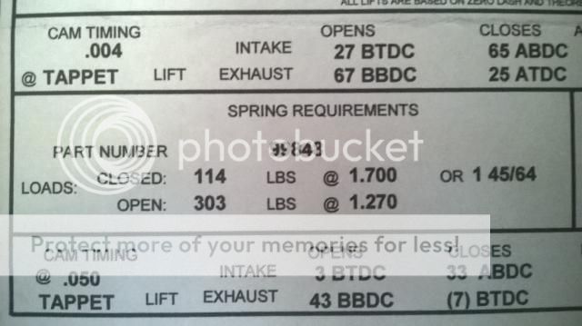
2. AVOID "OVERLOAD": Increased load always means reduced service life. Want 50% more thrust from a jet engine? Ask Rolls Royce or G.E. and they'll tell you to expect about ¼th the service life between overhauls. Similarly, employing drag race valve springs in the 900, 1000 to 1100 lb. Range will reduce the life of your roller bearings between rebuilds much the same as will employing high-impact roller cam profiles.

3. EMPLOY A REV KIT WHEN POSSIBLE: The primary advantage of Camfather Ed Isky's invention of the 1950's is that by pre-loading each Roller Lifter Bearing to its respective cam lobe, you eliminate needle roller bearing "skew". Skewing (the momentary mis-alignment of the bearings' needle rollers to their respective races) is provoked by the start-stop skidding action of the roller bearings each time the lash is taken-up. Eliminate it and you extend roller bearing life dramatically! Unfortunately, many engines such as the Big Block Chevy which could use one the most, don't lend themselves to such an installation because of the severe angularity of the pushrod coming out of the lifter.

4. EMPLOY LIFTERS WITH "PRESSURE-FED" OIL TO THE NEEDLE ROLLER BEARINGS: Hope is a good thing. But hoping oil will eventually find its way to your Roller Lifter bearings is not. Unfortunately, most roller lifters on the market do not pressure feed oil to the needle rollers, depending on the "splash & a little luck" system instead. In contrast, all Isky Roller Lifters feature pressure fed oil to their roller bearings. Isky's Top of the line "Red Zone" Series lifters feature an exclusive 3-Point "Multi-Port" oiling system to constantly bathe the needle rollers with cooling lubrication. Additionally, they feature our famous Marathon Roller bearing with the toughest shock absorbing heavy duty outer bearing race on the market for the highest possible load carrying capability and sustained Hi-Rpm Endurance. And, they're fully rebuildable, making them your best long-term value!
 
Well, I got the engine back in my car and went through the break in process. I think I did everything right but I have this tapping noise that is coming from cylinder #3 and I'm not sure what it is. I removed the guide plates on that cylinder and took the lifters out to inspect the cam lobes.I'm not sure if it's good or bad. It doesn't look like the surface is uneven really, but it has that dark hemisphere on either side of the lobe. I also checked cylinder #1 and the lobes there look the same. Compression is even on both and several others I checked. Any ideas of what could be going on?
Here's the exhaust lobe on cylinder #3. The bright reflection is the very top of the lobe point. The lifter faces all look smooth.
WP_20140626_006.jpg
 
I might be wrong but at least in what I can see in the picture it appears the lobes starting to wear excessively, why not look at the base of that lifter compared to a similar lifter , I think youll see more evidence, and if it is Id go back and re-check all the valve train clearances very very carefully before tying to break in the next cam, because if somethings binding it will just repeat endlessly untill the clearance issues corrected
worn1a.jpg
 
I asked Crane's tech department and they said that both the lobe and lifter looked fine. I'm unsure as to whether or not to believe them though.
Here's what the lifter looks like Grumpy. The four that I pulled still look very smooth and convex.
Here's the lifter that was run on the left and a new, unused Crane lifter on the right.
IMG_0850.jpg

This is the used lifter
IMG_0858.jpg

Here's another angle of one of the cam lobes. The opening ramp is visible here.
IMG_0869.jpg

Also, I don't know if it means anything or not, but my old stock cam had the same marks on every lobe, just not as severe.
IMG_0875.jpg


What do you think?
 
the base of the lifter ,picture you posted looks ok, but since your getting a tapping ,valve train noise issue, I'd try swapping BOTH the rockers from #3 to #8 , and #8 rockers to #3 or at least some location on the other cylinder bank to find out if the tapping noise moves with the rockers or stays with the #3 cylinder
 
Back
Top