You are using an out of date browser. It may not display this or other websites correctly.
You should upgrade or use an alternative browser.
You should upgrade or use an alternative browser.
My Cam Research for the Experts Eye
- Thread starter TXChevy
- Start date
I'll double check, Rick. I think it's pretty smooth, maybe just the picture but a good point.
Now that I'm thinking about it, I'll check the seal surface where it contacted the sleeve.
I'll be out of town this week, so it'll be the weekend before the saga continues ....
Before I head out, more pics....
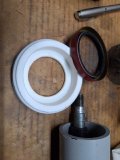
The National seal I removed
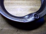
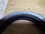
And the new seal I had....
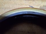
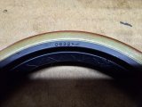
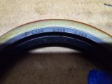
I take it that in the picture above it's designed for a 2.328" OD shaft. Note that in my case, with the sleeve, the OD is 2.360" meaning that the seal should be tighter. The old seal wasn't burned, the engine has only been run about 3 hrs so far.
I looked up CHO seals, it's a Chinese seal. I ordered a GM and an SKF seal to compare them.
Now that I'm thinking about it, I'll check the seal surface where it contacted the sleeve.
I'll be out of town this week, so it'll be the weekend before the saga continues ....
Before I head out, more pics....
The National seal I removed


And the new seal I had....


I take it that in the picture above it's designed for a 2.328" OD shaft. Note that in my case, with the sleeve, the OD is 2.360" meaning that the seal should be tighter. The old seal wasn't burned, the engine has only been run about 3 hrs so far.
I looked up CHO seals, it's a Chinese seal. I ordered a GM and an SKF seal to compare them.
Last edited:
They do make other size seals that might fit the sleeve better. You will notice the part number 3945 below is for a shaft diameter of 2.330". Lots of technical info in the catalog link below.


The sleeve should have a surface finish of 10 to 20 microinch. Surely you have a tool to measure this with???
Fast, Inexpensive Shaft Repairs
Timken’s line of Redi-Sleeves are easy to install and feature
a removable flange and an installation tool. When using
Redi-Sleeves, you receive:
• Strong, durable stainless steel construction that provides a
corrosion-free sealing surface
• Ultra-thin construction that allows original seal size to be
used with minimal additional lip loading
• Redi-Sleeve sealing surfaces that are ground to a 10-20 microinch
Ra (0.25-0.50 Micrometer Ra) finish without lead
• Options for shafts from 0.5" (12.7mm) to 8" (203mm) diameters
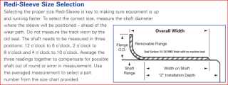
.


The sleeve should have a surface finish of 10 to 20 microinch. Surely you have a tool to measure this with???
Fast, Inexpensive Shaft Repairs
Timken’s line of Redi-Sleeves are easy to install and feature
a removable flange and an installation tool. When using
Redi-Sleeves, you receive:
• Strong, durable stainless steel construction that provides a
corrosion-free sealing surface
• Ultra-thin construction that allows original seal size to be
used with minimal additional lip loading
• Redi-Sleeve sealing surfaces that are ground to a 10-20 microinch
Ra (0.25-0.50 Micrometer Ra) finish without lead
• Options for shafts from 0.5" (12.7mm) to 8" (203mm) diameters

.
Attachments
It was just looking at that same online catalog! Also trying to sort through the various selections. I need to go back and see which sleeve I used - as I recall I simply picked one for MK IV 454 stock balancer. I think it was SKF but I can't check right now. Not a sleeve/seal kit, just the sleeve.
Lol nope I can't check the surface
Lol nope I can't check the surface
Whilst on our small trip I've thought about this leak. I wonder if this is getting overcomplicated. Seems that thousands of sleeve/seal repairs are made without issue. I may be going down extra rabbit trails trying to figure out appropriate repair.
I made a couple of assumptions earlier.
- oil pan gasket wasn't the source. Right now based on leak symptoms I'm leaving that alone.
- seal spring retainer was intact. But now I'm not sure as it was separated from the seal when I pulled it. So the question is was it loose before I removed the seal or even with the care I used it came loose? Don't really know to tell the truth.
The steadily increasing leak could indicate the spring coming loose, leaving only the rubber against the sleeve. Even with the removed seal distortion I had to expand the spring a bit to reinstall it. Under a magnifying glass, the rubber lip looked fine, not damaged, so I think the sleeve surfacing is fine.
If the overall installed seal compression is around. 050", this should be more than enough for oil retention and for any slight seal misalignment.
So my plan is to get the 2 new seals and compare their IDs. Select one to install, reinstall the balancer and see what happens. New seal will be installed using the harmonic balancer installer, I'll use some sort of open pipe to push the new seal in without hammering.
I may be able to find a double lip seal but really, I should be able to use a standard balancer seal.
Since the spring was there when you installed the seal, my bet is it was fine and only came off when you removed the seal.- seal spring retainer was intact. But now I'm not sure as it was separated from the seal when I pulled it.
You don't say, but it looks like you put a sealer between the crank snout and balancer ....... right? All you can do at this point is replace the seal, going further would be alot of work. If this doesn't fix the problem, then you can go back and think about the timing cover and oil pan. Not what anyone wants to do, but what options do you have!
Can you put the radiator back with just a few fasteners and run the engine for a short time, then use a bore scope to look behind the balancer?
Yes I had a thin wipe of permatex on the crank/keyway. No oil seepage to the front of the balancer.
It's pretty straightforward to install/pull the radiator. Fan assembly goes in first. I'll probably just put everything back together and cross my fingers. Otherwise even if no leak I'd be draining coolant again to pull the radiator to install fans.
Yup I used my borescope to check it all out the first time. I'll do the same again.
I spent some time to look at different seals, dimensions, etc.
In the end I reverted to installing the same National 3945 seal. I did get an SKF 21771 seal, but it's a tight fit on a balancer without a sleeve, no way it fits on my balancer with the sleeve. The ID of the SKF seal is 2.145".
And with all the documentation I do, I can't find a record of what sleeve I used (Timken or SKF). But in either case, they note that the original balancer seal can be used.
Incidentally, I've linked to the SKF seal catalog, may be of some interest:
SKF Seal Catalog
The OD of the balancer with sleeve is 2.360".
The new National 3945 seal has an ID of 2.245" (measured with my digital caliper) and is supposed to be for shaft size of 2.330". This 3945 is listed for pretty much any 70's/80's truck with a 454.
So doing some math, if the 3945 installed on a shaft of 2.360" and it has an ID of 2.245", that equals overall compression of .115", or a circumference compression of .0575". This should be more than enough to ensure a good grip seal-to-sleeve. Anything more and I'd be concerned about the rubber seal overheating, even with the oil bath (cooling) it receives. Subjective feel of the seal onto the sleeve seems good, not too tight but definitely a positive compression.
Rather than beat the seal on with a hammer, I made an "installer" - not fancy but it should get the job done. It uses the harmonic balancer install tool to compress the seal into the timing cover. That threaded part is a pvc cap for 3" pipe, I just cut the center out of it - it has a nice flat ledge to push against the seal frame. I'll post a picture of it all in place as the seal is being installed.
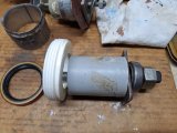


Did you read pages 21 thru 23 of the SKF catalog? I don't remember how deep the groove was on your balancer from seal wear, but I found this interesting.
5 -If the shaft is deeply scored, fill the
groove with a powdered metal
epoxy-type filler. Install the sleeve
before the filler hardens, enabling the
sleeve to expel any excess filler. Clean
away any remaining filler from the
sleeve outside diameter surface.
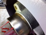
I'm wondering if the sleeve had some burrs on the leading edge that left some very small cuts in the seal lip. Maybe too small to see during inspection after you pulled the seal. Consider polishing the leading edge with some 2500 grit paper before installing the balancer.
.
5 -If the shaft is deeply scored, fill the
groove with a powdered metal
epoxy-type filler. Install the sleeve
before the filler hardens, enabling the
sleeve to expel any excess filler. Clean
away any remaining filler from the
sleeve outside diameter surface.
I'm wondering if the sleeve had some burrs on the leading edge that left some very small cuts in the seal lip. Maybe too small to see during inspection after you pulled the seal. Consider polishing the leading edge with some 2500 grit paper before installing the balancer.

.
Excellent suggestion, I'll do that.
Close observation of the old seal didn't seem to find any lip issues, it's not just the main lip edge but there's also a tiny extra thin ridge running along that lip. All appeared to be ok, but I still can't say for 100% the backup spring was ok.
I did see that in the catalog - in my case there was only a very slight mark on the balancer. No deep groove. Sleeve installation was more of a "just to be sure" than a real requirement.
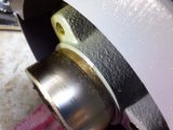
Here's another view of the sleeve, I'll give the leading edge a slight polish. It actually has a slight inward lip.
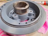

The seal lip diameter is small enough that it's going to compress onto the crank leading edge and then over the sleeve leading edge. Do you have something similar to the plastic sleeve used for intake/exhaust valve installation, only sized for the balancer. I'm thinking something like plastic wrap used in the kitchen. Only problem is accessibility to remove the plastic wrap after the balancer start thru the seal. Just throwing some ideas out there. Probably over thinking this???I'll give the leading edge a slight polish. It actually has a slight inward lip.
I considered that but in my test fit of the seal, there didn't seem to be any issue with the seal lip hanging up. I will still polish out the leading edge of the sleeve and add a good film of assembly lube on all surfaces.
I installed the seal today, it went good. I also checked the centering of the timing cover around the crank, the gap was even all the way around.
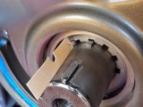
This is the area that I'll pay close attention to when I run the engine. I will try to secure my borescope camera on this.
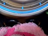
My benchtop install tool worked well, I'm very happy with it. I could shift it slightly as needed to be sure the seal was evenly installed. I did add a very thin smear of Permatex #2 to the seal frame, something I do on every seal. No hammering needed, but I still checked the spring with a light and a small mirror.
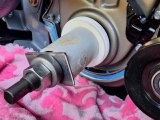
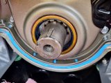
I hope this works or it's the oil pan next and I hate thinking about that one....
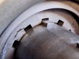
Something I noticed is that the key is about halfway into the cam gear slot. I know that the balancer also clamps tightly against the gear but I wish it was a full fit. Oh well - I guess if that gear shears the key there's a bigger problem that caused it!
I installed the seal today, it went good. I also checked the centering of the timing cover around the crank, the gap was even all the way around.

This is the area that I'll pay close attention to when I run the engine. I will try to secure my borescope camera on this.

My benchtop install tool worked well, I'm very happy with it. I could shift it slightly as needed to be sure the seal was evenly installed. I did add a very thin smear of Permatex #2 to the seal frame, something I do on every seal. No hammering needed, but I still checked the spring with a light and a small mirror.


I hope this works or it's the oil pan next and I hate thinking about that one....
Something I noticed is that the key is about halfway into the cam gear slot. I know that the balancer also clamps tightly against the gear but I wish it was a full fit. Oh well - I guess if that gear shears the key there's a bigger problem that caused it!

Installed the balancer today. I did a test fit of the other (China) seal only to see what the lip did as it went over the sleeve.
No real drama, the sleeve has a curved top end, the seal very smoothly slid over that lip. The sleeve itself is very smooth, I think if I tried x000 grit wet sanding, I would wreck the finish, so I left it alone.
Top of sleeve, you can see the curved end. That's a bit of sealer showing at the end of the sleeve.
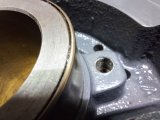
Seal at the curved end of the sleeve, there's no hang-up.
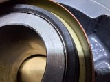
Seal installed over the sleeve, no issue. The National seal I've installed has a better grip on the sleeve, but I had test-fit it before installing it into the timing cover, also no problem.
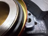
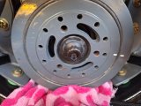
Balancer fully seated on the crank (using the proper install tool). You can see a small bit of Permatex #2 that has seeped out around the perimeter and the keyway. I usually put an extremely light touch of P#2 on the crank and then a very moderate wipe in the keyway. The prior oil leak was not from these areas.
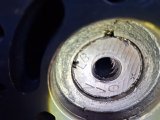
ARP crank bolt torqued to spec.
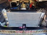
Fans and radiator back in place.
So now it's just putting the coolant back in and firing it up.
Place your bets ........
No real drama, the sleeve has a curved top end, the seal very smoothly slid over that lip. The sleeve itself is very smooth, I think if I tried x000 grit wet sanding, I would wreck the finish, so I left it alone.
Top of sleeve, you can see the curved end. That's a bit of sealer showing at the end of the sleeve.

Seal at the curved end of the sleeve, there's no hang-up.

Seal installed over the sleeve, no issue. The National seal I've installed has a better grip on the sleeve, but I had test-fit it before installing it into the timing cover, also no problem.

Balancer fully seated on the crank (using the proper install tool). You can see a small bit of Permatex #2 that has seeped out around the perimeter and the keyway. I usually put an extremely light touch of P#2 on the crank and then a very moderate wipe in the keyway. The prior oil leak was not from these areas.

ARP crank bolt torqued to spec.

Fans and radiator back in place.

So now it's just putting the coolant back in and firing it up.
Place your bets ........
Just to be dang sure there's no internal pressure issues, before I start the engine again, I'm installing a new PCV valve. The one on the car seems to be just fine, you can clearly hear the checkball in it, but for a few bucks I'll start with a new one. One valve cover has the PCV routed to carb base (full vacuum), the other valve cover has a breather.
I've not yet run the engine, been a bit busy, but I will in the next day or so.
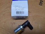
I've not yet run the engine, been a bit busy, but I will in the next day or so.

Happy New Year friends 
I posted an update on the transmission rebuild, but I'll be focusing a bit more on the car. I need to have a "drive ready" vehicle for the transmission.
Key focus:
- shifter installation
- functional brakes
- driveshaft installed
- trans cooler/lines installed
- minor mod to crossmember
First up, I ran the engine today for the first time since new balancer seal installation. So far, so good. I put a piece of manilla folder under the balancer and it's stayed clean. Still holding my breath though, lol
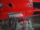
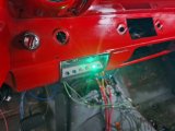
I also wanted to show function of the indicator panel I had mentioned earlier.
Fuel pump off
Fuel pump on
Fans on, fuel pump on
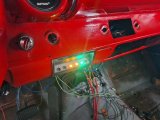
The other 2 indicator lights aren't connected yet (line lock, th400 downshift). I know - not everybody's cup of tea, but it works for me as an easy visual of what's going on. Lights are visible but not as glaring as the camera shows.
Next up are brakes, which are already installed, but still a dry system.. I bled the master cylinder on the car - as you can see I'm using Dot5 (silicone) brake fluid.
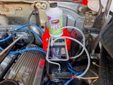
MC bled, hoses full of fluid, no more bubbles. Took about half an hour of a combo of slow pedal pushes, letting it sit for a few minutes, then repeat. That seems to work for Dot5, which for me has been a bit fiddly to bleed.
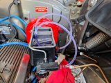
Stopped here to chase down a leaky flare fitting downstream. Gotta fix that plus any others before I can get the wheels bled.

I posted an update on the transmission rebuild, but I'll be focusing a bit more on the car. I need to have a "drive ready" vehicle for the transmission.
Key focus:
- shifter installation
- functional brakes
- driveshaft installed
- trans cooler/lines installed
- minor mod to crossmember
First up, I ran the engine today for the first time since new balancer seal installation. So far, so good. I put a piece of manilla folder under the balancer and it's stayed clean. Still holding my breath though, lol

I also wanted to show function of the indicator panel I had mentioned earlier.
Fuel pump off

Fuel pump on

Fans on, fuel pump on

The other 2 indicator lights aren't connected yet (line lock, th400 downshift). I know - not everybody's cup of tea, but it works for me as an easy visual of what's going on. Lights are visible but not as glaring as the camera shows.
Next up are brakes, which are already installed, but still a dry system.. I bled the master cylinder on the car - as you can see I'm using Dot5 (silicone) brake fluid.

MC bled, hoses full of fluid, no more bubbles. Took about half an hour of a combo of slow pedal pushes, letting it sit for a few minutes, then repeat. That seems to work for Dot5, which for me has been a bit fiddly to bleed.

Stopped here to chase down a leaky flare fitting downstream. Gotta fix that plus any others before I can get the wheels bled.

