renegade intake? for cross fires

I don't mean to be A Drill Sargent US MARINE CORP STYLE.....But these 700R4 Transmissions are unforgiving if shortcuts are taken Gibbles.

I am patient.
I will check in often as I can to help you.
 
For reference a nice clutch apply chart I found, much better than what's in my manual..
upload_2016-6-3_8-27-48.png
Here are some images I took... for those that have not seen inside of a trans.

basic stack in order (top of stack is the rear of the transmission)
Bottom cage looking thing is the sunshell
upload_2016-6-3_8-29-58.png

All of that love sticks down in here, top goes in first...
at the bottom of the transmission you can see the low reverse piston and spring cage.
Note the parking prowl
upload_2016-6-3_8-31-1.png

First piece in, note the position of the parking prowl
upload_2016-6-3_8-33-2.png

Next piece in, the rear planetary gear set

upload_2016-6-3_8-33-48.png
 
Next pieces, the low reverse clutch pack

upload_2016-6-3_8-34-47.png

Next piece, the rear case support, also houses the low reverse sprag/roller clutch

upload_2016-6-3_8-35-59.png

Image missed the rear sun gear inserts down in the center
 

Attachments

  • upload_2016-6-3_8-37-11.png
    upload_2016-6-3_8-37-11.png
    501.5 KB · Views: 2
Input drum assembly sits down on top...

Teflon seals, I picked up a little tool off of ebay, however I expected something slightly different...

Here are the Teflon seals being expanded prior to install...

upload_2016-6-3_8-42-13.png

Installed on the turbine shaft... now they need to be resized again...
upload_2016-6-3_8-42-58.png

A little trick I picked up, use electrical tape to resize, trick here is to stretch the tape until it's almost ready to break, and keep wrapping it while working the seal with your fingers to help it shrink...

upload_2016-6-3_8-44-16.png

Same on the pump stator shaft
upload_2016-6-3_8-44-53.png
 
Checking servo movement
upload_2016-6-3_8-47-13.png

Inside of the pump, installing hardened pump rings and the high rpm pump spring...
upload_2016-6-3_8-49-7.png

Trick I found with the pump alignment is I can do it better with my fingers than a tool
One way is to use electrical tape, however I found that after a few tries and seeing how everything fits together, I can get it nearly perfect lightly snugging down the bolts and then feeling the ridge with my finger.
Use my finger to push it flat and work my way around the pump, then slightly tighten down when I have it perfect and then recheck as I work the bolts slowly tighter.
 
Lookin at the Chart Gibbles , you definitely have a Hydraulic oil feed issue in 4th gear Overdrive gear shifter position.
Its search and Find the problem part area.

Also check the Input Turbine shaft to the Aluminium drum.
Shine a bright flashlight and examinw the oil feed holes from rifle drilled turbine shaft to the inside of the aluminium drum.
It won't Photograph fir others to see here.
 
The Turbine shaft is pressed into the drum.
Sometimes the oil holes don't align.
Check it out.

Also the Pump Stator shaft bushings on ID.
Problem area.
I BOUGHT AND USED A NEW SONNEX PUMP STATOR SHAFT ASSEMBLY FOR MY '87 VETTE 700R4.
BUSHINGS COME INSTALLED.
 
I'm certainly no expert, but just looking at the chart, there are some differences between DRIVE and OD.
2-4 band is APPLIED in 4th gear in OD, not in DRIVE.
Also, the same for Forward Clutch.
Overrun Clutch APPLIED for 1st, 2nd, & 3rd in DRIVE, not OD.
3-4 Clutch APPLIED for 4th gear in OD.

I'm just mentioning this so that you do not skip over something that might be staring you right in the face.
 
Yes thanks.

Looking over the chart it does apear like i most likely have a stuck valve, i also looked over some flow charts and compared different positions.

I have some tasks for this weekend i have put off for far to long due to this project, so i doubt I'll have a chance this weekend to pull the valve body.

One thing i noticed was while the car shifts much firmer this time around, manual 1st is pretty agressive when using it to slow down, tire chirping aggressive.

It made me wonder if i put the rear one way cluth in backwards, however the upgrade part came yesterday, and i confirmed with out a doubt it free wheels clockwise when looking down at it.

So that's a load off of my mind :)

When I put it together I figured there was a good chance i would need to yank the valve body one last time.

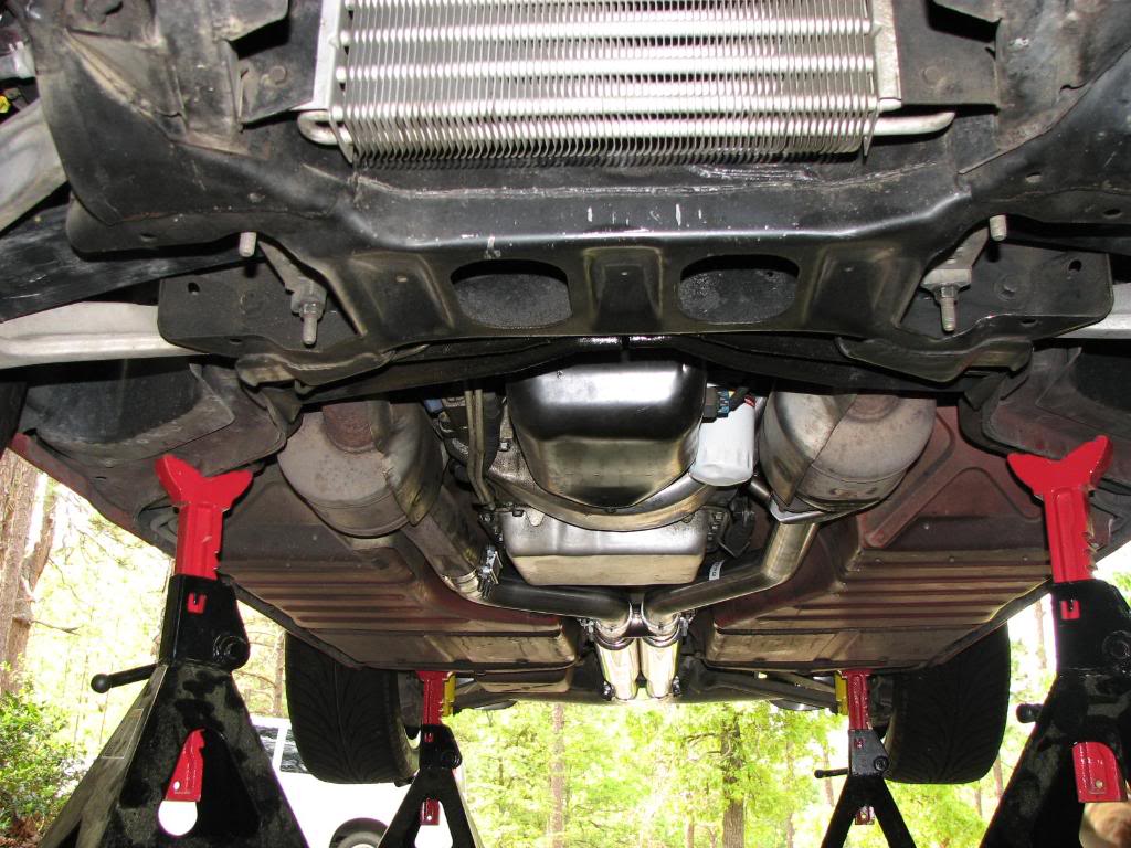
Once you get the hang of it and have those massive jack stands grumpy suggested, pulling the transmission goes pretty slick.
 
Once you get the hang of it and have those massive jack stands grumpy suggested, pulling the transmission goes pretty slick.

yeah THE (4)-to-(6) 12 ton jack stands, Ive used for decades,when properly located under the frame, to solidly support the car/truck
http://www.harborfreight.com/12-ton-steel-jack-stands-61599.html
vettejack1.jpg

are larger and heavier and taller than most guys are used too using , and yes they can be a P.I.T.A. if the floor jack you have won,t easily lift the car to the required clearance (having a floor jack that lifts to 23" is ideal ) height , but on the plus side that I feel more than compensates, you, by having noticeably increased clearance under the car/truck and much more stability.
I've seen more than one car on flimsy 3 ton rated jack stand knocked over when some moron slammed a car door , or leaned on a car while it was up on those stands , which means if you were under the car yanking on a stubborn transmission bell housing bolt you could conceivably pull the car down on top of you while your under it!
you need too read the fine print on any jack before you buy it, and having one that lifts to 23" is a big advantage, as many only reach 19"-20" fully lifted
while its not aluminum its a decent floor jack for the price especially if you get the 20% off discount ticket price.
http://www.harborfreight.com/2-ton-...vy-duty-floor-jack-with-rapid-pump-68050.html
http://www.harborfreight.com/2-ton-...vy-duty-floor-jack-with-rapid-pump-62310.html

image_12170.jpg

related
http://garage.grumpysperformance.com/index.php?threads/under-car-safety.26/

http://garage.grumpysperformance.co...se-a-hf-aluminum-floor-jack.11327/#post-57268
 
Last edited:
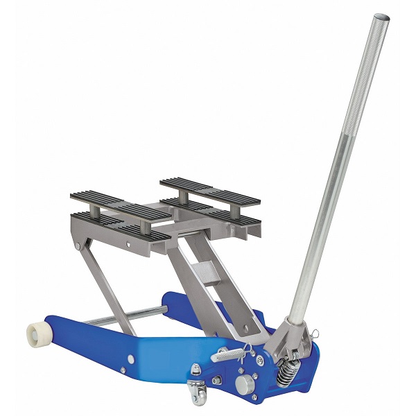
Having the car that stable is a huge plus, what i have been doing is to have the car to low to slide the transmission out from under the car due to the max height of the motorcycle jack, however i still have plenty of room under the car to get the transmission removed, lowered, and then finally i jack the front of the car up and slide the transmission out from under the car, then lower the car back down.

Also the wheels that came on the aluminium motorcycle jack have been pretty nice so far.

The front plastic wheels let the jack slide around on them pretty easily.

Long term i do expect them to have issues, however so far it's going quite well.
 
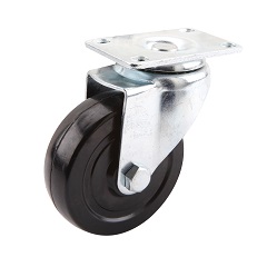
to me it sounds like you should be looking into a much better and taller set of roller castors that would both raise the height of the transmission at full height when the jacks extended and at the same time the larger diameter wheels would make rolling the jack much easier.
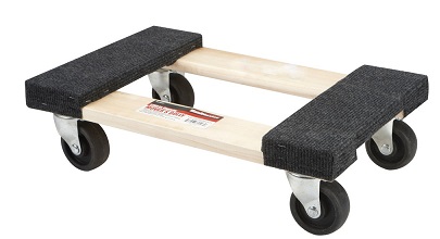
you can very easily test that out without making and permanent changes to the current motorcycle lift jack your using. simply cut two sheets of 3/4" marine water proof plywood, bolt them together with carriage bolts holding the casters , on a 30" x 18" base, so it matches the jack
Product Length 28-3/4 in.
Product Width 17-1/2 in.
and add 4 casters (don,t forget to cut holes in the doubled plywood base cart so the jack sits with its lower surface flush and cant roll off the cart,)
1500tr.jpg

framemo3.jpg

http://www.harborfreight.com/1500-lb-capacity-atv-motorcycle-lift-60636.html
21946.jpg

add 4 casters too the cart
http://www.harborfreight.com/4-in-polyurethane-heavy-duty-swivel-caster-69847.html

remember theres plenty of under the car clearance when the 12 ton jack stands are in use.
and with the casters on a cart, built like described, the jack can easily lift a load to about 6" -7" higher, so instead of a 4.5"-to-19" lift range you go to about a 11"-25" range, so with the jack stands set to the correct range its a better match
 
Last edited:
Where You at Gibbles on the 84 C4 700R4?
Check that Turbine Shaft Oil feed holes & the Front Pump stator shaft support .
The Bushings.....May have walked...Spun.
 
I pulled the pan, disassembled the valve body and detail cleaned, found the TV valve was sticking a little, fixed now.

However I think I found a cause, in the pan I found this stuck to one of my magnets.

upload_2016-6-5_18-36-6.pngupload_2016-6-5_18-36-26.png

After some thinking and poking around, I don't remember there being a hole here

upload_2016-6-5_18-37-21.png
 
The plug is a perfect fit for that hole, and that circuit is related to the 4-3 3-4

I put everything back together and ran the car on jack stands, same issue.

I do see a clear difference in pressure when in D vs OD, pressures not as high...

I'm expecting to see that plug in my pan again...

One interesting thing...

in D I take the car to like 55mph then shift it into OD, the car continues to speed up, however at a point it seems to shift down on it's own.

I also did not notice a clear 4th gear engagement, I think that sudden slowdown is the 4th gear...
 
Also I have not taken the transmission apart yet (for #3 attempt).

this weekend was spent replacing the stairs in the house, next weekend I should get more time.
 
Also the circuit with that plug, shift lever position routes fluid directly into that circuit when in OD
 
I'm expecting to see that plug in my pan again...
You cannot re-use those plugs. To help a new plug stay put, a drop of Loctite Sleeve Retainer would help, as well
as staking the VB casting at 3 or 4 places around the plug's diameter - just like the oil galleries on a SB Chevy engine.
 
Back
Top