TH400 Amateur Build

Note - a lot of my pics may not be that important as build info, but just like my 454 build, they are part of my documentation and are a great benefit if and when I need to refresh my memory or to verify what the heck I did.

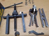
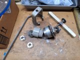
Besides a couple of different sets of bearing/bushing drivers, a lot of hand tools, measuring tools, etc. I also have some homemade tools that have worked pretty well. These include a piston retainer compressor tool, bushing remover tool, accumulator compressor and an assortment of round things on a threaded rod that are used to install (and remove) bushings from more difficult to reach units. I don't like to beat bushings into place so wherever possible I try to use some sort of threaded installer to ease them into place. Similar to a harmonic balancer installer tool concept. I also have a 20T shop press that I use for parts whenever I can, such as with the piston retainer compressor, bushings, seals etc.
1000001993.heic.jpg

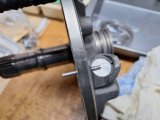
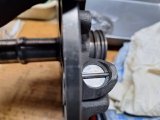
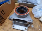
I finished up the tailshaft housing with the rear seal. The bushing and the seal were installed using my shop press. I know the red stuff on seals is intended to help avoid seepage, my preference is to add a thin smear of Permatex #2. Never have had a problem. The obvious M10 lettering is to remind me NOT to try to thread in 3/8" SAE bolts from the rear mount.
1000001995.heic.jpg

Shifter shaft seal (say that 3 times fast) installed into the case, also with a thin wipe of Permatex. All seals get a light coating of blue transmission assembly lube.
1000001999.heic.jpg


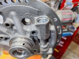
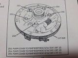
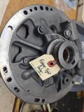
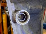
Pump tolerances have been checked, next was to give the pump body exterior side a coat of paint, just for corrosion resistance. That's the extent of the paintwork on the unit - it's buried up under the car and doesn't need a paintjob. But it is clean. Pic below is just before I gave it a light coat of primer.
1000001994.heic.jpg

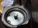
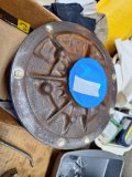
Pump bushing was replaced - I'm not sure what that dark stuff is, the bushing was clean when I installed it.
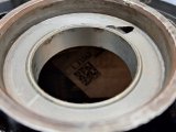
Very important! Picture below is from the front side of the pump - bushing is at same level as the bore surface. It could even be slightly proud of the surface on this side, because the gear side of the bushing MUST be below the gearset.
Front side - placement not that critical.
1000002013.heic.jpg

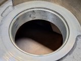
Gear side - placement is critical. Bushing must be below surface where gearsets rotate. You'll notice a few rub marks on the bushing - that's not a big deal, it's from fitting the pump body onto the converter hub to ensure there's no binding. It rotates nicely on the hub, and the marks are from the initial "set" onto the hub. There's a light coating of blue lube on the surface of installed bushings too.
1000002014.heic.jpg

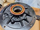
Pump body finished, seal installed. Same deal with the light smear of Permatex on the seal frame.
1000002015.heic.jpg

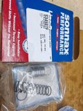
I'm waiting on some Sonnax parts for the pump pressure regulator.
After that, the pump is ready to align its two halves together - I'll use the case itself to do this.
 
Today was Sonnax pump regulator installation.
This Nick's Transmissions video was a great help to me:


1000002064.heic.jpg

These are the only original parts I re-used, according to the kit instructions.
1000002071.heic.jpg

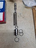
Here's the lineup of the parts to be installed. Note! the spring seat isn't in the actual installation order, it goes between the original pressure regulator valve and the spring. When installed it's at the bottom of the spring. Also, the bottom cup is needed but I didn't get it into the pic.
"Bottom" = cup end of regulator assembly. "Top" = snap ring end of regulator assembly.
1000002070.heic.jpg

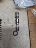
I noticed that the new Sonnax boost valve had a small dowel sticking out of the end, the instructions show a smooth surfaced valve. Looking online, this difference is ok. Picture is with o-rings installed - they go towards the outer end of the shaft. The instructions also show a separate small valve too, but in this kit it was already installed into the boost valve. All you install is the item below.
1000002073.heic.jpg

There's a pin that retains the end (bottom) cup, it just slides in and can slide right back out until you install the rest of the PR assembly. When properly seated, it's about 3/32" below the machined stator surface.
1000002066.heic.jpg
1000002067.heic.jpg

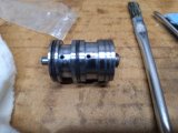
I used a clamp and a small socket going over the boost valve dowel to avoid damaging it - the clamp pressure was on the larger end of the boost valve. It all still was somewhat fiddly to do. I lubed everything with blue lube, ensured the PR valve slid easily, and carefully eased the boost valve into the bore, paying attention to avoid damage to the thin o-rings. Clamping allowed me to slowly compress and hold the assembly in place while I got the snap ring installed. I then pushed in on the boost valve a couple of times to ensure the snap ring was fully seated. It's a snug fit and takes some effort to move that boost valve with those o-rings, plus the tension of the new spring.
1000002074.heic.jpg
1000002075.jpg

Pump is now ready to join the halves - I put a reminder note to myself to not do something dumb like forget to install the gears first!

Not affiliated but wanted to mention a couple of parts sources that had reasonable prices and quick free shipping. I'll try to note parts sources as I go along, may be of interest.
Ebay seller transmaxxllc - Sonnax pump pressure regulator kit 400-LB1
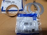
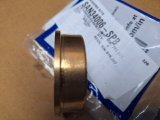
Sonnax anti-walk case bushing kit wth shims and bearing 34006-SPB
Ebay seller Feiock Performance - Pump thrust washer kit (5 selective washers)
 
Last edited:
Im learning as we go also,
I hope some of the members who have rebuilt automatic transmissions in the past will post info.
Like RICK who did a great job rebuilding his 200R4
Ive only rebuilt a few
muncie 4 speeds and about 150 PLUS engines, and dozens of clutches over the last 53 or so years
(thats one reason I started the forum, to allow info from more experienced members to flow easily,
to the less experienced members in any particular area of skill/experience/knowledge)

 
You probably already know whats in my statement below, but for others that read this thread later.

It's hard to tell from photos, but the snap ring made by a stamping process. This mean that one side of the snap ring is rounded, but the other side has a sharp edge. This sharp edge should go on the opposite side of the spring pressure. They are less likely to come out installed this way.
.
 
You probably already know whats in my statement below, but for others that read this thread later.

It's hard to tell from photos which way you have installed them. The snap ring is made by a process that leaves a sharp edge on one side. The other side is smooth and rounded. This sharp edge should go on the opposite side of the spring pressure. They are less likely to come out installed this way.
.
Absolutely right and a good reminder to note as I progress. In this case the snap ring was the same on both sides so it didn't make a difference. I should have noted this.
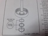
For almost every other snap ring, the bevel needs to be noted and I'll do that. I'll also note where I use spiral locks In place of snap rings.
Thanks!
 
Pump is essentially done.
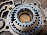
I took a lot of time to ensure the gears were in correctly, the pick points to the mark on the outer gear. The inner gear only installs one way, lugs up (into the pump). Inner gear installed the other way will destroy the pump as the gear will be driven up into the body by the converter.
1000002087.heic.jpg

One thing I got slightly hung up was a video that said if there's any chamfer on the ring gear, that chamfer goes down (towards the front of the pump). I looked at my earlier pictures of the gears and they didn't really clearly show the ring gear orientation. But the ATSG manual is very clear that a gear that is marked goes up, so that's what I did. It will give me something to worry about at night, although realistically it may not be an issue. I figure there's a reason both gears are marked.

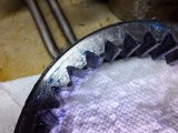
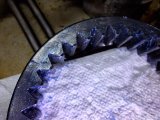
Noticeable chamfer (not on the marked side of the gear).
1000002088.jpg

Less chamfer (on the marked side of the gear).
1000002089.jpg

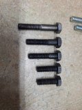
3 different sizes of pump body bolts, all torque to 18 ft/lb. I only installed them finger tight and haven't aligned the pump yet.
1000002085.heic.jpg
1000002086.heic.jpg

I put tags on stuff to remind me - the car's got tags on the suspension about tightening the bushings with full weight, filling the rear axle, etc.
1000002090.heic.jpg

Here's why I'm waiting on the pump (plenty of other stuff to do). In most of the videos I see, the pump is assembled with the gears in blue lube or tranny fluid. But in the video below, he's talking about the pump needing to be flooded with fluid to enable it to prime.
I'm not saying who's right or wrong but I don't know how I can fill the pump with fluid without that fluid running out of the pump passages.
Pump gear info starts about 11:40 in the video, includes his comment about the ring gear chamfer and filling the pump with fluid.

So at this point I've just set the pump aside until I can verify the info on the gears, pump priming, etc. What I see a lot for first start is to ensure the converter is as full as possible (critical to the pump drawing fluid), then adding 5 qts of fluid initially, starting the engine for a minute or two, then add 2-3 more qts before re-starting and easing through the gears, then final fill per dipstick.

Incidentally, I asked Nick at Nick's Transmissions (I referenced his excellent videos earlier) about that fluid he uses. Original fluid was Dex III, which isn't licensed by GM anymore. I trust his advice.
His response:
I'd use any Dex/Merc certified transmission fluid, brand is your call. I have used Castrol, Valvoline, Mobil and more in multiple transmissions without any problems. You can also use Dex VI which is full synthetic but it's usually not necessary unless your application is very heavy duty towing, hauling and/or working (i.e. snow plow trucks).
 
About the pump - from what I see, installing the pump gears with factory marks up, and simply ensuring the gears are well lubed is pretty much what the norm seems to be. Then the initial startup commences as I described above, so I think it's all ok.

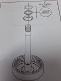
Rear Case Bushing ....

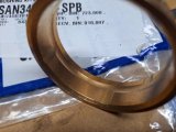
I'm using a Sonnax rear case bushing/bearing/shim kit 34006-SPB. It's the anti-walk version. That's a GM thrust bearing that's included in the kit. I've used Sonnax parts in other units, it's all quality stuff. Be careful if you order Sonnax, there is aftermarket stuff using the same pictures - you need to be sure the description actually includes the Sonnax name and part number.
1000002141.heic.jpg

The case bushing installs from the inside of the case - you can see the lip that prevents it from shifting outward. Easy install.
1000002144.heic.jpg

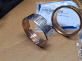
Here's the drain channeling on the Sonnax and oem style bushings.
1000002143.heic.jpg
1000002145.heic.jpg

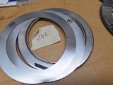
Four shims are included in the kit, two are .010", two are .015"

I took a thickness measurement of the original thrust washers = .162"
1000002147.heic.jpg

I don't know where the assembled endplay will be, but as a start I'll set up the new thrust bearing and 2 shims to give me about the same .162".
After I check it (on a dry assembly), I'll adjust the shims accordingly to get an endplay between .007" and .019", will shoot for .010" to .012".
1000002148.heic.jpg

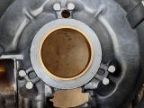
New bushing installed into case. That brass you see is the top ledge of the bushing. Note that you can't use a regular thrust bearing/shims with this bushing as the end ledge of the bushing is a larger diameter. You need to use the larger diameter bearing/shim which is why I liked getting everything as a kit.
1000002149.heic.jpg

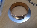
Larger diameter shims/bearing needed to go around the larger diameter Sonnax bushing ledge.
1000002146.heic.jpg

Here's that ledge of the new bushing resting on the case bore.
1000002150.heic.jpg

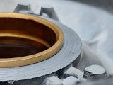
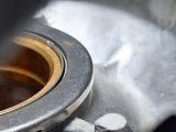
Here's the thrust bearing and shims placed around the bushing - it essentially locates and keeps them in place. The top of the bushing is below the thrust bearing, so there's no interference with the tailshaft ring gear.

1000002151.heic.jpg

I like this kit vs using an oem style bushing and driving it slightly past the inside face of the bore in order to locate/retain standard shims and a TH350 rear thrust bushing. For me the Sonnax kit is more fool proof.
 
Very slow day, amateur tedious level....

Thrust (Torrington) Bearings ....

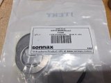
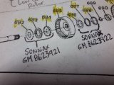
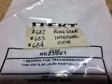
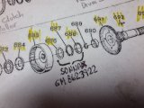
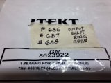
As a sort of inventory, I wanted to verify the thrust bearings included in the rebuild kit. It's a Sonnax package with 3 separate GM part number thrust bearings.
1000002167.heic.jpg

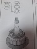
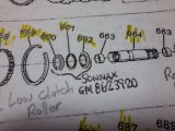
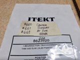
I used the references in the ATSG manual to verify what I had and where they go. The written numbers on tape that you see reference the ATSG exploded diagram numbering.

GM bearing kit 8623920:
1000002172.heic.jpg
11162023165825.jpg
1000002173.heic.jpg

GM bearing kit 8623921:
1000002174.heic.jpg
1000002175.jpg
1000002176.jpg

GM bearing kit 8623922:
1000002169.heic.jpg
1000002170.jpg
1000002171.jpg
 
Output Shaft Ring Gear Bushing .....

Here's the fun part of the day.... I wanted to replace the bushing inside the output shaft ring gear.

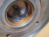
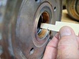
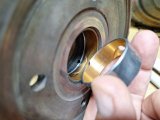
Here's what the existing bushing looked like, some wear, not terrible, but accessible.
Note the fluid supply hole.
1000002164.heic.jpg

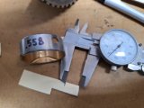
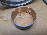
Here's what the replacement bushing looked like - it was wider than the orginal. This isn't all that uncommon on newer version bushings.
1000002184.heic.jpg
1000002165.heic.jpg

Further measuring verified that the new bushing would fit without interfering with the fluid supply hole. I didn't mind the extra width as it looks to provide more surface area bearing for the rear internal ring gear journal. It installs right to the inside ledge in the bore and has a cutout for the fluid supply hole. You'll notice that the new bushing has an extra hole in the middle. There's no corresponding hole in the bore, so I figured that it retains additional fluid and/or has more than one application.
1000002183.heic.jpg
1000002181.heic.jpg

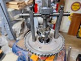
I enlisted the help of my blind pilot bearing puller. I've got a couple different sets of homemade legs so it was able to get under the lower edge of the bushing. Still took a good tug to get it out.
1000002185.heic.jpg

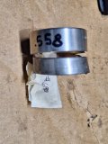
Here's the difference in the bushings. You'll have a valid question about whether or not I used the right bushing - I did check them all and this was the only one that was the needed diameter. Plus the notch at the side (to me) acknowledged the location of the fluid fill hole in the bore.
1000002187.heic.jpg

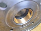
New bushing installed ok using my shop press. As you can see, the fluid hole isn't obstructed and the top of the bushing is properly located below the level of where the thrust bearing will sit. You can also see that extra hole pretty much not doing anything, maybe it helps provide a small fuild reservoir or something.
1000002211.heic.jpg

Now a bit of a problem - for me - not for a professional builder.
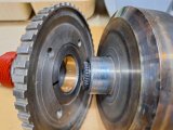
When I checked the new bushing on the inner drum gear journal, it was fine, not tight at all. You expect a new bushing to get smaller as it's installed - gets squeezed down a bit, so you may get a snug fit initially. But the new bushing ID is now too small, the journal won't fit at all, so some resizing is in order.
New bushing ID = .0398", journal OD = .042", too tight! I need to do a bit of research to see what the final fit should be. I need to be really careful on how I hone and how much I hone out the new bushing. I intend to use a brake cylinder hone with fine stones, very gently.
1000002188.heic.jpg

I did some reading on this and it seems that in many cases, the original bushings are left in place if they generally measure out ok and don't look like the surface of the moon. I'm concerned that I may embed stuff onto the surface of the bushing as I try to hone it. I will also check closely to verify that the bearing is straight in the bore, using my micrometer. This hasn't been a problem using a press, but you never know. I'm also willing to get another bushing if needed, but there's no assurance another may be different.

As always, comments and advice are welcome.
 
Welcome to my learning curve....

As I was looking at additional info/parts/supplies, I came across these:

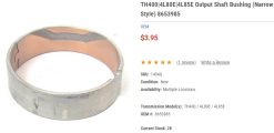
There's a narrow output shaft bushing:
1702779432714.png


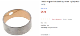
And there's a wide output shaft bushing:
1702779372012.png


It looks like I may have the wrong bushing installed, per my post above comparing the two bushings.
Along with my other stuff, I ordered two of the narrow bushings (one extra for any mistakes). I'll pull the wider bushing - no harm was done to the bore - and install a new narrow bushing that's an exact match for the original. Not sure why the kit only had the wider style, maybe they are interchangeable, but if it worked with the original narrow, it will work with the same type replacement.
I'm curious to compare the ID of the different bushings as well.
 
how about a couple links to buy the tools being used like the gear pullers?
or anything similar available commercially, so if someone follows the build they can but similar tools
like you did with the trans holder clamp

 
T-Bolt, that's very kind but remember this is a novice build. My total experience with rebuilding is three 4R70W and two TH350. All were successful, but that's not a lot of experience ;) I hope though that my plodding through this TH400 helps you out a bit.

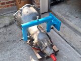
Grumpy, that's a nice stand, but I like my .25 wall tubing homemade one a lot better lol.
Regardless, a fixture is a great help, highly recommended!
20231103_120628.jpg

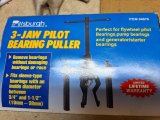
The pilot bearing puller was a cheapie HF, but I don't see it listed on their website anymore. I'm sure Amazon has a bunch of similar.
1000002253.heic.jpg

I actually have two of them, one has been modified - I made longer legs with more of a straight ledge and the bar-type fixture as well. Used as needed for the circumstance. If you compare them with the stock (slightly bent) leg at the bottom, you can see the difference in the leg hook.
1000002254.heic.jpg

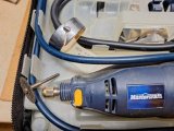
I also sometimes use a Dremel tool with a cutoff wheel to cut a slot in the bushings, as I did today removing that new wider bushing.
The trick is to cut the slot almost, but not quite through the bushing. This lets you ease a small screwdriver behind the weakened bushing without damage to the bore. The bushing easily breaks away.
1000002255.heic.jpg
 
It is much better to watch a "novice" rebuild, professionals rush through and have tools and experience an average person dont have, and they often skip to mention small but important details, almost(?) as a trade secret...
Where to buy parts, and like cutting the bushing was a great tip, for me at least. I almost look forward to rebuilding my TH400 now :like:
Your comments are well appreciated and along with Grumpy and Rick give me continued motivation!
 
Back
Top