TH400 Amateur Build

Before I add more progress I wanted to note some of my project organization methodology - I'm sure Rick is way ahead on this - but regardless, anything you do to keep track of things, specs, measurements, pictures, etc, yields much better end results.

All my car projects and "sub-projects" like the 454 and this transmission get a bag and tag at disassembly, along with pictures and notes pertaining to that part of disassembly.
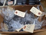
1000002264.heic.jpg

I also keep a binder on any project I do. I think it's especially important for specs and measurements, like on my engine build. But I also use it for parts listing, receipts, general info, etc. - and I use it all the time. Example is that I will list what parts are being ordered, from where/cost, then I'll check them off as they arrive and put the receipt into the binder.

I also keep a general work log as I go. Example for today: "coolant fill, change PCV valve, work on transmission". Nothing complicated but it's a good progress chart (I'm on page 13 of this entire car build lol).
1000002265.heic.jpg

Grumpy always talks about HAVING A GAME PLAN! So true, and I do this initially so I can figure out where I'm heading, IMO especialy important on long-term complicated projects. But basically there's nothing that special about what I'm doing, it just really helps my old brain to clarify, document, and remember things.
 
Bronze Thrust Washers .....
Center Support Bushing .....


Ok, so today I continued to move generally from the back of the unit to the front, as parts allow. You may see that I jump around a bit, depending on what I'm able to do at the time.

I took a look at the thrust washers in the kit - they are all steel/bronze vs the original plastic washers. I think a much more robust design.
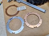
Below are 2 of the new steel/bronze washers (one's just flipped over) next to the original plastic washer. You will see that I mic the thickness of all removed and new materials as a check. In this case they were the same - the plastic is an average of 4 measurements around the washer. It had some wear. The two new washers are the same dimensions and thickness.
1000002266.heic.jpg

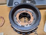
One of them installs here, on the internal ring gear.
1000002267.heic.jpg

Bear in mind, this is all a preliminary initial assembly, just like an engine. Everything here will be assembled dry to check clearances/specs, then final assembly will be wet, with clutches soaked, assembly lube applied etc.

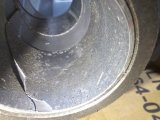
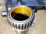
I next inspected the bushing at the center support. I had some concern about the final fit - would it need honing?
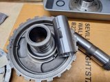
The sun shaft (right side) has to fit into this bushing. It has a very specific depth and orientation requirement.
1000002268.heic.jpg

The original bushing didn't look that great so I decided to replace it. I did mic the original and new bushing ID's and the shaft OD just to get an idea of what the compressed vs open bushing dimensions were. I also slid the new bushing onto the shaft - it had a bit of play which is good considering it will be compressed slightly from the interference fit. But so did the output shaft bushing yesterday and it ended up being too tight.
1000002269.jpg
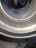
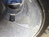
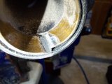
That's a bit of an illusion below - the surface isn't peeling, it's a portion of the bushing surface that's smeared over the slighly recessed fluid channel.
1000002270.jpg

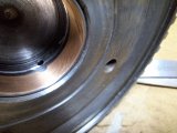
Note the specific orientation of the bushing window to access the fluid hole. You can also see that the surface has wear.
The sun gear shaft itself looked fine, no scarring and consistent measurement, just needed a bit of Scotchbrite on the surface.
1000002271.jpg

Original bearing installs just below flush on one end of the center support.
1000002272.jpg

I again used my trusty 20T press to ease the new bearing into place. As always, it's important to start the new bushing straight.
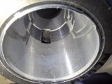
Orientation was per the original, you can see the fluid hole access. After installation I also cleaned up the surface slightly with Scotchbrite and gave it a thin wipe of blue lube.
1000002273.jpg

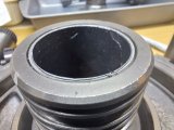
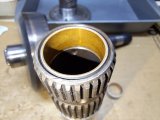
New bushing also installed just below flush. You can't really see, but the new bushing has those recessed fluid channels on opposite sides, the original just had the channel on one side. Seems like a fluid transfer improvement to me.
1000002274.jpg

Moment of truth and I was happy - the sun shaft has a very nice fit, moves freely with no binding.1000002275.heic.jpg

Next I want to look at the intermediate clutch setup - I want to do a dual feed and go with a 34 element sprag at the direct drum, and I'll be adding spiral locks and thicker snap ring(s), etc. so I need to order some parts. I will be using a 4L80E direct drum. But as mentioned, I'll work on something else in the meantime.
 
Picture count is 197 and counting lol.

Slight side-road here, just to talk about clutch pistons. There's much more info out there on molded, aluminum, steel, etc but for my purposes I'm just noting the least-preferred piston.

Below are the intermediate (L) and forward (R) clutch pistons. I think that in my transmission, the direct clutch piston looks like the forward clutch piston.
The piston on the right is least preferred as the bearing area on the clutches is just that thin wavy spacer. The piston on the left is better (not best but ok) as it allows a much more solid and larger bearing area.
1000002308.heic.jpg

Not sure if this explains better but the plastic represents the clutch pack - you can see that there's a solid ledge below it.
1000002309.heic.jpg

Now look at the very thin bearing area of this piston - it's just the edge of the wave spacer. I know it works but for my application I'll be changing to a steel piston similar to the intermediate clutch. Depending on cost I may look at aluminum but in my case the steel should be fine.
1000002310.heic.jpg


Not an expert explanation of all piston factors, but this one is worth noting I think.

I've also gone through all the old and new steels and measured their thickness. I may need to change some, get some additional thicknesses, etc depending on what the clutch pack clearance number is. As I mentioned, the initial assembly is with dry components and without sealing rings in order to make it cleaner and easier to get the clutch pack clearances and rear, front plays to spec.
1000002290.heic.jpg

In the case of original clutch packs, I've measured thickness of each steel as well as the overall thickness of the pack just for a general reference.
Almost all of the steels were in decent shape, so if I'll use them as needed to get proper clearance on the new clutch packs.
1000002291.heic.jpg


I've also gone through and identified new thrust washers against the original ones and added the ATSG manual number.
You've seen videos where pro builders can just put everything into one container, but I can't do that, so I catalog everything. I'll use this as a checklist of sorts against the ATSG exploded diagram to be sure I've accounted for everything.
1000002292.heic.jpg
 
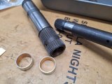
Sun Gear Shaft Bushings .....

Sun gear shaft is on the left, main shaft is on the right. I do go over all journals lightly with 2000 emory/oil and a bit of scotchbrite just to give them a light cleanup.
1000002296.heic.jpg

One bushing in each end, this is where the main shaft rides. The bushings are the same for each end.
One end was a bit worn, as always I use the pictures to remember depth of installation.
1000002294.jpg

The other end was a bit better, but I replaced them both.
1000002293.jpg

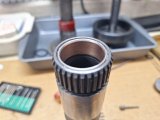
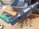
Here's an original bushing weakened but not cut through with the dremel, just a few light taps started breaking it away with no bore damage.
Of course a thorough cleaning/air gun/repeat is done to ensure all of the debris is gone.
1000002297.jpg

I've gotten into a little pattern of bushing "pre-check" - won't tell me that final "feel" of the new installed bushing, but it's helpful to get a ballpark idea of what I'm working with. Mainly if things are way off, then honing may be anticipated.
In this case, the old bushing ID's as installed were 1.00". The main shaft journals measured out at .998", so .002" clearance. A bit too much clearance - you could feel some play - plus debris in the bushings, so they got replaced.
The new un-installed bushing ID's were 1.003". Installed, they compressed to .9985" so clearance of .00185".
EDIT - I left the numbers above in place but the final clearance calculation isn't right. As was pointed out in the following post:
.9985 - .998 = .0005 NOT .00185!
Good reason to appreciate an extra set of eyes and input!


My understanding is that some sun gear shaft bushings are a hone-in-place bushing with target clearance of .0015". For my purposes, I'm fine with the current clearance, it's actually a noticeable improvement from the original bushings - the main shaft goes in fine and turns freely with just a very light touch of blue lube. It's even better with a bit of tranmission fluid.
Probably an overkill paragraph, I just like to understand the details of what I'm doing.

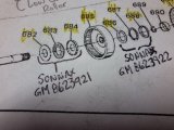
New bushings installed.
1000002321.heic.jpg

Nice easy fit with the main shaft.
1000002322.heic.jpg
 
Last edited:
Are you sure about that clearance of .00185 ???

.9985" - .998" = .0005"

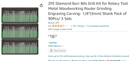
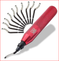
Are those deburring tips? Have not seen a selection like that. Do you have a part number?

View attachment 18497
.
LOL! man I'm dense on math - you're correct Rick. :facepalm: How embarrasing!
At any rate the shaft fits fine and that's the last of my calculations that I'll post lol.
As always I appreciate your looking/asking though - you saved me a couple of times on my engine build.

The bits are like these:
1703120551063.png

I also have carbide type with 1/8 shanks, the ones above I think may work better with softer materials, but they seem to do fine to grind a slot into bushings. Obviously they aren't industrial level, but for the price they work pretty well.
 
LOL! man I'm dense on math - you're correct Rick. :facepalm: How embarrasing!
At any rate the shaft fits fine and that's the last of my calculations that I'll post lol.
Funny, no telling now many times I've done the same thing!!! ;) It's always good to have another pair of eyes, that goes for everyone.

Thanks for the info, I thought they were a deburring tool.

1703106900193.png
 
making minor mistakes is how ALL of us learn,
(part of paying your dues and gaining experience)
keep posting the the whole threads informative and impressive!
 
Shift Linkage .....

Small stuff today, we're going to do a bit of holiday travel, so no posts for week or so. I've also got to order a number of parts needed to get into "serious" re-assembly.

Installed the manual shift linkage today and did some reading/viewing on assembly again, too.

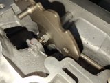
New manual shaft seal, the rest of it was simply re-installation of cleaned parts. This shows the installed shifter pawl, note the retaining nail (that's actually what ATSG calls it) that retains the manual shaft. Doesn't really show well but there's a slight bend in the new nail to keep it in place. What was surprising was that there was a cotter pin in there. I installed a B&M shift kit about 20 years ago, maybe I removed the pawl/shaft for a new seal or something and used a cotter pin. Don't remember!
The projection on the shifter pawl (top left) is what engages the manual valve in the valve body - that's the RND21 gear selection on the shifter.
1000002344.heic.jpg

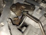
Other end of the linkage rod that engages the parking pawl. Bolts torqued to spec, everything works nicely.
The larger diameter part and spring on the linkage rod pushes rearward (towards the left in the pic) against the parking pawl lever and moves the lever into the geartrain lugs, stopping the geartrain from turning. That's when you select "Park" position on the shifter. Any other movement of the shifter pulls the linkage rod forward and releases the parking pawl, allowing the geartrain to turn.
1000002343.heic.jpg


Merry Christmas to you and your families and my thanks for the continued support and advice!
 
Output Shaft Ring Gear Bushing Part 2 .....

Well, I had a bit of unexpected free time today so I wrapped up the output shaft ring gear bushing. That was the one that was replaced with a wider style bushing and was too tight on the output shaft journal. I received two replacement original-style narrow bushings, same as what I originally removed. There is one difference though, the new one has a small notch - the only place that I figure it installs is with notch towards the fluid feed hole in the output shaft internal ring gear bore.
Again, I tag everything per the ATSG diagram, just so I can ensure I've got things in the right place.
1000002349.heic.jpg

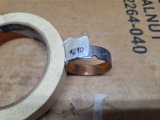
Here's that bushing in sequence, #690 to the right. As it's actually installed, it gets a pink color highlighter so I verify what I've done, just like I do with the ATSG assembly steps. Overkill for those that work on this units, but necessary for me. I developed this methodology after pulling my first 4R70W transmission rebuild 3 times (!) until I found that I missed installation of intermediate clutch piston outer seal. A true learning experience!
1000002175.jpg

Always note to set bushings in squarely - this shows the new bushing as a no-go on the output ring gear journal. Even with the ID not compressed from being installed, if you look closely, it just takes a bit of crooked to be a problem. So, I take great care to start the bushing in square and monitor it as I slowly press it into place.
1000002351.jpg

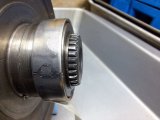
Installed into place before I finished out the surface. Note the orientation of the bushing notch towards the fluid feed hole, as well as the installation depth of the bushing - important since a Torrington bearing assembly rides in that recess around the bore.
1000002354.jpg

Yes, this one was a tight fit as well. I can't keep changing out bushings, so I used a fine stone small bore hone (oiled) to carefully open up the bushing ID. It's not an oilite type bushing so I didn't see an issue with honing it like this. So, after a small series of steps - hone, check, repeat - I got a snug fit. I then finished the surface with Scotchbrite.
1000002352.heic.jpg

Fitup feels fine, it's snug but not binding. You can see a bit of rub on the right side but I think that will be ok, and that after some rotation that will clearance out.
1000002356.heic.jpg
Here's how the output shaft and rear ring gear drum fit together. I used a couple of washers as substitute spacers for the torrington bearing that fits between them - You can see a bit of clearance between them.
1000002357.heic.jpg

Another note on my assembly process - I use a combination of the ATSG manual and online information, including videos, to help guide me through the steps. Example - as I installed the simple task of the manual shift lever assembly, I still used the ATSG manual as my pink-marker-done checklist. Just my methodology for what it's worth. As I get into more complex assembly, I look at a lot of online info to get familiar with what I'm doing. I want info on each task swimming in my brain.
1000002355.heic.jpg

OK, that's REALLY it till January ;)
 
I've got some more parts ordered, but I'm not going to assemble the transmission until I have the car ready to control the transmission (run/stop/shift), plus making cooler lines. The cooler lines will be a combination of 3/8 tubing with -6AN hoses/fittings at each end.

My reasoning is that as the unit is assembled, the clutches will be first soaked in transmission fluid. I keep them in fluid for several days before installing. My concern is that if I get the transmission done, then do the drive stuff, fluid will slowly migrate out of the clutches. Of course they won't be dry at first start but I'd rather be able to get the unit installed and running within a few days timeframe with the clutches as soaked as possible. Maybe overkill, but I don't know timeframe to do the other things needed to drive.

Currently ordered (as I assemble I'll post pics):
- used 4L80e direct drum assembly (drum, piston, springs, retainer, 34 element sprag). In good shape and all GM parts.
- aluminum forward clutch piston
- spiral locks for forward, direct, and intermediate springs retainers
- Sonnax case saver at center support
- Sonnax heavy duty spring retainers (2) for forward and direct clutch
- Six additional intermediate clutch return springs
- new single terminal downshift case connector
- New dipstick/tube
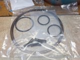
Edit - I also decided to get a set of Teflon sealing rings. Wasn't a big cost. The rebuild kit includes cast iron rings, but after some research I thought I'd try to use the Teflon seals, assuming the line pressure may be slightly higher from new pump regulator. The Teflon seals for pump/center support are scarf cut, all others are solid and will require sizing. I'll post more as I get to each subassembly.

I did get a spiral lock retainer to replace the intermediate clutch snap ring, but I'll need to verify clutch clearances everywhere of course.

I'm also researching valve body upgrades related to the various valves, more later on this.

So, main progress is reverting to the car itself, but I'll still be dry-assembling the transmission as well.
 
Last edited:
Reaction Carrier ......

Couple of odds and ends, filling in some work here between chasing a couple of brake line leaks.

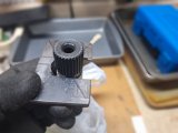
This is a little "tool" I made when I'm ready to install the rear geartrain. The assembly is fairly heavy and difficult to hang on to with just the end of the main shaft available. There's a fancier tool available, some folks use a welding plier type clamp or visegrips.

I saw this used on a Nick's Garage video and thought it was simple and effective, just a piece of plate slotted to fit into the shaft recess below the end splines. Much easier to hold the geartrain while lowering it into the case.
1000002403.jpg
1000002404.jpg


New bushing installation into the reaction carrier (I think I've seen it called the reverse drum too).
This bushing sits just below flush on the center support end of the reaction carrier bore. That's some blue lube on it.
1000002548.heic.jpg

It doesn't go all the way to the bottom of the bore.
1000002549.heic.jpg

Center support fits into this bushing, there's a thrust washer that goes in between, but I'm not ready to assemble anything yet. Also, the low roller clutch isn't in place either.
1000002550.heic.jpg

This drum has the reverse band riding on it and will need a bit of surface cleanup before going further with the rear geartrain. I have a new th400 grooved reverse band because I'm re-using the original reaction drum (shown above). If I went with a smooth band, I'd have to buy a 4L80E reaction carrier because the drum I have will tear up a smooth lined band. Here's an excerpt from a Sonnax article about 4L80E no-reverse that helps explain early/late bands and drums and is applicable to the th400 too.

1704754427736.png

More info to come on drum cleanup and of course further assembly.
 

Attachments

  • 1704753991147.png
    1704753991147.png
    217.7 KB · Views: 0
Reaction Carrier Surface Clean-up ....

I started out yesterday bleeding the brake system - it's a total disaster with leaks at almost every fitting. I'll cover that in the other thread.

So I walked away for now and decided to do some more transmission work. Every little bit helps move this along.

I needed to address the surface of the reaction carrier - I think this is also referred to as the reverse drum? This is what the reverse band clamps onto, not just for reverse. There's significant speed on this carrier so I thought some attention was needed.

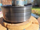
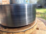
Here's what the surface looked like. You can see mild surface marks from the reverse band. There were a couple of lines that you could feel with a fingernail, but nothing terrible.
1000002638.heic.jpg

I mentioned in the post above about using the right carrier with the right reverse band. The newer 4L80e version is smoother, and the oem style th400 is esssentially 3 bands together of a rougher material. I think that the newer style may be more durable in the long run, but I'm not worried about 100k mile durability.

You can use the newer band on the newer 4L80e carrier, but you can't use the oem th400 carrier with the newer band, it will degrade the band quickly. The carriers have different surface finishes. I have a new oem reverse band in the rebuild kit, and since the reaction carrier wasn't terrible, I decided to give it a mild surface clean-up, similar to cleaning up a brake rotor before installing new pads.

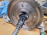
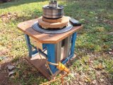
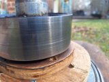
I don't have a lathe, but I do have a home-built "brake rotor spinner" that uses a 1/2hp motor attached to some round wooden rotor supports. there's bolt holes in the wooden supports for a rotor. I attach the rotor to the support and use different grades of sandpaper to just give the surface a cleanup. Nobody seems to turn rotors anymore. It's not a lathe-turned finish but it gets the job done vs doing nothing to the rotor surface. In the picture below, the spinner is set up for the reaction carrier - that's a rod with a clamp to keep the drum in place.
1000002639.heic.jpg

I used some WD40 as lubricant and did some spins using 400, 600, and 1000 grit wet/dry sandpaper. The goal was not to make a lathe-turned completely cleaned surface, just to take off the surface debris from the old reverse band. I wasn't worried about the couple of deeper grooves.
For a backyard process, I was happy with the end results.

After 400 grit:
1000002641.heic.jpg

After 600 grit:
1000002640.heic.jpg

After 1000 grit:
1000002645.heic.jpg

Based on what I've found online about re-using these carriers, this should now be fine for installation. You can sometimes find refurbished th400 carriers online, but I know the condition of the planetaries in this one - they are in great shape. I don't know what I'd be getting other than a carrier that's maybe been turned on a lathe.

Waiting on a bunch of parts - listed in a previous post above - then I can move into dry assembly to check clearances.

And fix my #*$# brakes!
 
It looks like your doing a fine job! CONGRATS, but NEVER ASSUME!
do the required research, ask questions and get related info from at least three sources,
don't skimp on parts or ignore any thing you suspect is worn, or might be damaged,
doing it correctly is always cheaper and faster than having to pull it down a second time.
to replace parts that failed, or were improperly installed,
that you thought were (probably ok)
never skip over some part install info or part inspection or assume!
ask questions even if you think you know the answers ...
be damn sure you KNOW, don't GUESS!
yeah we all make mistakes... :facepalm::swearing:
I've sure made more than a few!
it's called paying your dues and gaining experience!

try to learn from
OTHER PEOPLE'S MISTAKES

IT A WHOLE LOT CHEAPER!!

BTW LOVE THE POSTED PICTURES AND RELATED INFO! :like:
 
Agree with you. At the same time I'm cleaning up the surface on this th400 reaction carrier, I'm also still considering using a 4L80e carrier with the applicable 4L80e reverse band. Many times I start in a direction but not always end up staying with it. I post this as somebody else may be in the same boat and be thinking about best choices. In this case, it's not about a high hp build, it's about what will work dependably.
 
Forward Clutch Pistons .....

Not much going on, I've got a lot of transmission and brake parts ordered, but they are in the black hole of USPS shipping. So they are just trickling in.

I'm not affiliated with any Ebay seller, but I will mention them when they have good products at a reasonable cost.
Luv2rev64 - th400 front clutch piston

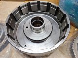
Here's a comparison of the original forward clutch piston (left) and the used aluminum forward clutch piston I bought (right).
0162024161135.jpg

As you can see, the "newer" piston has a better bearing area for the clutches and a different clutch spring retention.
Also noted is this is a no-checkball piston to match the original piston. The drum has the checkball - if you replace this piston, look to see if the original has a checkball or not.
 
Last edited:
Assorted Spiral Lock Snap Rings ....
4L80e Direct Drum Assembly ....


More parts arrived today, I'm pleased with the Ebay sellers I bought from, so here's a mention.

Feiock Performance - Forward/Direct clutch spring retainer spiral lock (2 locks), Intermediate clutch return springs (6), Intermediate clutch & sprag spiral lock kit (2 locks)
EFTP Hard Parts - 4L80e - Direct Drum w/34 element sprag, 1991-ON (used), complete drum assembly - everything except clutches/steels. I won't be re-using the original th400 direct drum assembly with the stock sprag.

Here's the spiral locks and return springs. I'm using spiral locks wherever possible.
1000002729.heic.jpg

The 4L80e parts look like they came from a low mileage unit, very happy with them. Because of their good condition, it's not necessary to buy a 34 element sprag or molded piston, nor try to piecemeal this assembly. These are all GM parts, so there's a decent level of quality vs aftermarket. if I had to buy a new sprag, I would get the Borg Warner 06763AM sprag. My understanding is that BW makes the sprags for GM and other mfgs.

This drum assembly was packaged well, the seller was smart enough to put the sprag and small parts inside the drum where they were protected during USPS contorted shipping. Smaller parts were also separately bagged inside the padded box.
1000002721.heic.jpg

Drum looks almost new, I couldn't even find wear marks from the steels.
1000002720.heic.jpg

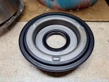
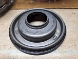
The molded piston is in very nice condition - there's some minor marks on it from the spring retainer assembly but nothing abnormal.
1000002723.heic.jpg
1000002722.heic.jpg

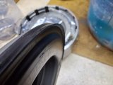
The edge seals are in great shape, not brittle or overheated, and the edges aren't worn from a million miles of use.
1000002724.jpg

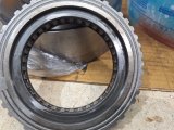
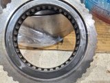
The 34 element sprag is also in very good condition.
Minor wear marks on the races, not a big deal.
1000002725.heic.jpg
1000002726.heic.jpg

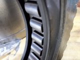
The rollers themselves look excellent.
1000002727.jpg

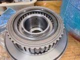
And the overall fit of the sprag onto the drum is very snug, as it should be. A new sprag has to be sort of worked onto the drum, not a loose fit. This sprag has a very good fit, needed also to be worked onto the drum, and works perfectly. In the picture below, I had just started to work the sprag onto the drum, it definitely didn't just flop into place.
1000002728.heic.jpg
 
Last edited:
Im glad to see (SCAMBAY :swearing: ) is not screwing you yet! :like:
 
Back
Top