TH400 Amateur Build

Rear Gearset ....

I'm now starting to get into the pre-assembly to check clearances.

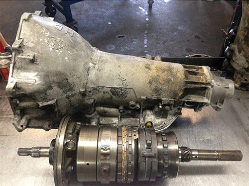
First up will be the rear gearset.

This is a great instructional video from Nick's Transmissions

Starting off really simple! I need to have a base to assemble the gearset - I'm using a cleaned out pool chemical bucket.
It's got a reinforced top that should hold the weight of the assembly.
1000002713.heic.jpg

1000002714.heic.jpg

1000002718.heic.jpg

There's three Torrington bearing assemblies that I'll be using (all part of a Sonnax bearing kit). They are all slightly different, and I'm taking great pains to not mix them up. But, as a "just in case" I've done way overkill by engraving the ATSG part number on the races of each assembly. It's extremely light, won't mess up anything. I'm probably the only guy in the world that would do this.
1000002717.jpg
 
Last edited:
You should do a separate write up about this device ..... most interesting ????

Contraptions.JPG


But, as a "just in case" I've done way overkill by engraving the ATSG part number on the races of each assembly. It's extremely light, won't mess up anything. I'm probably the only guy in the world that would do this.
I don't know about the ONLY ONE, I sure wish I had thought this on my trans !!!

That's an excellent idea and I have an engraving tool ......damn !!!

Incredible attention to detail ....loving it !!!
.
 
It's kind of rigged up lol, but it works. Its a steel frame with unistrut to mount the 1/2 hp motor and I just have an on/off switch. Someday I'll probably add a speed controller, I have to be careful of the 3450 rpm. I installed a standard pulley on the shaft and drilled it for four bolts to attach the round wood base. Bolts going thru the base attached a brake rotor. It was all on the sketchy side but the results were good - not like a lathe turned rotor, but pretty nicely cleaned up. Never any issues with brakes. I keep telling myself one day I'll make a better version but its been fine for the infrequent use it gets.

I've long used an inexpensive engraver to mark parts, especially those that needed cleaning where tape or a tag would not last. In a lot of cases it's come in handy to add unobtrusive reference or alignment marks where things had to go back together in a certain way. It's a handy little tool.
 
Ive always liked to see, guys build custom tools that show ingenuity/originality and some thought!
 
In addition to the Nick's Transmission rear gearset video above, this video from Southpaw is also of great help. Both videos will be used along with the ATSG manual, can't be too careful.


Also, a good article from Sonnax related to four clearance measurements on the th400.

 
Rear Gearset .....

I started on the rear gearset pre-assembly today. The intent is to install it generally "dry" in order to check the clearances as indicated in the ATSG, in the transmission video, and the Sonnax article I linked above.

Besides the blue assembly lube, it's convenient to use a little vial with transmission fluid mixed with a tiny bit of assembly lube for getting some fluid onto bushing surfaces and into bearing surfaces.
1000002836.heic.jpg

The original rear thrust bushing/shim combo measured out to a total thickness of .162. I'm replacing these with the Sonnax 34006-SPB anti-walk bushing kit that's supplied with a Torrington bearing and two .010 shims, two .015 shims. The Torrington bearing thickness is .141, so I added a .010 and a .015 shim to give a total thickness of .166 as a starting point. I'll adjust the shims as needed to get correct endplay.
1000002813.jpg

The info I find indicates that the rear endplay is usually a bit loose. ATSG shows rear endplay as .007 to .019. My target endplay is .010, so this pre-assembly is just to see what I need on the rear output bearing shims.

I did engrave the shims so if the marker wears off I can easily see what I've got.
1000002812.heic.jpg

Shims go in first (against the case) followed by the Torrington. It's all nicely centered by the lip on the anti-walk bushing.
1000002815.heic.jpg
1000002816.heic.jpg

Next was to install the low roller clutch into the reaction drum. That's the drum that I cleaned up the surface on. I could have probably re-used the original, but a new clutch isn't expensive and has zero rotation cycles, so it seemed like a good idea.

I'm ok with hecho en mexico, vs hecho in china.
1000002818.jpg

The clutch had a very nice snug fit into the drum, and the indentions in the drum itself are still well-defined. As outlined in videos, it needed to be slightly worked into place. After this pic, I added some transmission fluid as lube. All the rollers also got a smear of blue lube when I placed them back into the cage. The open top side of the cage goes up.
1000002821.heic.jpg

Test fit of the center carrier into the reaction drum, which had also received a new bushing. This is a good reason to check all bushing fits, so you don't wrestle with this stuff when assembling. The fit of the carrier and its rotation felt very good - it's a feel thing if you've done any sort of bearing or bushing assembly before.
1000002822.heic.jpg

Very smooth rotation counter-clockwise, locks when turned clockwise as it should.
1000002823.heic.jpg
 
Rear Gearset .....

Had a bit too many pics for one post, so I'll split the info.

These are the three bearing assemblies in the th400, these are all new replacements in the Sonnax package that came with the rebuild kit. If you recall, I marked them with the ATSG diagram numbers. I'm using two of the assmblies today.

This is the 3921 assembly that installs into the interior face of the rear internal ring gear.
1000002824.heic.jpg

Sequence is clearly shown in the ATSG manual and in Nick's rebuild video. Installs from right to left as bottom to top.
1000002825.jpg

The 3922 assembly installs on the outer face of the rear internal ring gear.
1000002829.heic.jpg
Note - in the picture above, the top race of the bearing (on the left) is shown upside down. It caps over the bearing when installing - should be obvious, but I've missed the obvious before.
 
Last edited:
Rear Gearset ....

Rear gearset assembly continued with placing the selective thrust washer into the rear output carrier, which I think is also called the rear planetary, if I've got that understood right. This is a bronze-faced steel washer vs the oem plastic washer. This can also be changed out if the carrier to reaction drum clearance isn't right, see Sonnax article/Nick's transmissions. I believe that this clearance isn't always checked, which may be a reason why there's only this thickness in the rebuild kit. It's engraved on the backside. Note! I realized as I got to the end of this bit of assembly that I really didn't need to put this washer into place at this stage.
1000002830.heic.jpg

Here's where my expensive gearset holder starts to come in handy.
The output carrier is placed upside down, and the rear internal ring gear is placed through it. This is done gently, as there's the 3921 Torrington bearing that's being held upside down by blue assembly lube. That ring gear has to mesh with the four planetaries in order to fully seat. It looks like the interior face of the rear ring gear is just going to grind against those rivets, but the final assembly keeps the ring gear away from them - the sun gear rides on the 3922 bearing.
1000002832.heic.jpg

1000002833.heic.jpg

The assembly is then flipped over and the output shaft (that's gotten a new bushing) with shaft attached is installed on top of the internal ring gear. It will ride against that 3922 Torrington.
Note the four holes in the output gearset - those were for the oem 4-tab thrust washer, which has been replaced by the Sonnax output bushing and Torrington bearing.
0232024193144.jpg

The snap ring to retain this part of the assembly is set into place. It has no bevel so it can be installed either way. Always be sure to verify that any snap ring is fully seated. Again, rotation is checked to see that everything is playing well together. So far, I'm happy with the way everything fits together and operates.
1000002834.jpg

This thing's starting to get some weight on it, and it still has more parts to add before setting it into the case.
1000002835.heic.jpg
 
Last edited:
I really like the detail, pictures and related info, as it might help others! :like:
 
Rear Gearset .....

More gearset assembly.
And another mention that I used the two above referenced videos and ATSG as a guide.

I had mentioned it before, here's the new steel/bronze thrust washer at the rear output carrier compared with the original plastic washer. You can see that the new washer is more robust and wider than the original washer.
1000002890.heic.jpg

Sun gear gets installed onto the sun gear shaft.
Beveled spine edges install down.
1000002893.heic.jpg

Straight spline edges install up.
1000002891.heic.jpg


Sun gear fluid hole has to line up with the fluid hole in the shaft.
1000002894.heic.jpg

I shone a light into the shaft after the sun gear was installed onto the shaft, just to highlight the two holes lining up.
1000002895.jpg

Sun assembly inserted into the rear output carrier - it helps to slowly rotate the sun gear to mesh with the four planetary gears inside the carrier.
And care was taken to keep the sun gear shaft and gear from separating at installation, ensuring fluid holes are aligned.
1000002897.heic.jpg
This is also another reminder to pre-check all new bushings - in this case I had checked the new bushings in the carrier and the sun gear shaft so that I knew they would all fit well before this stage of assembly.

As you can see in the picture above, the silencer ring was installed onto the carrier too.
1000002898.heic.jpg

There's an attachment limit to each post, so I'll continue gearset on the next post.
But here's a bit of case prep with a couple of pictures.

Sonnax bushing and output bearing/shim assembly installed into the case. I may need to change shims depending on the endplay reading.
This also shows the fretting ring installed into the case, ring opening at the 9:00 position.
1000002887.heic.jpg

I'm 99% sure this is where the fretting ring goes in the case. It's not in every transmission - if the center support lug thickness is .327, a fretting ring is required. If the lug thickness is .362, a fretting ring is not required. So it seems that it's there to take up the difference in lug thickness. In my case, I know it's required because it was in there to begin with (I measured the lug anyway).
The groove just above the fretting ring location is for the center support snap ring.
1000002889.jpg
 
Rear Gearset ....

The reaction carrier (I think it may also be called the reverse drum) was placed into the rear output carrier.
Slight turning when installing helps get it seated down all the way. It's bearing on the #674 washer mentioned above.
1000002900.heic.jpg

It looks like this when fully seated.
1000002899.heic.jpg

The 3920 Torrington assembly was installed into the center of the reaction carrier - it sits on top of the sun gear.
The bearing pieces are installed right to left as bottom to top.
1000002902.heic.jpg

Down into its new home on top of the sun gear. Note the new bushing in the reaction carrier too.
1000002903.heic.jpg

The center support was then installed into the reaction carrier, using a counter-clockwise rotation while gently working it into place.
however, before doing this, a new bronze faced washer #656 was inserted into the carrier side of the support. This replaced the original plastic washer.
1000002936.jpg

Center support installed using counterclockwise turns to work it into place.
1000002904.heic.jpg

Its looks like this when fully seated. Feels very good, nice cc turn and locks the drum when turned clockwise.
1000002905.heic.jpg

I used the info in Nick's Transmission video and the Sonnax tech link to try to measure the lower planetary to reaction drum clearance. In Nick's Transmission video, he called it low planet to high planet clearance.

Not an exact science, a lot of it is by feel. I know its crooked in the picture below, just to give an idea. As you hold the center support on either side, pull up on the reaction drum, ideal travel (clearance) should be .007 to .015.
1000002907.heic.jpg

With a second set of hands to help, I used a feeler gauge to see what the clearance to the lug was before and after I pulled up on the reaction carrier (reverse drum). I came up with .010, which is fine.
1000002908.heic.jpg

At this point the assembly was ready to drop into the case for endplay check, which is why you don't see any sealing rings installed yet onto the center support. Always checking, shafts and drums all turn nicely, no binding or looseness.

I did add a bit of blue lube onto the center support lugs and inside the case to help the assembly slide into place. In my case, I had to really work the gearset assembly loose from the case at disassembly, so I was anticipating a tighter fit at assembly.
1000002912.heic.jpg

I ran into some difficulty with the assembly insertion, seemed that it would not seat fully in order to get the center support snap ring installed.
Looking into the center support bolt hole at the valve body, the gearset needed about 3/16" more drop. Rather than force it, I stopped for today and will figure it all out another day instead of getting frustrated.
 
Center Support ....

The entire morning was spent figuring out and correcting why the center support was not easily sliding in and out of the case.

This was important to fix - what was happening was that the rest of the rear gearset was dropping in completely and resting on the rear output bearing, but the center support was hanging up (without tapping it down). This was not good, remember that the center support sits into the low roller clutch assembly. If it hangs up that means it's pulling away from that clutch assembly, and I don't think that it's a good idea to just tap it back in and hope for the best.
1000002900.heic.jpg

Another reason to have the center support slide in with just a tiny bit of wiggle is that the fluid feed bolt for the center support needs to locate into the center support without binding. It's a case-hardened bolt but it's hollow, so you don't want to stress it unnecessarily, or to put a lot of extra side pressure on the valve body. In the picture below the center support threaded hole is lined up with the bolt hole in the valve body. A center support that's not bound up in the case will have that tiny wiggle room to ensure the bolt is well aligned.
1000002948.heic.jpg

After some investigation I found that the machined ring inside the case - just below the fretting ring - was tight in three locations, which caused the center support to bind on it. As mentioned, at initial disassembly, I had to tap the entire gearset up from the bottom to get the center support loose, so I suspect this was from the factory.

Anyway, I carefully sanded the impact areas with 600 and 1200 sandpaper. This took some time and many repeats in order to get the center support to drop into place snugly but not just flop in. Here's that machined ring inside the case that I'm talking about, just under the fretting snap ring. I was happy with the results.
1000002958.jpg

The center support needs to be able to be dropped into position so that it's fully bearing on the fretting ring. This in turn exposes the groove for the snap ring retainer.
1000002946.heic.jpg

Here's the center support fully seated without any need for tapping on it. You can see the groove for the snap ring right at the top surface of the center support.
1000002959.jpg

Speaking of the snap ring for the center support, it has a bevel which faces up when installed.
1000002950.jpg

Center support and retaining snap ring in place. A very nice smooth fit of the center support and the snap ring just, well, snaps in!
Snap ring orients to the 9 o'clock position in the case.
1000002951.jpg

My modified screwdriver for snap rings, works really well.
1000002954.jpg
 
Rear Endplay ....

After ensuring the center support and gearset could now be installed and removed as one unit, it was time to check rear endplay. Remember that the lower planet to upper planet clearance was also checked as was the forward to direct clutch hub clearance:

For now, I left the low roller clutch out until I had the final endplay set. I had removed it when I was fiddling with getting the center support to install easily into the case.
1000002944.heic.jpg

I set up my dial indictor over the assembly on a makeshift bridge. Looking for endplay within the .007 to .019 factory spec.
1000002952.heic.jpg

First check was with the output bearing with .010 and .015 shims (total of .066).
1000002813.jpg

Too tight at .005 endplay.
1000002953.heic.jpg

Next was bearing with two .010 shims (total of .061).
1000002955.jpg

Closer at .008, but too close to tightest spec endplay. I was surprised that the .005 change in shims didn't seem to get to the .010 endplay I expected. I repeated the procedure with the same results, wanting make sure I was prying up fully on the gearset.
1000002961.heic.jpg

Next was the bearing with a single .015 shim (total of .056). This seems to be in the range of output bearing/shim thickness that I've seen in a couple of videos.
1000002962.jpg

Endplay measured out to .012 which is right in the pocket as far as specs are concerned.
1000002963.heic.jpg

Although the endplay seems to end up nicely within spec, I'm going to double check it again.Seems to me that changing xxx thickness shim should result in that same xxx change in endplay. Comments on this are appreciated.

Aside from hoisting the gearset in and out, it's a pretty straightforward process. The half hour I spent making this little 3/16 plate tool was a great investment - makes grabbing the gearset so much easier and controllable. It slides into the slight groove just below the end splines - the thickness keeps it from distorting from the weight.
1000002910.heic.jpg
1000002403.jpg
 
Last edited:
once more! Love the pictures and details ,
as it will surely help someone reading through the thread in the future!
 
once more! Love the pictures and details ,
as it will surely help someone reading through the thread in the future!
Like Rick had mentioned, keeping a pdf copy of all this is a great reference document of what was done. I've done the same on my engine build thread.
Correction - Rick did the PDF version, not me. Credit given where due!
 
Last edited:
I was just looking at your engine build thread the other day. Your PDF file is about 10 pages behind, need to update that pretty soon.

Have I done one for this thread on your trans?
 
Back
Top