TH400 Amateur Build

Driveshaft ......

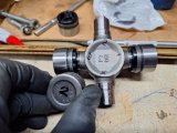
I really think Spicer makes the best u-joints, the machining and detail are beyond the average u-joint.

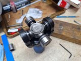
Not sure why, but the directions state to keep each cap on the trunion it came on.
I marked caps and trunions to keep them together at installation.
1000004421.heic.jpg

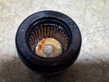
Besides an internal lip seal and external seal protector, the caps have a needle bearing retainer ring and a thrust washer at the bottom.
These are sealed u-joints, Spicer says do not add any more grease. The trunions are drilled for grease reservoirs.
1000004422.jpg

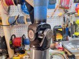
Yoke u-joint installed. Very nice smooth rotation on the installed u-joints.
1000004423.heic.jpg
1000004425.heic.jpg

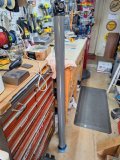
Rear u-joint installed, driveshaft was cleaned and painted before u-joint installation.
I used my press and a couple extra hands, the installation went very well.
Ready to go into the car.
1000004424.heic.jpg

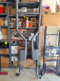
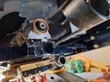
We pulled the exhaust out too, needs to be removed for transmission installation.
1000004426.heic.jpg
 
That's a good idea. Yes, there's available spots to install a filter.
I use mag filters in power steering return lines, they work very well.
 
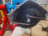
Tomorrow's set for installing the transmission. I prefilled the ATI converter and installed it, making very sure that it was fully seated. Very solid clunk at final seating.

I used high tech retention to make sure the converter stays in place while we're getting the transmission installed. It's actually a pretty good method, very secure.
2252024164545.jpg

I'm paranoid about getting it seated correctly lol. Has to engage with input shaft, pump stator and pump gear.

I also checked dimensions BEFORE installing the unit.
Face of converter lug to face of bellhousing = 1 1/16 in.
Face of flexplate pad to face of engine bellhousing = 29/32 in.
Difference is 5/32 in.
ATI states that converter pull-out should be 1/8 to 3/16 in. Looks like my clearance is right on the money, I'm happy with that.
 
Fail today......

As we started to bolt the transmission into place we would spin the converter to be sure all was ok.

As the transmission got to within 1/8 in of the engine, the converter would bind even though I knew it was properly seated. Tried a few times, ensuring the unit was aligned, but still a problem. Converter spins great in the transmission, very smooth.

So we pulled the transmission back and removed the converter from the transmission. Then tried to fit the converter hub into the crank. No luck, the hub appears to be machined oversize.

The crank opening measures out at 1.690 if I remember right - it's a stock 454 cast crank. The converter hub measured out at 1.705.

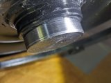
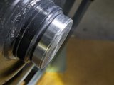
I'll contact ATI for help, but I'm concerned now about the pump gear tangs. In the picture below you can see the slight ledge on the hub that was made even without cranking down on the bellhousing bolts. That was a smooth hub. So that means the pressure that made this ledge was transfered to the pump gear.
IMG_20240326_195132.jpg
IMG_20240326_195150.jpg

My gut feeling is that the pump gear is probably OK because we never tightened everything down. As soon as the converter started binding and got unable to be turned by hand we stopped and loosened things back up. So I think the ledge was created by pressure from starting to tighten the transmission down and turning the converter while we were doing that. So we essentially ground that ledge into place.

Does anyone know the spec size rear opening on a 454 crankshaft? I can't seem to find it, just want to compare to what I measured. Not the inner pilot bearing hole size, the larger outer hole.

This wasn't a good day.....
 
Hopefully the mis-fit is getting resolved.
I first went back and checked everything - flexplate, pump gears, converter hub, etc for any obvious damage. I used my endoscope camera to get really close to the tangs on the pump gear. Everything looked fine.
I then put the converter back into the transmission and it turned just like before, very easily and smoothly.
I inspected and measured the end bore on the crankshaft - it looked good, no marks or gouges. Measured out to 1.7035 using several different tools.
I measured the old Continental converter hub that fit fine into this same crank, 1.702.
I measured the new ATI converter hub, 1.7045.

I contacted ATI, they were good in responding. Their spec on their hubs is 1.7025, so obviously something was wrong with the hub being 2 thou over. They said I could send it back. I thought about the timeframe to do this and decided to take the converter to a good small local machine shop. I did tell ATI that I was doing this, wasn't an issue with them on overall warranty.

I also took the Continental converter to the shop. Since I knew 100% that it fit, I asked them to simply match the ATI hub diameter to the Continental hub. $40 got this done today. I'm picking my stuff up tomorrow, they said they took a couple of thousands off, so the ATI should also now fit.

I didn't demand $40 from ATI, but they are sending me a variety of their apparel - I'm ok with this, I figure the dollars probably equal out. Mainly I wanted to resolve the issue quickly and accurately, meaning the hub was properly reduced in a lathe and not me trying to sand it down to fit.

I'll of course for sure verify converter fit into the crank tomorrow.

Edit - picked up the converter, and it fits fine into the crank. The shop did a nice job.
Good to go on the install.
 
Last edited:
its nice to see TCI gives a crap , listens to what your concerns are,
and takes customer concerns and potential issues seriously
many firms / vendors that won.t be in business very long,
seem to feel that once the check cashes its no longer their problem
everyone makes a few mistakes, but assuming you can ignore the issues if only a few customers complain is a huge mistake
 
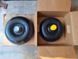
Here's the comparison of the 12" Continental converter and the new 10" ATI converter.
Nothing wrong with the Continental, I just needed a converter better suited to the new engine configuration.

1000004610.jpg

Grumpy, yes, I think ATI responded appropriately in telling me to send it back. I also think that doing a local fix was the best solution all around.
Machining the hub on a lathe was a lot better than me trying a garage fix. They took .0025 off the hub - it's an easy fit now into the crankshaft.
I'm happy with the result - of course the real proof will be in the converter performance!

We're getting together again tomorrow for TH400 Install Round 2.

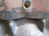
Edit - I thought I'd show the tag on the transmission. Decoding it shows as a 1982 build for a 454 Series 30 engine (FJ) then I think a serial number, or maybe that's a part of the vehicle VIN, not sure. I think the actual build date is cast into the case, its not on the tag.
As I recall, I bought it out of a wrecking yard in 1987. It had "84 truck" marked on it.
1000004590.jpg
 
Last edited:
when dealing with salvage yard parts you never know exactly what your dealing with
 
Installation .....

FINALLY.
It all went fine, with the converter hub issue addressed, the transmission bolted up to the engine and we could turn the converter the entire time.
We still took our time and eased them together, alternating sides and going over all the bolts a little at a time.
1000004630.heic.jpg

I added a couple of washers to get the converter at 1/8" pull-out from the pump. I had previously thought that I wouldn't need any spacers, evidently the real-world installation dictated otherwise. I could pull the converter out by hand so it's verified that it was fully seated and not binding.
1000004634.heic.jpg

Next task is to revise the driveline angle. If you looked at my Cam/Engine build thread, I had made new rear engine mounts.
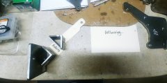
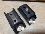
The original is on the left, just a single point attachment, one on each side that bolted through the transmission bellhousing into the block.
20230614_133417_HDR_resized.jpg

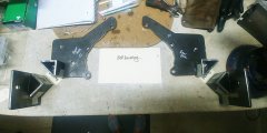
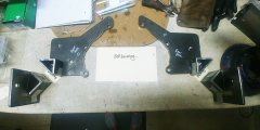
Here are the new ones, much sturdier attachment.
20230614_133348_HDR_resized.jpg

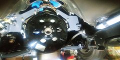
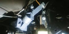
Installed, of course before the transmission was in.
To install the transmission, the engine was suspended, these mounts were removed and re-installed over the transmission bellhousing and into the engine block. They effectively "clamp" the two components together.
20230621_130057_HDR_resized.jpg

This all went very smoothly, but I think that the new mounts may have placed the engine slightly lower. This is causing the transmission tailshaft to be lower than I like and at a slight downward angle. I'm aware of proper driveline angles and I will first add a .25 in shim/spacer at the base of the rear engine mounts to raise the engine. I didn't do the math to calculate exact numbers, but I know this will raise the tailshaft height and angle.
It's not far off, but I will tweak the mounts as needed to get everything phased correctly. To be honest, it's not a complete surprise. Even though I tried to keep things the same dimensionally, changing the entire rear mount bracket setup was challenging.
1000004636.heic.jpg

One step at a time, at least the key transmission build and installation milestones have been accomplished!
 
I added a couple of washers to get the converter at 1/8" pull-out from the pump.
Did you consider that the washers may have different weights? It's probably overkill in my thinking. They are a fair distance from the center of rotation.

I'm aware of proper driveline angles and I will first add a .25 in shim/spacer at the base of the rear engine mounts to raise the engine.
Do you also have engine mounts on the side of the block? Where exactly are these spacers?
.
 
Rick, these were all hardened Gr8 washers from Bolt Depot vs local hardware. I've bought a few hundred dollars worth of nuts, bolts, washers, etc and all have been very good consistent qualify. I think any weight difference will be miniscule, not worth concern.

No side mounts on the engine, just front and rear mounts, essentially a four point support setup. All of my own fabrication.

If you look at the picture below, the shims would go between the triangular base of the motor plates and the side support. Not shown is the rubber biscuit that's also between these components. A bit hard to explain, but the end installation is very sturdy yet has rubber isolation. And by using shims I can adjust engine height.
20230614_133348_HDR_resized.jpg

The front mounts use rubber isolation pads so the engine isn't hard bolted to the frame anywhere.
 
Driveline positioning ..

I took a bunch of measurements and verified that the rear pinion is exactly centered in the frame and the tailshaft is 5/16 in slightly off center. Not enough to matter from what I've read.

The vertical positioning was another story. The tailshaft was much too low, angling downward, about 2 in too low. I was unable to get the crossmember/rear mount up under the unit. However, it was fixable and it was due to a slight variation in the new rear engine mounts I had fabricated.

The posts just above show the new rear engine mounts, as you can see they are more of a plate than just a single tab support.
The new rear mounts are essentially three components: the attachment plate, the rubber biscuit, and the frame bracket.
I had used the transmission itself to shape the plates, and I had used the old frame bracket measurements to locate and fabricate the new frame brackets, all out of thicker steel.
Here's the old mount just to show the three components.
5142023134749.jpg

As you can see, the single bolt tab was replaced by a three-bolt plate. Super strong.
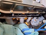
I routed the oil pressure sender away from the oil filter area for easier access.
20230621_130123_HDR_resized.jpg

But it looks like the new brackets ended up .25 in too low - it just shows you can't measure too much.
Here's the old tab lined up with the mockup of the new plate.
1000004680.heic.jpg

Looking closer you can see the difference in the bellhousing bolt hole.
1000004681.heic.jpg

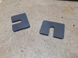
I made two .25 in thick shims.
1000004679.heic.jpg

And inserted them between the mount plate and the rubber biscuit on each side.
The biscuit looks sort of cracked in the picture, but it's fine, brand new.
1000004711.jpg

There's a threaded rod that's cast into the rubber mount, I had made a "special" tool to get a nut tightened inside that triangular part. Works great in the tight quarters.
33202414517.jpg

The difference that a .25 in shim made in the tailshaft vertical location was dramatic. Everything raised up to nearly level and looks good, however I will go through the entire driveline angle alignment process to ensure it's all phased correctly.

I did find that the tailshaft is still .75 in too low for the rear rubber mount. It's an easy crossmember modification to slightly lower the mounting tab to accomodate a standard 1.75 in thick TH400 rear rubber mount, about 10 bucks. I'm not doing a poly mount here.
1000004710.heic.jpg


1000004709.heic.jpg

However, I'm first going to check the driveline angles as it sits now before doing any modifications. Things are now positioned enough that I can put the driveshaft in and use the Spicer online angle program to see what I've got.

Edit - I checked left to right axis with an inclinometer and found that the driveline had a 3 degree tilt, higher at passenger side. I then made a 1/8 thick and a 3/16 thick shim. Back again with the engine hoist to swap shims on the passenger side engine mount. Ended up at 0 degrees using the 1/8 thick shim instead of the original 1/4 thick shim. I also checked at top of carb, same reading. Next will be driveline angles now that I know it's all sitting level, side to side.
 
Last edited:
Transmission cooler .....

Hugely important component - the radiator doesn't have transmission cooling lines built into it, so, just like before, I'm using a stand-alone cooler.
However, with the hp increase and the smaller torque converter, heat need to be addressed even more than before.

I did have a trans temp gauge before and I'll be using it again.

This time I'll be using a plate-type cooler that's larger than the fin-type cooler that was previously installed.
Plus getting rid of the dated red/blue fittings lol.

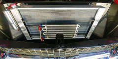
Here's what was in the car.
20200714_133641_HDR_resized.jpg

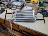
The support bracket only needs a very slight modification to incorporate the new larger 8 x 22 x 1.5 plate cooler.
The old cooler here was 8 x 12 x 1.
332024153248.jpg

The new cooler is shown here.

The other part of this is to also figure out best routing of the cooling lines - it looks like a combination of braided PTFE and 3/8 ni-copp will best suit the routing. All fittings will be 6AN.
 
Right now this last stretch is bouncing between this thread and my other Cam Research thread.
Reason is that I'm also needing to get other stuff done, such as shifter, wiring, gauges etc.

Another small piece of the transmission install puzzle, got a new rear mount today, about 10 bucks. I prefer rubber mounts over poly mounts

I noted the brand in case someone's looking for a th400 rear mount of a more universal application.
Old mount on the left, the main difference is that the threaded holes on the old one are for 3/8-16 bolts while the new mount uses 7/16-14 bolts. Not a big deal.
1000004736.heic.jpg

You'll see that new mount actually has three threaded holes. In my case I don't use the middle bolt.
 
Engine and Transmission Mounts......

These engine mounts have eaten my lunch! This comes under 10 steps backwards. I'll try to explain, but it all comes under building cars, expect to re-do things.

In my car, the rear engine mounts are not only primary supports for the drivetrain, but they also are used to set the angle of the drivetrain.
I kept fighting problems trying to get the transmission back into its former location, without the need to modify the crossmember. This was a good setup for about 35 years, with no driveline issues.

It was problematic using the engine hoist to hold the engine as the lift bar would hit the hood before I could get the drivetrain lifter to the proper (original) height. I did not want to remove the hood again, so I decided I would make something to support the engine from below at the rear mounts. This would also help to make small adjustments to get the drivetrain angles within spec.

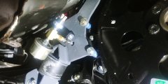
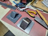
Back to these pictures for reference - these are the rear engine mount plates as installed.
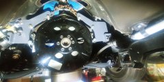
20230621_130057_HDR_resized.jpg

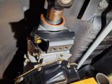
And here's one of the side supports that bolts through the frame. The rear plates sit on top of the rubber bushing.
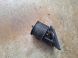
1000004804.heic.jpg

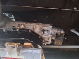
Here's the transmission finally sitting on the crossmember with the new rear mount.
As you can see, plenty of driveshaft clearance, even for the handbrake cabling.
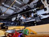
1000004816.heic.jpg

You can see clearance between the driveshaft tube and the handbrake cable equalizer (cables are tensioned).
This is just how it used to be, never any rubbing.
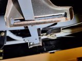
1000004817.heic.jpg

But the problem in using shims to raise the engine height was that there was not going to be much thread left on the rubber bushing after shim and rear plate thickness. So I was essentially trying to fix symptoms and not the root cause of the problem.
This was just a .125 shim, add another .187 for the engine plate, doesn't leave much. And at least a .25 shim was needed.
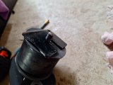
1000004809.heic.jpg

I realized that I needed to change both side supports for the engine mount plates. They weren't the right angle and they were too low.
Rather than monkey around with the current supports, I decided to make new ones, but this time since the engine was in the car, I wanted to be able to support the engine and still be able to adjust it slightly. This would also allow me to get the side supports right.

Bear with me, I'm only slightly crazy.

So I made an extra vertical bracket for each side. The passenger side has an opening for the starter cable.
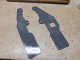
3122024212136.jpg

This is the idea. These vertical brackets bolt into the rear engine mount plates and are left in place. They don't interfere with the headers and are above any possible objects on the road. There's a lot of other stuff that would hit first.
These brackets are drilled for attachment to a sturdy wooden support that I made. The wooden support in turn sits on a scissor jack, which is used to adjust height up or down and will retain its position.
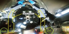
Supports.jpg

This is the passenger side vertical bracket bolted onto the wooden support.
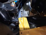
1000004807.jpg

This is the passenger side vertical bracket bolted onto the wooden support structure.
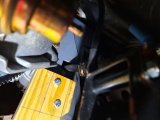
1000004808.jpg

And the entire assembly as a first test on the scissor jack. I've since added a wider base, but even this setup was very solid. Remember also that there is a transmission jack in place along with the rear crossmember and the front engine mounts. The amount of load on this isn't even close to bending stress on the wooden support.
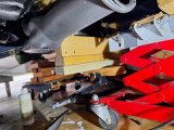
1000004806.heic.jpg

Despite the extra work, this gave me a solid base of support and adjustability.

Hindsight is a wonderful thing - if I had the engine out again, I'd probably make my own side mounts, but it is what it is. The idea is that once I get this stuff squared away, I won't need to mess with it again.
 
Engine and Transmission Mounts ....

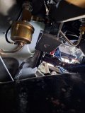
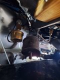
I did need to drop the drivers side header to get clear access to the side supports. Didn't need to remove it, what you see here was enough to get access to measure.
Haven't gotten to the passenger side yet.
1000004810.heic.jpg

This is the base of the driver side rear engine mount plate.
1000004811.heic.jpg

Same plate with the bushing in place.
The picture makes for an odd angle but this gave me the ability to measure for the new side support brackets, right from the bottom of the bushing to the frame side rails, in terms of both height and angle.
1000004813.heic.jpg

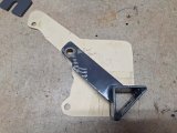
Recently made bracket on the left vs new bracket on the right.
They look similar, but there's enough difference in the angle and the height to need a new bracket.
1000004815.heic.jpg

Besides needing more height, I didn't get the angle right on the first one. I had made the bracket vertical, but the installed engine sits at a slight angle. Since I'm able to measure with the engine in place, I can get that angle correct for both side supports. This will allow the engine plates to sit squarely onto the side supports.

Oh, and here's the new transmission mount, the easiest part of this whole fiddly conglomeration ;)
1000004805.heic.jpg
 
Back
Top