You are using an out of date browser. It may not display this or other websites correctly.
You should upgrade or use an alternative browser.
You should upgrade or use an alternative browser.
TH400 Amateur Build
- Thread starter TXChevy
- Start date
Forward Clutch.....
The cushion plates are thinner and are usually not used with a steel piston that has the single vertical spacer, like the one on the right in the picture. They're usually recommended to be replaced in any sort of performance build.
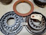
The wave plates don't impact the speed of the shift, that's a function of the valve body fill circuits, pump pressure, etc. The wave plates help to absorb the impact of the shift (piston movement), especially at low speeds. When done, this unit should be set up for strong quick shifts but not to the point where the car jerks annoyingly at low speed shifts.
The cushion plates are thinner and are usually not used with a steel piston that has the single vertical spacer, like the one on the right in the picture. They're usually recommended to be replaced in any sort of performance build.

The wave plates don't impact the speed of the shift, that's a function of the valve body fill circuits, pump pressure, etc. The wave plates help to absorb the impact of the shift (piston movement), especially at low speeds. When done, this unit should be set up for strong quick shifts but not to the point where the car jerks annoyingly at low speed shifts.
Intermediate Clutchpack....
Feels like I'm on Part 20 of the clutchpacks
OK, so after hours of sorting through info and getting extra advice, here's what the final intermediate installation ended up being.
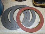
First, I've now got an assortment of Raybestos frictions for the clutchpacks. All are fine for my use, so it's more personal preference at this point. Generally speaking from Raybestos info, the smooth tan are OEM level material, the red waffle are Stage 1, and the green waffle are GPZ high energy. I take this to be related to the aggressiveness of the friction material.
For the intermediate, I went with the red (thicker) waffle frictions, always trying to use the thicker frictions whenever possible.
And again, here's the ATSG diagram.
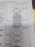
Note that the diagram shows a flat steel on a wave plate (if used).
But looking in the highlighted text it's clearly stated that you can use a friction on a wave.
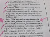
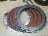
Here's the components of the final install of the intermediate clutch pack:
.070 wave
(3) .092 frictions
(2) .098 flat steels
.325 pressure plate
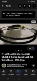
.086 spiral lock
Clearance = .045
Spec clearance = .030 to .070
Spiral lock used instead of a snap ring
Installed, you can see the spiral lock locates right below the tab on the Sonnax case saver.
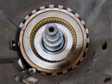
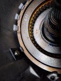
And a very nice clutch apply.
Something to double check is that the scarf-cut seals weren't damaged and the ends stayed aligned during all the set-up fiddling with the clutch pack.
Added a bit more blue lube to ensure the seals are solidly retained.
This is all now ready for the direct drum, note the second seal left out for the dual feed modification.
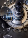
Feels like I'm on Part 20 of the clutchpacks

OK, so after hours of sorting through info and getting extra advice, here's what the final intermediate installation ended up being.
First, I've now got an assortment of Raybestos frictions for the clutchpacks. All are fine for my use, so it's more personal preference at this point. Generally speaking from Raybestos info, the smooth tan are OEM level material, the red waffle are Stage 1, and the green waffle are GPZ high energy. I take this to be related to the aggressiveness of the friction material.
For the intermediate, I went with the red (thicker) waffle frictions, always trying to use the thicker frictions whenever possible.

And again, here's the ATSG diagram.

Note that the diagram shows a flat steel on a wave plate (if used).
But looking in the highlighted text it's clearly stated that you can use a friction on a wave.

Here's the components of the final install of the intermediate clutch pack:
.070 wave
(3) .092 frictions
(2) .098 flat steels
.325 pressure plate
.086 spiral lock
Clearance = .045
Spec clearance = .030 to .070

Spiral lock used instead of a snap ring

Installed, you can see the spiral lock locates right below the tab on the Sonnax case saver.


And a very nice clutch apply.
Something to double check is that the scarf-cut seals weren't damaged and the ends stayed aligned during all the set-up fiddling with the clutch pack.
Added a bit more blue lube to ensure the seals are solidly retained.
This is all now ready for the direct drum, note the second seal left out for the dual feed modification.

Forward Clutch .....
This is my assortment of .080 clutches for the forward and direct clutch packs.
I decided to go with the green waffle frictions in both packs.
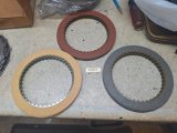
You're supposed to clean up the Kolene steels before use, and I can see why - the heat treat surface coating residue is pretty rough.
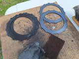
Here's my additional parts:
- Sonnax steel forward hub
- Sonnax heavy gauge spring retainer
- spiral lock for the spring retainer
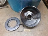
The rebuild kit includes bronze face bushings for the hub vs oem plastic
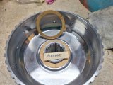
Component lineup for the forward:
.060 wave
(5) .080 green waffle frictions
(4) .079 flat steels
Pressure plate
.061 snap ring
Clearance = .038-.040
Spec clearance = .030 to .050
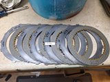
This was the aluminum piston I got to replace the stock steel piston, has a better "shelf" to bear against the clutch pack.
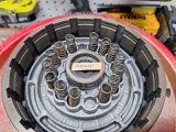
Spring retainer assembled.
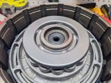
I put the clutches in to soak, but the forward is essentially done.
This is my assortment of .080 clutches for the forward and direct clutch packs.
I decided to go with the green waffle frictions in both packs.

You're supposed to clean up the Kolene steels before use, and I can see why - the heat treat surface coating residue is pretty rough.

Here's my additional parts:
- Sonnax steel forward hub
- Sonnax heavy gauge spring retainer
- spiral lock for the spring retainer

The rebuild kit includes bronze face bushings for the hub vs oem plastic

Component lineup for the forward:
.060 wave
(5) .080 green waffle frictions
(4) .079 flat steels
Pressure plate
.061 snap ring
Clearance = .038-.040
Spec clearance = .030 to .050

This was the aluminum piston I got to replace the stock steel piston, has a better "shelf" to bear against the clutch pack.

Spring retainer assembled.

I put the clutches in to soak, but the forward is essentially done.
Direct clutch ......
This one kind of ran me around in circles on the final clearance until I realized that I needed to be working with 4L80e drum clearance spec instead of TH400 drum spec. Even though they both fit, they measure out differently.
Once again, Nick's Transmission video (and his advice) helped me out.
I used the measurement procedure he outlined, and it worked quite well.
I've mentioned that internal ledge that the pressure plate sits on before. In the picture the top friction has been swapped with a steel so that I could get solid measurements.
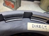
In this case, the dial caliper was used to measure the distance from the ledge to the top of the steel. This was done in four places, with an average of .030.
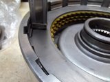
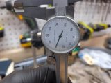
Next a dial indicator was used to measure the distance the pressure plate moved when it was pulled up against the snap ring.
Average distance was .033.
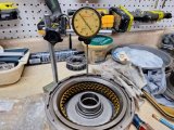
This gave a total clearance (travel) measurement of .063. Spec clearance on a 4L80e drum is .050 to something like .112+, so this is fine. I also double checked between pressure plate and clutch pack with a feeler gauge and verified the clearance.
Note - seems that most builders go for .050 to .075 on the clearance, so I should be ok.
The 4L80e drum component setup:
.087 wave
(5) .092 steels
(5) .080 green waffle frictions
.405 pressure plate
.061 snap ring
Clearance = .063
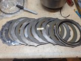
Same as the forward, frictions are soaking in some fluid, but this one is also ready for final install. I also still have to install the spring retainer cage assembly and spiral lock.
I then paid some attention to the forward band.
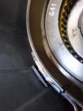
Remember that we have the Sonnax case saver that's sitting over the anchor pin of the band. Instructions state that a bit of the band tab may need to be ground in order to ensure the band isn't pushed too far into the unit - needs to allow free movement of the drum.
It was a bit crooked anyway.
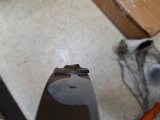
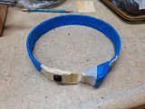
I wrapped the band, so no metal debris got into the lining.
Didn't take much. Fits nice and flush against the case saver, with still enough pin retention.
This one kind of ran me around in circles on the final clearance until I realized that I needed to be working with 4L80e drum clearance spec instead of TH400 drum spec. Even though they both fit, they measure out differently.
Once again, Nick's Transmission video (and his advice) helped me out.
I used the measurement procedure he outlined, and it worked quite well.
I've mentioned that internal ledge that the pressure plate sits on before. In the picture the top friction has been swapped with a steel so that I could get solid measurements.

In this case, the dial caliper was used to measure the distance from the ledge to the top of the steel. This was done in four places, with an average of .030.


Next a dial indicator was used to measure the distance the pressure plate moved when it was pulled up against the snap ring.
Average distance was .033.

This gave a total clearance (travel) measurement of .063. Spec clearance on a 4L80e drum is .050 to something like .112+, so this is fine. I also double checked between pressure plate and clutch pack with a feeler gauge and verified the clearance.
Note - seems that most builders go for .050 to .075 on the clearance, so I should be ok.
The 4L80e drum component setup:
.087 wave
(5) .092 steels
(5) .080 green waffle frictions
.405 pressure plate
.061 snap ring
Clearance = .063

Same as the forward, frictions are soaking in some fluid, but this one is also ready for final install. I also still have to install the spring retainer cage assembly and spiral lock.
I then paid some attention to the forward band.
Remember that we have the Sonnax case saver that's sitting over the anchor pin of the band. Instructions state that a bit of the band tab may need to be ground in order to ensure the band isn't pushed too far into the unit - needs to allow free movement of the drum.
It was a bit crooked anyway.

I wrapped the band, so no metal debris got into the lining.

Didn't take much. Fits nice and flush against the case saver, with still enough pin retention.

Low/Reverse Band and Servo ......
This could probably wait until the entire internal geartrain is done, but I decided to get the rear servo installed now. I wanted to be sure that if there was something that came up, I only had to disassemble half of the unit
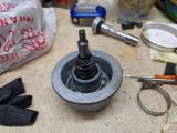
Here's the rear servo with accumulator, with all new seals installed. No changes to any of the springs.
There's a lot of info on how to measure or at least tell if the rear band is dragging.
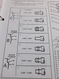
The ATSG manual shows the different pin configurations - mine is pin #3 with the dual bands.
This Nick's Transmission video was helpful to figure out what needed to be measured and how.
Starts at 20:00 talking about the rear servo.
Additional info from CK Performance instructions on measuring the stroke length was also referenced, here's a link.
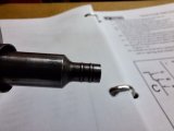
The black mark is where the reference is taken to measure servo travel into the bore. I used the servo without any seals, and without the accumulator/spring. In my case, I was able to push down a bit over 1/8". Had to eyeball it since I wasn't able to keep the servo pushed in with just one hand, even with the single spring. I really had to push hard to get enough reverse band apply to stop the gearset.
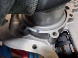
I think it's all ok, but I'm mulling over making the partial reverse servo cover tool to really nail down the stroke length.
There's no drag when the servo is in the "rest" (non-apply) position, but I'm wondering if some additional pin length may be needed.
It did all work with the air check though so I'll just let the thought here simmer for a while.
Anyway, the perimeter square cut rubber seal at the servo piston needed replacement, as did the teflon seals on the accumulator.
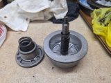
New square-cut seal for the piston installed easily.
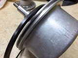
The accumulator was a bit more fiddly, as it had teflon seals. The rebuild kit included steel rings, but I had also bought a complete teflon seal kit for the transmission as well. I've already used teflon scarf-cut seals on the center support stator, these are solid ring seals on the accumulator.
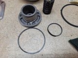
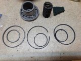
Below, from left to right, are solid ring teflon seals, steel ring seals, and the original teflon solid ring seals. As mentioned, I opted to use new solid ring teflon seals.
This could probably wait until the entire internal geartrain is done, but I decided to get the rear servo installed now. I wanted to be sure that if there was something that came up, I only had to disassemble half of the unit
Here's the rear servo with accumulator, with all new seals installed. No changes to any of the springs.

There's a lot of info on how to measure or at least tell if the rear band is dragging.
The ATSG manual shows the different pin configurations - mine is pin #3 with the dual bands.


This Nick's Transmission video was helpful to figure out what needed to be measured and how.
Starts at 20:00 talking about the rear servo.
Additional info from CK Performance instructions on measuring the stroke length was also referenced, here's a link.
The black mark is where the reference is taken to measure servo travel into the bore. I used the servo without any seals, and without the accumulator/spring. In my case, I was able to push down a bit over 1/8". Had to eyeball it since I wasn't able to keep the servo pushed in with just one hand, even with the single spring. I really had to push hard to get enough reverse band apply to stop the gearset.

I think it's all ok, but I'm mulling over making the partial reverse servo cover tool to really nail down the stroke length.
There's no drag when the servo is in the "rest" (non-apply) position, but I'm wondering if some additional pin length may be needed.
It did all work with the air check though so I'll just let the thought here simmer for a while.
Anyway, the perimeter square cut rubber seal at the servo piston needed replacement, as did the teflon seals on the accumulator.

New square-cut seal for the piston installed easily.

The accumulator was a bit more fiddly, as it had teflon seals. The rebuild kit included steel rings, but I had also bought a complete teflon seal kit for the transmission as well. I've already used teflon scarf-cut seals on the center support stator, these are solid ring seals on the accumulator.

Below, from left to right, are solid ring teflon seals, steel ring seals, and the original teflon solid ring seals. As mentioned, I opted to use new solid ring teflon seals.

Low Reverse Band and Servo ......
The original seals looked ok but were a bit hardened after many years.
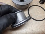
I used the basic teflon seal install process, the new seals were placed in hot water for a few minutes to help get them a bit more pliable.
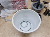
I then carefully stretched the new seals into place. Note that they are square-cut seals so they need to be installed without twisting.
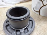
However, they were then too loose, and needed to be re-sized back into shape.
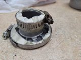
Simple seal compression using a couple of hose clamps just snugged into place.
I left the clamps in place for about an hour.
The accumulator inserted easily into the servo piston and case bore and I anticipate that the new seals will sort of fill out slightly, now that they are in place.
Next was to ensure that the servo cover gasket and cover were correctly oriented.
You can see how the gasket needs to mimic the case feed opening, and how the cover is shaped to conform to the gasket.
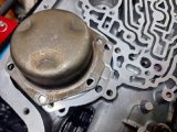
The cover/gasket were installed, using a criss-cross pattern to torque to 18 ft/lb.
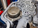
But there was a bit of a problem.
You can see the different head cover bolt at the bottom of the picture. As I was tightening the original bolt, the torque reading started to decrease from 18 to about 14 ft/lbs. Not good, that's a sign of the aluminum case threads starting to pull. It still feels plenty tight just using a rachet, but I may need to go back and use a helicoil in this location. I did use a slightly longer bolt to try to get to the bottom threads, but I'm not sure what the long term may be. I don't want a leak that can impact reverse band application.
Air check was good.
This is the fluid port for the reverse servo.
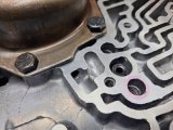
Air is applied here to activate the servo/engage the reverse band.
There's a lot of spring tension at the accumulator/servo, it took a minimum of 35 psi to activate the servo, but it all sounded healthy, a solid clunk.
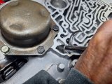
The geartrain was rotated before and after servo installation, and also to verify the reverse band activated and grabbed the geartrain.
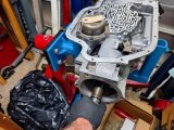
So that's done, but there's a couple of clouds that will need to be resolved - true servo travel and a threaded hole.
Not really the end of the world, I'll probably go back and mess with this some more.
But in the meantime, the rest of the geartrain assembly can still go on.
The original seals looked ok but were a bit hardened after many years.

I used the basic teflon seal install process, the new seals were placed in hot water for a few minutes to help get them a bit more pliable.

I then carefully stretched the new seals into place. Note that they are square-cut seals so they need to be installed without twisting.
However, they were then too loose, and needed to be re-sized back into shape.

Simple seal compression using a couple of hose clamps just snugged into place.
I left the clamps in place for about an hour.

The accumulator inserted easily into the servo piston and case bore and I anticipate that the new seals will sort of fill out slightly, now that they are in place.
Next was to ensure that the servo cover gasket and cover were correctly oriented.
You can see how the gasket needs to mimic the case feed opening, and how the cover is shaped to conform to the gasket.

The cover/gasket were installed, using a criss-cross pattern to torque to 18 ft/lb.

But there was a bit of a problem.
You can see the different head cover bolt at the bottom of the picture. As I was tightening the original bolt, the torque reading started to decrease from 18 to about 14 ft/lbs. Not good, that's a sign of the aluminum case threads starting to pull. It still feels plenty tight just using a rachet, but I may need to go back and use a helicoil in this location. I did use a slightly longer bolt to try to get to the bottom threads, but I'm not sure what the long term may be. I don't want a leak that can impact reverse band application.
Air check was good.
This is the fluid port for the reverse servo.

Air is applied here to activate the servo/engage the reverse band.
There's a lot of spring tension at the accumulator/servo, it took a minimum of 35 psi to activate the servo, but it all sounded healthy, a solid clunk.

The geartrain was rotated before and after servo installation, and also to verify the reverse band activated and grabbed the geartrain.

So that's done, but there's a couple of clouds that will need to be resolved - true servo travel and a threaded hole.
Not really the end of the world, I'll probably go back and mess with this some more.
But in the meantime, the rest of the geartrain assembly can still go on.
Upgrades ......
Here's the latest list, includes stuff that you generally want to have ......
EDITED 3-1-2024
- aluminum 2-3 accumulator piston (replace plastic version)
- Sonnax pump regulator kit with spring
- Sonnax Torrington bearing kit (used at 3 locations in transmission)
- Spiral lock for intermediate clutchpack
- add round pan magnet (didn't have one!)
- 4R70W low roller clutch
- dual feed mod for direct drum - includes cup plug at reverse feed, delete #2 stator seal
- 4L80e direct drum assembly, piston, return springs, 34 element sprag, spiral retainer (all good used OEM)
- Spiral lock for direct drum
- Sonnax forward clutch heavy duty steel hub
- scarf cut sealing ring kit (vs oem steel rings)
- new 4L80e center support feed/retaining bolt (cut to th400 bolt length)
- Sonnax heavy duty spring retainer for forward piston
- Six (vs three) heavy duty return springs for intermediate piston
- Sonnax anti-walk/rollerized output case bushing
- Sonnax case saver
- new bushings
- new kickdown wire case connector
- new kickdown solenoid
- aluminum (flat) forward clutch piston
- heavy duty (red faced) forward band
Overall Rebuild Cost:
All parts/upgrades = $1147
Converter (est) = $569
Total = $1716
I've also started to talk with torque converter manufacturers that from research are generally known for quality products. I've got all of Grumpy's links on converter selection as well and have read through them. I am not interested in B&M, TCI and others that have too many failure issues.
The converter I was using (no issues with it) was a Continental 2200 rated stall converter.
I'm not going to re-use it for a couple of reasons:
- I can't clean it and I know it has debris inside of it. I don't want that to circulate into the fresh transmission
- The engine power/tq characteristics have been substantially changed and I want the transmission/converter to make the most of those changes.
So far, I've gotten with Hughes and ATI, more to come in a later post.
Direct Drum Final Install .....
First was to get the new forward band into place. I had decided to swap the new band that came in the kit with what is termed a heavy duty Raybestos band. The lining is the difference, the Raybestos band lining is slightly thicker and the weld points on the anchors look sturdier.
Band went into place very easily. I had taken a very small amount off of the band anchor to accommodate the Sonnax case saver depth.
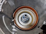
Fit was very good.
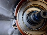
Spring retainer and spiral lock were double checked.
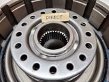
The sprag element was also checked yet again.
Note - I had put some blue lube on the bottom race, but there is no bushing that goes between the direct drum and the intermediate/center support.
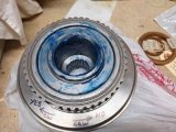
Here's the final lineup as mentioned earlier, clearance of .063
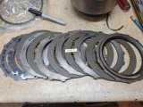
Installed into the case. No drag from the band.
It takes some wiggling and turning to get the sprag splines aligned into the intermediate clutch pack. There's a definite hard feel when the drum is fully seated - you can hear and feel a solid clunk.
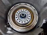
And as a check, there should be no movement of the direct clutch pack when air is put into the intermediate clutch.
If the direct moves at all, then it's not fully seated.
First was to get the new forward band into place. I had decided to swap the new band that came in the kit with what is termed a heavy duty Raybestos band. The lining is the difference, the Raybestos band lining is slightly thicker and the weld points on the anchors look sturdier.
Band went into place very easily. I had taken a very small amount off of the band anchor to accommodate the Sonnax case saver depth.

Fit was very good.

Spring retainer and spiral lock were double checked.

The sprag element was also checked yet again.
Note - I had put some blue lube on the bottom race, but there is no bushing that goes between the direct drum and the intermediate/center support.

Here's the final lineup as mentioned earlier, clearance of .063

Installed into the case. No drag from the band.
It takes some wiggling and turning to get the sprag splines aligned into the intermediate clutch pack. There's a definite hard feel when the drum is fully seated - you can hear and feel a solid clunk.

And as a check, there should be no movement of the direct clutch pack when air is put into the intermediate clutch.
If the direct moves at all, then it's not fully seated.
Forward drum final install.......
Here's the drum with piston and spring retainer installed.
As mentioned, the piston is aluminum version with the double rail vs the oem single rail steel piston.
The retainer is Sonnax heavy duty (heavier gauge steel) over standard return springs, held in place with a spiral lock.
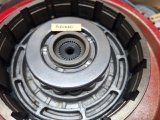
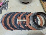
Here's the lineup for the forward. Clearance of .042
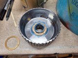
Forward hub is Sonnax steel vs oem cast iron, using bronze faced bushings on each side.
Note - the bushings are different for each side, but can only be installed in one position, so no worries.
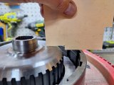
You have to work the hub (don't forget the bushing!) into the clutches.
Just to be 100% sure I took a general measurement of the hub fully seated without the clutches.
Then a quick check after the hub was installed.
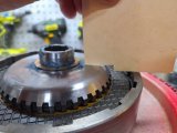
Fully assembled, and ready to install into the direct drum. Be sure you use blue lube to retain the bushing as you turn this upside down for installation.
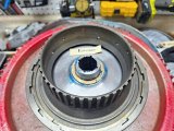
Forward drum installed and fully seated.
Note - this takes a considerable amount of wiggling and turning to get fully seated. You will feel a solid stop when it's in all the way.
If it's not fully seated, the pump will not install properly and you will have zero endplay at the input shaft. Be careful - if the pump is not seating properly don't force things! Remove the pump and keep fiddling with the forward drum.
Here's the drum with piston and spring retainer installed.
As mentioned, the piston is aluminum version with the double rail vs the oem single rail steel piston.
The retainer is Sonnax heavy duty (heavier gauge steel) over standard return springs, held in place with a spiral lock.

Here's the lineup for the forward. Clearance of .042

Forward hub is Sonnax steel vs oem cast iron, using bronze faced bushings on each side.
Note - the bushings are different for each side, but can only be installed in one position, so no worries.

You have to work the hub (don't forget the bushing!) into the clutches.
Just to be 100% sure I took a general measurement of the hub fully seated without the clutches.

Then a quick check after the hub was installed.

Fully assembled, and ready to install into the direct drum. Be sure you use blue lube to retain the bushing as you turn this upside down for installation.

Forward drum installed and fully seated.
Note - this takes a considerable amount of wiggling and turning to get fully seated. You will feel a solid stop when it's in all the way.
If it's not fully seated, the pump will not install properly and you will have zero endplay at the input shaft. Be careful - if the pump is not seating properly don't force things! Remove the pump and keep fiddling with the forward drum.

Pump (Almost) Final Install .......
Before moving into the pump installation, the pump halves need to be aligned.
You can use a large specialty clamp or band - I elected to use another acceptable method, which is to use the case itself for alignmnent.
I had left myself a note back when I had cleaned up the pump.
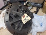
The pump is placed upside down into the case, without gasket or o-ring. Pump body bolts are barely finger tight to allow movement.
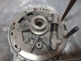
Here you can see the pump in the case with a number of bolts and dowels aligning the pump halves.
Then the bolts are torqued to 18 ft/lbs in a cross pattern.
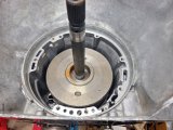
Next important step was to figure out the input shaft endplay. I had already done the same for the output shaft.
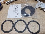
There were three plastic selective pump thrust washers in the rebuild kit, but I had also bought a complete set.
Selectives come in either number or letter series, and their thicknesses can vary a bit, so each number/letter is given a range.
The three selectives shown were letters A (.072), C (.094), and E (.117). The selectives in the bag covered letters A to E.
The pump gasket is about .0015 uncompressed, and about .0012 when compressed.
That number can be added to the selective washer thickness if you choose to install the pump without gasket/oring. It's a bit easier that way, but your final measurement should be verified after final pump installation.
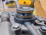
Here's a black plastic selective in place along with new teflon scarf-cut pump stator seals.
I had left out the seals and pump o-ring while I was trying different selectives getting to the right endplay measurement.
Note - the scarf cuts are 90 degrees away from that fluid feed hole, one to the right, one to the left, so that the cuts are 180 degrees away from each other.
Spec endplay is .007 to .024, generally a tighter measurement is preferred to allow for break-in and future wear.
The original input shaft endplay was .029, very loose. The original plastic selective bushing was .093 thickness.
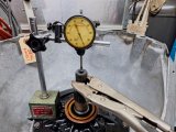
This is the general measurement setup - the vice-grips help to grip the input shaft when pulling up.
Assuming that the endplay would be tightened up with all the new parts and bushings, I tried a "C" selective (.094).
Measurement was taken with pump installed on gasket, bolts tightened - came out to .010, which is ideal. I think that the gasket will compress a bit further and that after break-in there will be a bit more clearance added. I'm happy with this setting.
Pump o-ring was installed, and pump set into place but not as final installation......
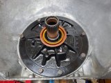
The reason that I can't call this final is due to 6 little washers .....
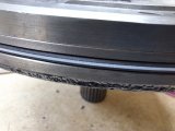
In this unit, this pump takes 6 bolts with sealing washers. Some pump bolts take an o-ring, but these are rubber coated sealing washers.
I can't re-use them and I want to use the right parts, so I ordered a new set. You can see the old ones were in crummy condition.
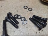
All in all, that's minor, when I get the new washers, I'll just loosen the bolts, install the washers, and re-torque (18 ft/lbs).
Glad to have the geartrain in place and measured out - now ready to move on to the valve body and peripherals.
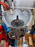
Before moving into the pump installation, the pump halves need to be aligned.
You can use a large specialty clamp or band - I elected to use another acceptable method, which is to use the case itself for alignmnent.
I had left myself a note back when I had cleaned up the pump.

The pump is placed upside down into the case, without gasket or o-ring. Pump body bolts are barely finger tight to allow movement.
Here you can see the pump in the case with a number of bolts and dowels aligning the pump halves.
Then the bolts are torqued to 18 ft/lbs in a cross pattern.

Next important step was to figure out the input shaft endplay. I had already done the same for the output shaft.
There were three plastic selective pump thrust washers in the rebuild kit, but I had also bought a complete set.
Selectives come in either number or letter series, and their thicknesses can vary a bit, so each number/letter is given a range.
The three selectives shown were letters A (.072), C (.094), and E (.117). The selectives in the bag covered letters A to E.

The pump gasket is about .0015 uncompressed, and about .0012 when compressed.
That number can be added to the selective washer thickness if you choose to install the pump without gasket/oring. It's a bit easier that way, but your final measurement should be verified after final pump installation.
Here's a black plastic selective in place along with new teflon scarf-cut pump stator seals.
I had left out the seals and pump o-ring while I was trying different selectives getting to the right endplay measurement.
Note - the scarf cuts are 90 degrees away from that fluid feed hole, one to the right, one to the left, so that the cuts are 180 degrees away from each other.

Spec endplay is .007 to .024, generally a tighter measurement is preferred to allow for break-in and future wear.
The original input shaft endplay was .029, very loose. The original plastic selective bushing was .093 thickness.
This is the general measurement setup - the vice-grips help to grip the input shaft when pulling up.

Assuming that the endplay would be tightened up with all the new parts and bushings, I tried a "C" selective (.094).
Measurement was taken with pump installed on gasket, bolts tightened - came out to .010, which is ideal. I think that the gasket will compress a bit further and that after break-in there will be a bit more clearance added. I'm happy with this setting.
Pump o-ring was installed, and pump set into place but not as final installation......


The reason that I can't call this final is due to 6 little washers .....
In this unit, this pump takes 6 bolts with sealing washers. Some pump bolts take an o-ring, but these are rubber coated sealing washers.
I can't re-use them and I want to use the right parts, so I ordered a new set. You can see the old ones were in crummy condition.

All in all, that's minor, when I get the new washers, I'll just loosen the bolts, install the washers, and re-torque (18 ft/lbs).
Glad to have the geartrain in place and measured out - now ready to move on to the valve body and peripherals.

Valve Body .......
First business was to remove all valves and give the VB a thorough cleaning.
Background - the only changes I had made to this transmission was the installation of a Continental converter back in 1990 and a B&M shift kit before that sometime. As I recall, the operation and shifts were pretty good.
Ready to start. Those are the removed governor tubes - same size, the only difference is that the return has a screen at the valve body.
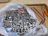
I was going to replace the plastic 2-3 Accumulator with an aluminum version, but I was really surprised to see that the 2-3 Accumulator had been disabled. Not a bad thing but I honestly don't remember doing it lol.
Spring had been removed and the fluid feed port had been threaded for an insert.
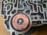
I removed the accumulator and then identified the valves to be removed/cleaned.
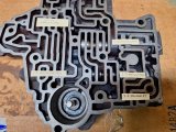
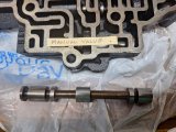
If you're wondering about just removing and re-installing a valve body, thinking it looks ok, this is after the third cleaning.
There's a LOT of debris that gets trapped inside, removing the valves is really the only way to thoroughly clean everything.
This took a number of cleanings, then compressed air to blow out all the passages.
The bits and pieces in the pan aren't from the VB, but that fluid is full of metallic/clutch debris from many years of use.
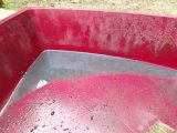
I used the ATSG manual and took pics of all the valves removed to be sure the installation sequence would be correct.
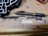
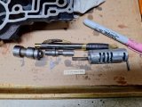
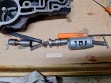
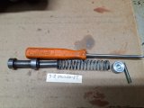
First business was to remove all valves and give the VB a thorough cleaning.
Background - the only changes I had made to this transmission was the installation of a Continental converter back in 1990 and a B&M shift kit before that sometime. As I recall, the operation and shifts were pretty good.
Ready to start. Those are the removed governor tubes - same size, the only difference is that the return has a screen at the valve body.

I was going to replace the plastic 2-3 Accumulator with an aluminum version, but I was really surprised to see that the 2-3 Accumulator had been disabled. Not a bad thing but I honestly don't remember doing it lol.
Spring had been removed and the fluid feed port had been threaded for an insert.

I removed the accumulator and then identified the valves to be removed/cleaned.


If you're wondering about just removing and re-installing a valve body, thinking it looks ok, this is after the third cleaning.
There's a LOT of debris that gets trapped inside, removing the valves is really the only way to thoroughly clean everything.
This took a number of cleanings, then compressed air to blow out all the passages.
The bits and pieces in the pan aren't from the VB, but that fluid is full of metallic/clutch debris from many years of use.

I used the ATSG manual and took pics of all the valves removed to be sure the installation sequence would be correct.


Valve Body .....
While the valve body was apart, I also cleaned up the casting a bit, just to make it look a little tidier.
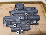
I also gave the case side a very light going over with 600 grit on a flat stone.
Only enough to ensure there were no low/high spots.
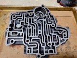
I used the good old scotchbrite on a wire to give the valve bores a quick clean.
Nothing crazy, just a light touch is all that's needed.
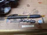
New aluminum 2-3 Accumulator to replace the oem brittle plastic accumulator.
For some reason I had used a bunch of washers under the C-clip, I guess to ensure the accumulator wouldn't move, but if the feed is plugged it's not going to move. So all those washers weren't needed. I am going to replace the home-made set screw with an allen set screw for no other reason than it looks better.
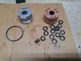
The 2-3 Accumulator and the piston for the forward band each got new teflon rings.
Same process as the other one-piece rings, put into hot water, stretch into place, then used some electrical tape to help reshape them.
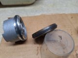
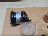
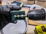
Valves were all given a touch of scotchbrite,, where feasible I used the drill to spin the valve. By "feasible" I mean where the valve could be gripped by the drill on a non-land section.
Cleaned, all valves re-installed, new aluminum 2-3 accumulator.
Each valve was double checked for the proper orientation and free movement in the bore.
That's a combination of transmission fluid and WD-40 on the valve body - it will get wrapped up in the bag until time to install.
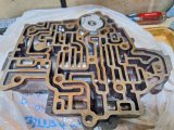
Next I'll be doing some investigation on the separator plate to see what had been done in regards to the B&M shift kit.
While the valve body was apart, I also cleaned up the casting a bit, just to make it look a little tidier.

I also gave the case side a very light going over with 600 grit on a flat stone.
Only enough to ensure there were no low/high spots.

I used the good old scotchbrite on a wire to give the valve bores a quick clean.
Nothing crazy, just a light touch is all that's needed.

New aluminum 2-3 Accumulator to replace the oem brittle plastic accumulator.
For some reason I had used a bunch of washers under the C-clip, I guess to ensure the accumulator wouldn't move, but if the feed is plugged it's not going to move. So all those washers weren't needed. I am going to replace the home-made set screw with an allen set screw for no other reason than it looks better.

The 2-3 Accumulator and the piston for the forward band each got new teflon rings.
Same process as the other one-piece rings, put into hot water, stretch into place, then used some electrical tape to help reshape them.


Valves were all given a touch of scotchbrite,, where feasible I used the drill to spin the valve. By "feasible" I mean where the valve could be gripped by the drill on a non-land section.

Cleaned, all valves re-installed, new aluminum 2-3 accumulator.
Each valve was double checked for the proper orientation and free movement in the bore.
That's a combination of transmission fluid and WD-40 on the valve body - it will get wrapped up in the bag until time to install.

Next I'll be doing some investigation on the separator plate to see what had been done in regards to the B&M shift kit.
Separator Plate ......
This is the B&M separator plate that was in the unit, it's in good shape and I will re-use it.
Note - I had no issue at all with the shifting in this transmission, it was generally pretty good.
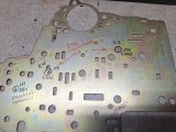
The circled feed holes are the ones that are typically modified as part of a shift kit modification.
The current hole sizes are .125 and .150 as shown.
The (.110) and (.120) are generally starting points for any size increase. As you can see the plate has been drilled out a bit more than that.
The orange .188 hole size is what the B&M directions indicate for street/strip.
I'm going to re-install this plate as-is because (1) the transmission is an unknown shift parameter at this time, all new clutches, seals, bushings.
(2) I don't know what impact the various modifications have added to the shift process'
(3) there will be a new higher-stall torque converter being used.
Speaking of the converter, after numerous inquiries to good reputation/quality companies I've moved forward to purchase of an ATI Streetmaster converter 408320 built to my particular engine/vehicle data. Although there's a series designation, these converters are built per your submitted info. This one is a 10 in converter with general stall of 2800-3000 rpm, the one I'm getting is on the tighter side.
I'll get an email when mine is ready.
 www.atiracing.com
This is the B&M separator plate that was in the unit, it's in good shape and I will re-use it.
Note - I had no issue at all with the shifting in this transmission, it was generally pretty good.

The circled feed holes are the ones that are typically modified as part of a shift kit modification.
The current hole sizes are .125 and .150 as shown.
The (.110) and (.120) are generally starting points for any size increase. As you can see the plate has been drilled out a bit more than that.
The orange .188 hole size is what the B&M directions indicate for street/strip.
I'm going to re-install this plate as-is because (1) the transmission is an unknown shift parameter at this time, all new clutches, seals, bushings.
(2) I don't know what impact the various modifications have added to the shift process'
(3) there will be a new higher-stall torque converter being used.
Speaking of the converter, after numerous inquiries to good reputation/quality companies I've moved forward to purchase of an ATI Streetmaster converter 408320 built to my particular engine/vehicle data. Although there's a series designation, these converters are built per your submitted info. This one is a 10 in converter with general stall of 2800-3000 rpm, the one I'm getting is on the tighter side.
I'll get an email when mine is ready.
ATI Streetmaster Torque Converters for Street and Strip use!
ATI custom built high performance torque converters for sreet use for GM, Chevrolet, Ford and Chrysler applications. Our converter customers have broken records and won numerous events and championships in NHRA, IHRA & NMCA drag racing! ATI builds torque converters using all new components...
Last edited:
Miscellaneous Parts ......
I started through the list of all the peripheral stuff that's still important....
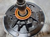
New sealing washers were installed on the pump bolts which were then torqued to 18 ft/lb.
I typically put a paint mark on final-torqued bolts for my old memory cells.
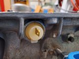
Next was installing the new case connector. This is the through-case connector for the wiring to the downshift solenoid.
After many years/heat cycles, there's no need to re-use the old connector.
Nothing complicated, a bit of blue lube on the o-ring and it just pops into place. There's a locating tab on the exterior side.
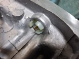
The speedometer assembly was installed next. I'm re-using the gear as it's in good shape and until I decide on final rim/tire size there's no need to mess with the speedometer setting. This is still old school cable connecting to the speedometer.
New o-ring.
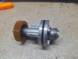
Here's the internal seal in the housing, has a small spring clip to keep it in place.
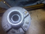
These are the old seals out of the speedometer gearset.
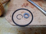
I left the tailshaft off until the speedometer and governor assemblies are installed.
Here's the speedometer gear meshing nicely with the tailshaft gearset. You can change one or both to different gearing.
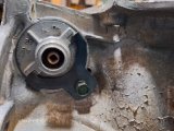
Retainer tab, bolt torque 60 in/lb
I started through the list of all the peripheral stuff that's still important....
New sealing washers were installed on the pump bolts which were then torqued to 18 ft/lb.
I typically put a paint mark on final-torqued bolts for my old memory cells.

Next was installing the new case connector. This is the through-case connector for the wiring to the downshift solenoid.
After many years/heat cycles, there's no need to re-use the old connector.
Nothing complicated, a bit of blue lube on the o-ring and it just pops into place. There's a locating tab on the exterior side.


The speedometer assembly was installed next. I'm re-using the gear as it's in good shape and until I decide on final rim/tire size there's no need to mess with the speedometer setting. This is still old school cable connecting to the speedometer.
New o-ring.

Here's the internal seal in the housing, has a small spring clip to keep it in place.

These are the old seals out of the speedometer gearset.

I left the tailshaft off until the speedometer and governor assemblies are installed.
Here's the speedometer gear meshing nicely with the tailshaft gearset. You can change one or both to different gearing.

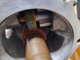
Retainer tab, bolt torque 60 in/lb

Miscellaneous Parts .....
Here's the components of the vacuum modulator.
Modulator, valve, retaining clip and bolt.
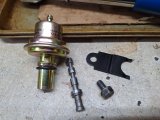
This is an adjustable modulator - turn the setscrew clockwise to raise the shift points and vice versa. However, that's a general overview - there's other factors that impact the shift points. These adjustable modulators can help with engines that produce slightly lower vacuum from larger cams or other modification. I'm using this modulator for some additional flexibility.
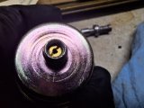
Interesting that the modulator valve had a flat in one of the lands - I looked up online images and this is normal.
Installed into the case. You can see the modulator can extends all the way to the valve body.
Correct orientation for the retention clip. Bolt torqued to 10 ft/lbs.
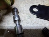
I started to install the governor assembly, but decided to replace the plastic end gear first.
ATSG includes inspection criteria for the internal valve clearance and the weight function.
In my case, the internal valve moved freely and was within spec, but I figured after 30+ years it would be a good idea to install a new plastic gear. Ordered a Sonnax replacement.
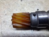
Last was to install the tailshaft housing.
I had prepped this awhile back with new bushing/seal, and I had also ensured that the driveshaft yoke slid into the bushing without issue.
Bolts torqued to 20-25 ft/lbs (I went with 22 ft/lbs). Gasket got a super-thin smear of Permatex #2.
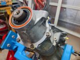
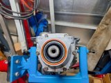
That blue fixture that I made was worth the effort - it's been so easy to work on the unit and it's sturdy as hell.
Note to myself that those are M10 bolt threads for the mount, lots of folks have mistakenly installed 3/8 bolts in there.
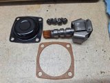
Here's the components of the vacuum modulator.
Modulator, valve, retaining clip and bolt.

This is an adjustable modulator - turn the setscrew clockwise to raise the shift points and vice versa. However, that's a general overview - there's other factors that impact the shift points. These adjustable modulators can help with engines that produce slightly lower vacuum from larger cams or other modification. I'm using this modulator for some additional flexibility.

Interesting that the modulator valve had a flat in one of the lands - I looked up online images and this is normal.

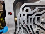
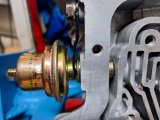
Installed into the case. You can see the modulator can extends all the way to the valve body.

Correct orientation for the retention clip. Bolt torqued to 10 ft/lbs.

I started to install the governor assembly, but decided to replace the plastic end gear first.

ATSG includes inspection criteria for the internal valve clearance and the weight function.
In my case, the internal valve moved freely and was within spec, but I figured after 30+ years it would be a good idea to install a new plastic gear. Ordered a Sonnax replacement.

Last was to install the tailshaft housing.
I had prepped this awhile back with new bushing/seal, and I had also ensured that the driveshaft yoke slid into the bushing without issue.
Bolts torqued to 20-25 ft/lbs (I went with 22 ft/lbs). Gasket got a super-thin smear of Permatex #2.

That blue fixture that I made was worth the effort - it's been so easy to work on the unit and it's sturdy as hell.
Note to myself that those are M10 bolt threads for the mount, lots of folks have mistakenly installed 3/8 bolts in there.

Last edited:
Governor ......
The new gear showed up so it was time to get it installed.
The job wasn't hard but it was somewhat fiddly. I didn't need the replacement pins, just the gear and roll pin.
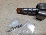
OEM roll pin is staked in place. No issue with using a drift to tap it out.
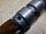
This made me glad I decided to replace the oem plastic gear. As I was pushing, prying a bit to get it out, it snapped. Sort of looked like it had been partially cracked for a while. It's a pretty tight fit in there.
I used a drill to carefully wallow out the remaining plastic.
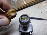
Here's the valve that's inside, in the correct orientation. The drift points to a small orifice that needs to be thoroughly clean.
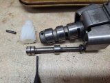
After some scotchbrite polishing and a good cleaning, the new gear was tapped into place and secured with the new roll pin.
The new pin was also staked into place. The entire assembly was checked for free and proper operation.
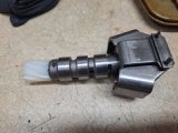
Note! when installing the new plastic gear, do not stand the assembly on a flat surface while tapping the new gear into place. You will bend the end plate which is designed to bear on the outer cover when everything is in place. If you bend the plate, it has to be completely removed to flatten out.
The new gear showed up so it was time to get it installed.
The job wasn't hard but it was somewhat fiddly. I didn't need the replacement pins, just the gear and roll pin.

OEM roll pin is staked in place. No issue with using a drift to tap it out.

This made me glad I decided to replace the oem plastic gear. As I was pushing, prying a bit to get it out, it snapped. Sort of looked like it had been partially cracked for a while. It's a pretty tight fit in there.
I used a drill to carefully wallow out the remaining plastic.

Here's the valve that's inside, in the correct orientation. The drift points to a small orifice that needs to be thoroughly clean.

After some scotchbrite polishing and a good cleaning, the new gear was tapped into place and secured with the new roll pin.
The new pin was also staked into place. The entire assembly was checked for free and proper operation.

Note! when installing the new plastic gear, do not stand the assembly on a flat surface while tapping the new gear into place. You will bend the end plate which is designed to bear on the outer cover when everything is in place. If you bend the plate, it has to be completely removed to flatten out.
Driveshaft ......
Technically not part of the transmission, but without it, that transmission won't do much good!
So I thought I'd include the refurbishment here too.
First built in July 2001. Very good service out of it.
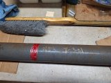
Straight, no dings, just needs clean and paint.
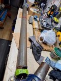
The u-joints were in overall decent shape, but still worth replacing at this point.
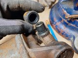
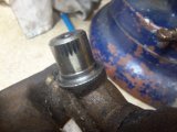
Removal was pretty straightforward - I just used my balljoint removal tool.
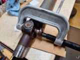
TH400 yoke of course. I'll clean it up.
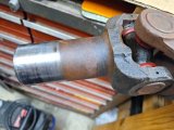
Front u-joint is a 3R series, 1.125" end caps, internal snap rings.
Replacement: Spicer 5-3147x (greasable) or 5-795x (non-greasable)
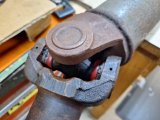
Rear u-joint is a hybrid, mates th400 yoke to Ford pinion.
It's a 1330 series, two caps 1.0625", two caps 1.125", external snap rings, straps at pinion.
Replacement: Spicer 5-1204x (greasable) or 5-7438x (non-greasable).
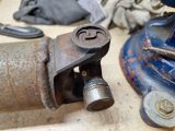
Comments:
- The car is equipped with a front driveshaft safety loop.
- I intend to use non-greasable u-joints. For the miles this car will see, I doubt I'll ever grease the u-joints, and non-greasable (non cross-drilled)
u-joints appear to be a bit stronger since they don't have a hollow core.
Website:
Dana/Spicer U-Joints
Technically not part of the transmission, but without it, that transmission won't do much good!
So I thought I'd include the refurbishment here too.
First built in July 2001. Very good service out of it.

Straight, no dings, just needs clean and paint.

The u-joints were in overall decent shape, but still worth replacing at this point.


Removal was pretty straightforward - I just used my balljoint removal tool.

TH400 yoke of course. I'll clean it up.

Front u-joint is a 3R series, 1.125" end caps, internal snap rings.
Replacement: Spicer 5-3147x (greasable) or 5-795x (non-greasable)

Rear u-joint is a hybrid, mates th400 yoke to Ford pinion.
It's a 1330 series, two caps 1.0625", two caps 1.125", external snap rings, straps at pinion.
Replacement: Spicer 5-1204x (greasable) or 5-7438x (non-greasable).

Comments:
- The car is equipped with a front driveshaft safety loop.
- I intend to use non-greasable u-joints. For the miles this car will see, I doubt I'll ever grease the u-joints, and non-greasable (non cross-drilled)
u-joints appear to be a bit stronger since they don't have a hollow core.
Website:
Dana/Spicer U-Joints
Last edited:
Valve Body Part 1 ......
This is separated into two parts due to the picture limit per post.
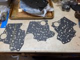
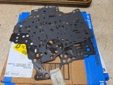
First thing is to verify that the correct gaskets are being used.
There's usually one case side gasket and two valve body side gaskets in the rebuild kit.
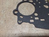
Case gasket usually identified with a "C"
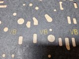
Valve body side was also marked, but I checked everything anyway.
Always keep your old parts until the project is completely done, you never know if you will need to verify something.
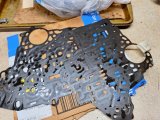
In this case, I simply matched the new VB gaskets to the old ones, making sure every hole in the gaskets and the separator plate was verified.
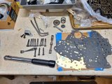
Here's the lineup of everything needed to install the VB.
I laid it all out to ensure that I didn't forget something.
This is separated into two parts due to the picture limit per post.
First thing is to verify that the correct gaskets are being used.
There's usually one case side gasket and two valve body side gaskets in the rebuild kit.

Case gasket usually identified with a "C"

Valve body side was also marked, but I checked everything anyway.

Always keep your old parts until the project is completely done, you never know if you will need to verify something.

In this case, I simply matched the new VB gaskets to the old ones, making sure every hole in the gaskets and the separator plate was verified.

Here's the lineup of everything needed to install the VB.
I laid it all out to ensure that I didn't forget something.

