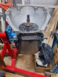
TH400 Amateur Build

Valve Body Part 2 .....

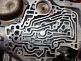
I installed 5 of the 6 checkballs, using online and ATSG as locating verification.
#1 checkball is omitted when the direct drum dual feed mod has been done - it's the one outlined in color.
1000004233.jpg

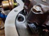
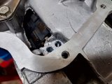
Governor tube screen installed into the case in the hole closest to the center of the unit.
Cone faces up into the governor tube.
1000004234.jpg

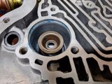
2-3 accumulator piston installed. Spring, then retainer.
1000004231.jpg

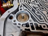
Followed by shaft, retaining clip and piston. Note that retaining clip goes into the bore before piston.
Piston with new teflon seal was eased into the bore, flat side up.
1000004232.jpg

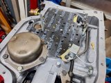
Getting the VB aligned with governor tubes, gaskets, and shift pin was fiddly enough that I made a couple of alignment pins (recommended in the ATSG manual) to help keep everything lined up. This was very helpful.
Note that the downshift solenoid is loosely installed at this point.
1000004237.heic.jpg

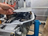
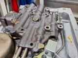
Valve body installed over the alignment pins. You're adjusting the VB and governor tubes at the same time as you do this.
The VB won't sit flush due to the 2-3 accumulator spring - as you tighten the VB bolts you can push it down slightly to ensure full alignment.
You want to wiggle everything slightly to be sure that all bolts insert easily through the gaskets/separator plate.
1000004238.heic.jpg

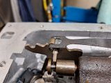
Verify that the shift pawl pin is correctly engaged into the manual valve, and that the retaining bolt has the spring clip.
The valve should move freely throughout the shift range.
1000004240.heic.jpg

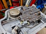
Valve body installed and torqued to 98 in/lb.
I typically use a torque wrench on every critical installation with paint mark on the bolt head to indicate "done".
1000004239.heic.jpg

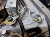
Detent (downshift) solenoid bolts torqued to 89 in/lbs and wire connected to the new case connector.
That's a new detent solenoid too. Note - pay attention to the wire routing, keep it away from the shift rod movement.
1000004241.heic.jpg

New dipstick tube seal installed.
1000004242.heic.jpg
 
Last edited:
Governor ......

In a previous post I had replaced the plastic gear, now time to install.

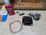
Here's the bits and pieces needed.
1000004298.jpg

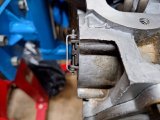
Governor fully installed/engaged into the output shaft gear.
Note that flat piece on the end - it uses the cover plate as support when operating, sort of a thrust washer scenario.
Another reason you don't put the assembly on a flat surface while hammering the new gear on - you will bend that plate. If the plate gets badly bent then it has to be removed to be flattened out.
You can see it has a slight bend from normal use. I left it as-is since there wasn't an issue before.
1000004299.heic.jpg

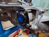
Cover plate in place, bolts torqued to 10 ft/lbs. The gasket was coated so I didn't use any sealer.
Because there's a lot of changes in the transmission, I may need to go back and do some adjustment on the shift points.
1000004300.heic.jpg
 
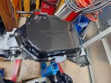
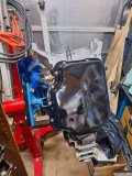
Pan .....

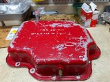
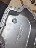
Not sure why the heck I had painted it red lol. Anyway, time for a good cleaning.
I intend to replace it with a good thick aluminum deep pan, but I want to see how the transmission works first. I don't want to spend $125 on a pan if I have to go back into the unit. The steel pan that's on it is a GM deep pan so at least there's some heft to the thickness.

My plan - after successful initial operation - is to drop the pan, replace whatever fluid drains out, replace the fiber filter with a screen filter and install a new aluminum pan.

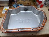
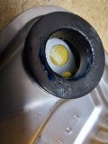
Current status. That's a temperature gauge sensor as a drain plug. I'll clean up that welding too.
1000004302.heic.jpg

No more rtv in the future, and I have a new round magnet for it.
1000004301.heic.jpg

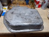
Oven cleaner has been my favorite paint remover for years.
1000004304.heic.jpg

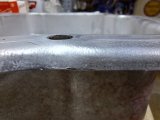
And I'll go over the rail to ensure it's all flat.
1000004305.jpg
 
U-Joints ......

I'm still cleaning up the driveshaft, but before I get into the final installation, I think this series of tutorials is outstanding.
Yes, I know we've all used the hammer and socket method, but it's worth looking at the tech aspects. I learned quite a bit.
This isn't every tutorial, just the ones that I used.

Weber State University - Automotive Training

Introduction and Tech


U-Joint Comparison

U-Joint Removal

U-Joint Installation

U-Joint Centering & Adjusting Axial Play
 
ATI Converter....

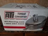
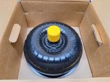
Arrived today in good shape.
1000004332.heic.jpg
1000004331.heic.jpg

10 in converter series 2800-3000 stall. This one built on the tight side per my specs.
1000004333.jpg

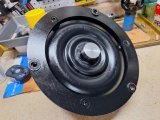
I like the heavy ring for attachment and machined hub.
1000004334.heic.jpg

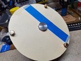
I'll check everything of course. Made a template to check flexplate bolt pattern and to ensure hub fit into crankshaft. I'll also fit the converter into the pump. 1000004335.heic.jpg
 
U-Joints ....

Just a couple things today.
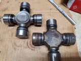
Front u-joint uses internal c-clips. Here's side by side of new and old u-joint.
1000004341.jpg

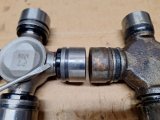
Interesting that there's an internal thrust washer/bearing inside the cup. You can the screwdriver pointing to exposed trunion - this is the uncompressed internal thrust washer not allowing the cap to fully seat. After installation the cap will seat.
1000004342.jpg

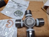
Rear u-joint that uses external snap rings. Spicer includes a couple different thicknesses depending on final installation.1000004343.jpg
 
Never ever got different sizes snap rings when i bought u.joints? What is the PN?
Check on post 139 for some more details, but I'm using Spicer:
5-795x front
5-7438x rear

But remember to consider what your particular requirements are for sizing.
 
Converter and Cooler Lines .......

Things are starting to get closer to transmission installation, so there's going to be a little broader approach getting different things done.
Rainy today so the pan and driveshaft are still in primer.

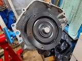
I did test fit the converter and flexplate though. Very nice smooth fit and I made sure it was fully seated, has to mesh with the input shaft, the pump stator, and the pump gears. Solid clunk when it's in place but I also made some measurement checks and the bolt circle at the flexplate.
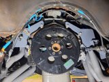
The flexplate has a dual pattern - this converter uses the 10.75 in bolt circle.
1000004347.heic.jpg

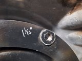
When seated, the face of the converter attachment lugs are 1 1/16 " inset from the bellhousing flange surface.1000004348.heic.jpg

The face of the flexplate mounting pads are 7/8" away from the face of the rear engine block. The pads face away from the engine.

According to the ATI installation directions, there needs to be 1/8" to 3/16" clearance from the converter lugs to the flexplate pads when the converter is fully seated. Meaning that there is room for the converter to pull out from the pump. So it looks like I'm at 3/16", should be ok.

Next, I looked at cooler line routing. The old lines can't really be totally duplicated due to the revised mid-mounts that I had made.
The lower part of the mount - by the starter - blocks the lines from routing close to the block and behind the starter, then to the transmission.
1000004350.heic.jpg

This isn't a surprise; I knew this when I re-designed the mounts. Routing new lines is the most flexible aspect of mounts vs. lines.

The cooler has 6AN fittings, and I'm installing new 6AN/1/4NPS fittings at the transmission. Note that in this unit, these are not NPT fittings, they are straight thread. I can use (1) ni-cop tubing with braided PTFE hose at each end or (2) braided PTFE hose for the entire line.
I'm just thinking about appearance and routing right now to make a decision. I'll probably route along frame rail and not against the engine block along the oil pan.

Incidentally, those mid-mounts bolt to the transmission, so the engine has to be supported while the transmission is being installed. Nothing new on this, I've always used this mounting arrangement, just made much stronger mounts this time. In the picture above, there's spacers between the mount and the engine that mimic the thickness of the transmission bellhousing flange. This ensures that the mounts are properly located front to back.
 
Did you consider running the lines inside the frame?
.
Yes, I'm considering that, but it's a factory boxed frame. So access is more limited.
Actually the transmission can be installed without issue to the cooler line routing. Makes install time-line a bit smoother.
I've got my thinking cap on!
 
Could you drill your own hole and maybe us bulk head fittings.To be able to get to the fittings inside the frame would require a rather large hole. Probably the hole would need to have a plate screwed to the frame to cover the hole since it would be large.

It would be considerably more work for a little bit of clean up, mostly cosmetic.
 
I'm reluctant to drill the diameter holes need for bulkhead fitting or even grommeted access for the lines. I think 2 black braided lines clipped at the frame, routed neatly will probably be ok. Or 2 ni-cop routed same with braided ends.
Using 2 braided lines gets rid of 2 possible leak points too.
I'm spending time just looking in the engine compartment and under the car thinking about different routings and options. To others it may look like goofing off lol, but I know you guys have done the same!
 
Dipstick Tube .....

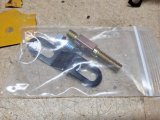
I saw decent reviews on this dipstick tube assembly, decided to give it a try. The old tube was one of those chrome things, rusting.
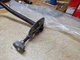
The top of the dipstick is one of those folding type handles that helps to lock the dipstick in place.
Quick summary - I think it's a pretty good item.
1000004378.heic.jpg

Includes some additional brackets and widgets. I'll verify best attachment after the transmission is in place.
1000004383.jpg

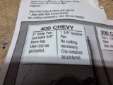
Followed the instructions for a TH400 with deep pan.
1000004379.jpg

1000004380.heic.jpg

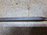
The dipstick is marked well.
1000004381.jpg

With tube installed, the full level mark is right where it needs to be, just shy of the pan gasket.
1000004382.jpg

Cooler Line Fittings .....

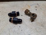
The case fittings are 6AN to 1/4 NPS (straight pipe thread NOT npt). New aluminum fittings next to the original brass fittings.
Note the copper compression washers on the new fittings, the original fittings had fiber faced washers.
1000004376.heic.jpg

There's a couple different types of these fittings, some have copper washers, some have rubber o-rings. I chose the copper washer version - I think that for the long term the copper washers will seal dependably vs a rubber o-ring that will eventually deteriorate.
I used a light coat of Permatex #2 on the threads and a very light smear on the washers, should be fine. The picture sort of makes it look like there's two different size fittings, but they are both the same.
1000004377.jpg


Rear Mount ......

I'm going to replace the rear mount, but for some reason I'm having a bit of fuss finding the identical mount. There's a couple of mounts that are almost the same - I think they will work, but for now I'll use the old mount. It's in decent shape, good enough to get the car driving, and it's easy to change it anytime.
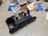
It's upside down here, the wider spaced holes are for the M10 tailshaft bolts, these are 7/16-14 bolts that go through the crossmember.
1000004384.heic.jpg

Not shown, but I spent time getting some chain supports attached to the rear of the engine so it can be held securely while the rear mounts are removed for the transmission install. Plus some general looking and thinking about the installation sequence, bolts needed, etc. I also verified that the best cooler line installation will be 6AN hoses from the unit to the cooler, no hard lines, plus I now have a good idea of the routing/attachment.
 
thank you for posting the added info and pictures as they help a good deal:like:
 
Transmission Finished........

Finally lol.

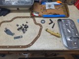
Parts for the pan installation, except that rubber elbow. That's for the vacuum cannister.
20240319_145221.heic.jpg

New magnet, goes around the indent in the pan.
20240319_150631.heic.jpg

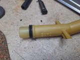
Double o-rings at the filter (suction) tube.
20240319_145143.heic.jpg

Here's the deep pan version of the filter installation. The longer suction tune and longer filter bolt with spacer get the filter right to the bottom of the pan. Note - there's no inlets on the bottom of the filter, only on the top side.
20240319_150054.heic.jpg

There's two filter versions - fiber and screen. I was thinking this was a fiber filter but it looks like a screen filter. The screen filter is preferred for performance builds as it flows more fluid, but I was ok with initial break-in with a fiber filter. Anyway, it's got the screen filter and I'll change it out a bit later as the unit gets some miles on it.
20240319_145741.jpg

Pan installed, bolts torqued to 98 in/lbs. I put a light smear of Permatex #2 on the pan side of the gasket, nothing on the case side.
That's the shift linkage bracket on the side - I'm using a B&M Z-Gate shifter.
20240319_153653.heic.jpg

And done......now we'll see if it actually works!
20240319_153726.heic.jpg

20240319_153749.heic.jpg
 
Back
Top