NOT A TA
reliable source of info
Thanks Rick! I read a lot of the engine stuff Grumpy covers to learn more. I've spent a lot of time working in a machine shop the past few years and found that the more I learn about engines I realize how much more there is I don't know. Went through a whole discussion there today figuring out what's needed on a Saturn V6 head job a family member called me about. Learned the engine's a 3.0 DOHC made by...... OPEL!
The early 2nd gen Trans Ams had cool looking front air dam fender flares from the factory. Most got smashed eventually on tall curbs, steep driveways and other road hazards so they usually need some repair and both of my front wheel flares were cracked in the usual locations. They were cracked when I got them 20+ years ago and I used some type of epoxy to "fix" them as well as I could with what was available to me at the time. They lasted probably 10 or so years before the cracks reappeared. Now we have other methods available so here's my 21st century repair.
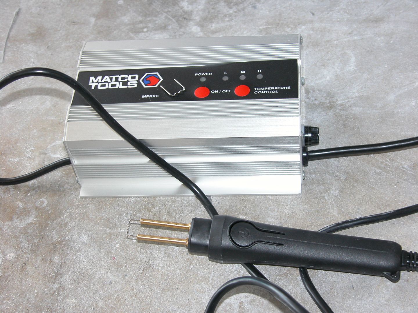
Sanded the flares down to plastic. Hot stapled the cracked areas. Clipped staples off and ground down the stubs below finish level. Applied adhesion promoter and then 3M hard plastic repair material and let cure 24 hours. Sand plastic repair material and prime, fill nicks, then sand/prime till ready for sealer.


The early 2nd gen Trans Ams had cool looking front air dam fender flares from the factory. Most got smashed eventually on tall curbs, steep driveways and other road hazards so they usually need some repair and both of my front wheel flares were cracked in the usual locations. They were cracked when I got them 20+ years ago and I used some type of epoxy to "fix" them as well as I could with what was available to me at the time. They lasted probably 10 or so years before the cracks reappeared. Now we have other methods available so here's my 21st century repair.
Sanded the flares down to plastic. Hot stapled the cracked areas. Clipped staples off and ground down the stubs below finish level. Applied adhesion promoter and then 3M hard plastic repair material and let cure 24 hours. Sand plastic repair material and prime, fill nicks, then sand/prime till ready for sealer.