"The 14 Car" Performance therapy project

NOT A TA said:
My sidepipes will hit way before the frame connectors. Only clearance issues I've really had on 2nd gens was with slapper bars hitting speed bumps. I took this car to the strip a bunch of times, well over 100 passes on it at Lebanon Valley, Bradenton, Silver Dollar, the old Moroso and the new PBIR. Started running 16.4 with the original 350 2V and got down to 13.9's with the 400. Will go again with the new exhaust, carb etc. and see if I can get it into the low 13's. I've had quicker cars but it's fun to take it once in a while anyway.
You Really Have a Dedicated Road Racer.
Hellcats & SRT Vipers look out.
Lots of stroker kits for Pontiac V8's.
$ Always a factor.
Using your 400 & and A stroker crank. Build a 455.
 
Unfortunately my 400 is one of the later weaker blocks. If I can afford it I'll get an IA II block and build a big cube stroker when the time comes. The car is more of a high speed road track car overall but I'd like it to be able to get down into the 11's when it's finished.
 
I am keeping an eye out for all Pontiac near me.
Buy when I can.
Let you know what I find and bring homr.
I like trading.
 
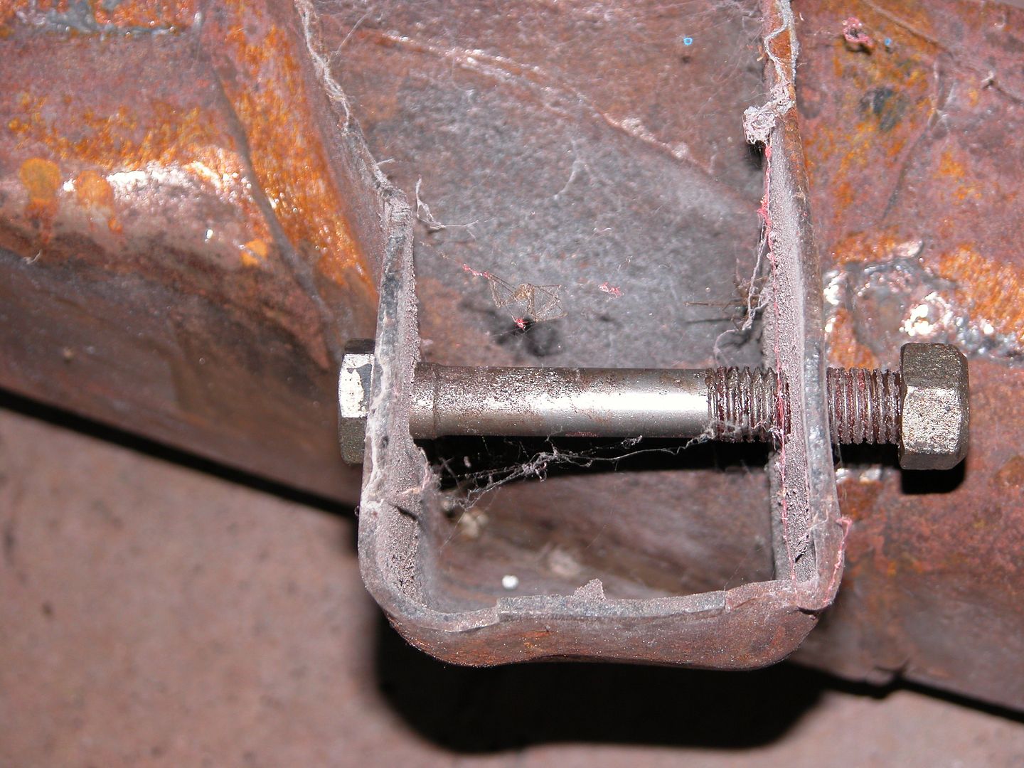
The lower control arm mounting points holes in the 1st and 2nd gen frames are often worn or damaged. The design really isn't very good IMO. Forces from cornering, bumping parking blocks, hitting potholes, etc. is transferred to the frame through the LCA bolts to the edges of the holes in the sheet metal the frame is stamped out of. Thats not much surface area and making it worse the bolts are shouldered on one side but the other side of each bolt just has the tips of the threads hitting the frame. Since the bolts are hardened steel they deform the holes in the softer metal of the frame ovalizing them. I see it a lot on 2nd gens and since the 1st gens did the same thing I'm surprised the engineers at GM didn't come up with something better for 2nd gens.

Now some of us put stiffer springs, tubular control arms, solid bushings, wider modern sticky tires, and big fat sway bars on the car and then take the car out for spirited driving, auto-X, and even road track use. The force on the thin sheet metal bolt holes in the frame far exceeds what the engineers had in mind. Heck, radial tires weren't even standard on most American cars yet when the suspension was originally designed.

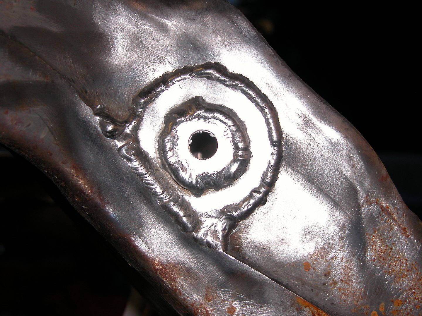
If the LCA mounting holes are ovalized (or you want to reinforce them) a piece of thick steel with a hole drilled in it or a thick washer(s) can be welded to the frame. Welding something to the frame should also reduce flexing theoretically allowing our cool new suspension & tires to perform their best. When possible, I like to use a long piece of all thread rod with nuts through the frame to line up the holes of the washers or metal being welded and hold them tight to the frame to tack weld in place. Then remove the rod and fully weld. If a rod won't slide through all 4 holes on one side because of crossmember interference I'll bolt the control arm in place with the pieces to be welded, tack in place, remove arm and then fully weld.

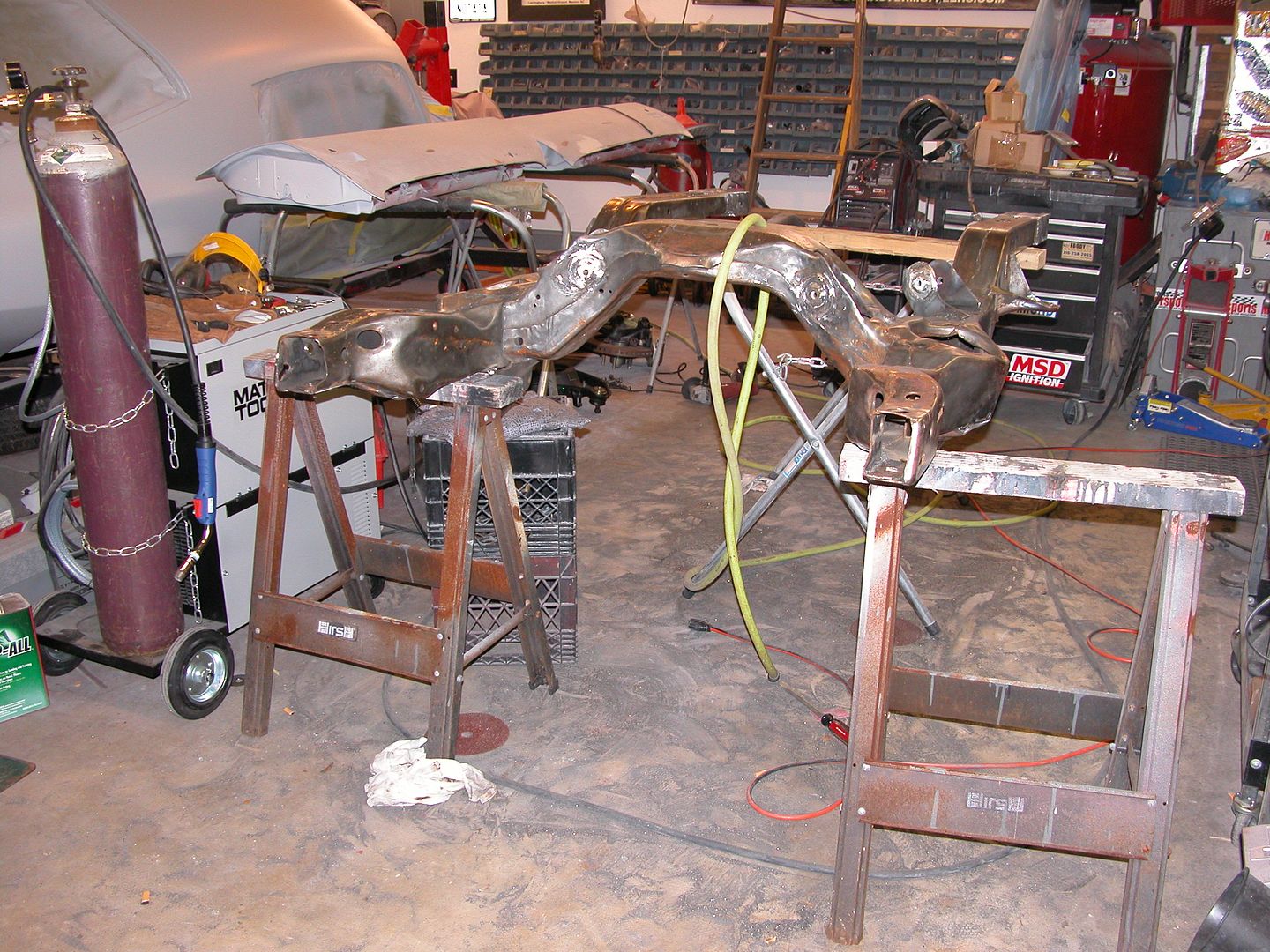
On the frame I'm currently preparing (81 subframe into a 70) I wanted to strengthen the frame, reduce flex, and reduce wear as much as possible within my budget. To complicate things I want to use my old control arms with the 1/2" bolts in a frame made for the larger diameter metric bolts.

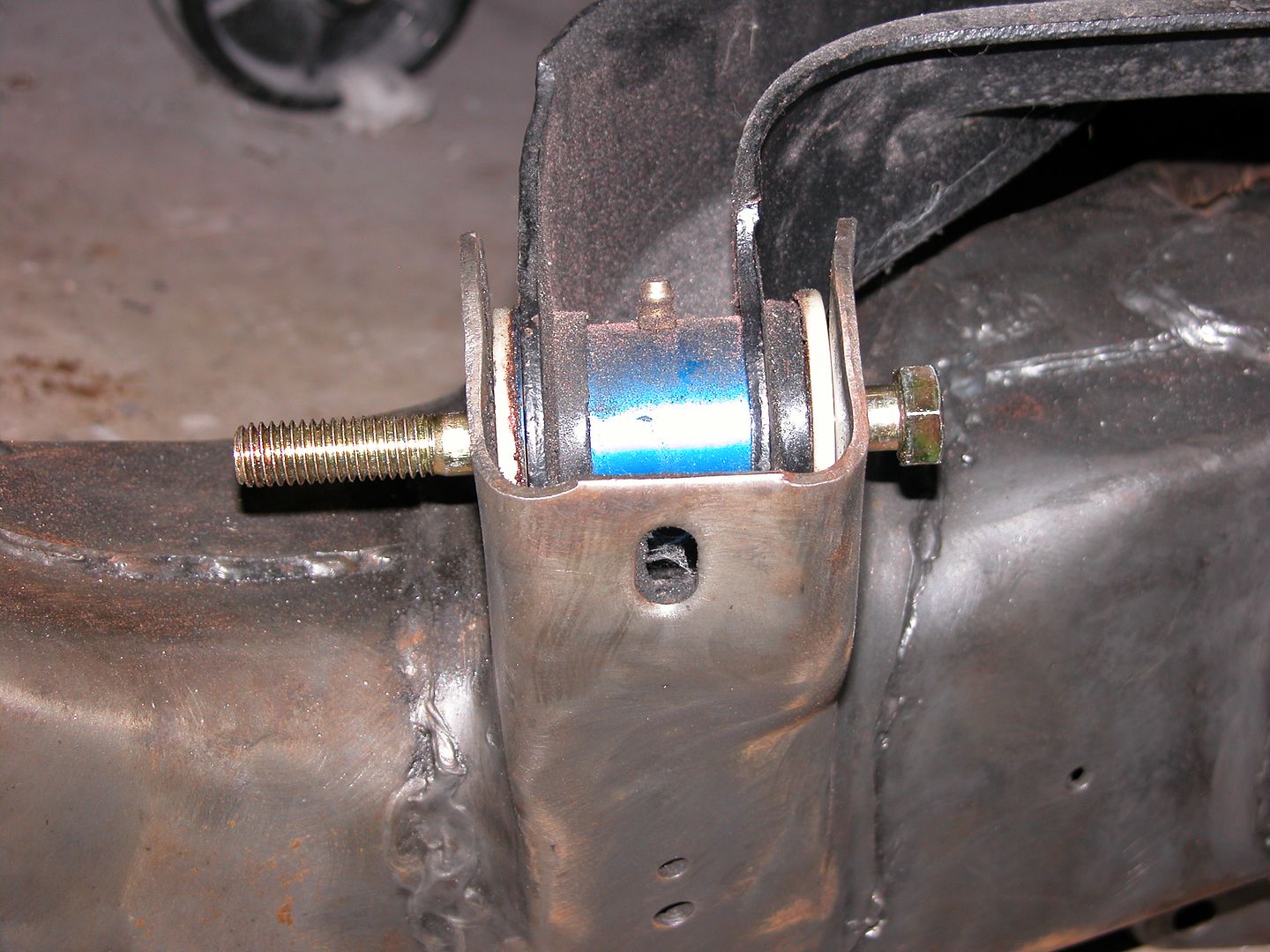
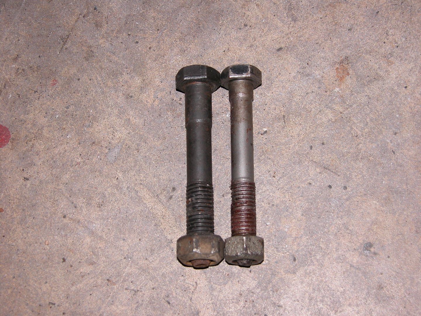
Here's the 2 different bolts I'm aware of, Metric 81 on the left and 1/2" on the right. In the next pic note the shoulder where the frame sits on one side while the other side is on the bolt threads. Really GM? Couldn't think of a better way after seeing it didn't work well for the 1st gens?


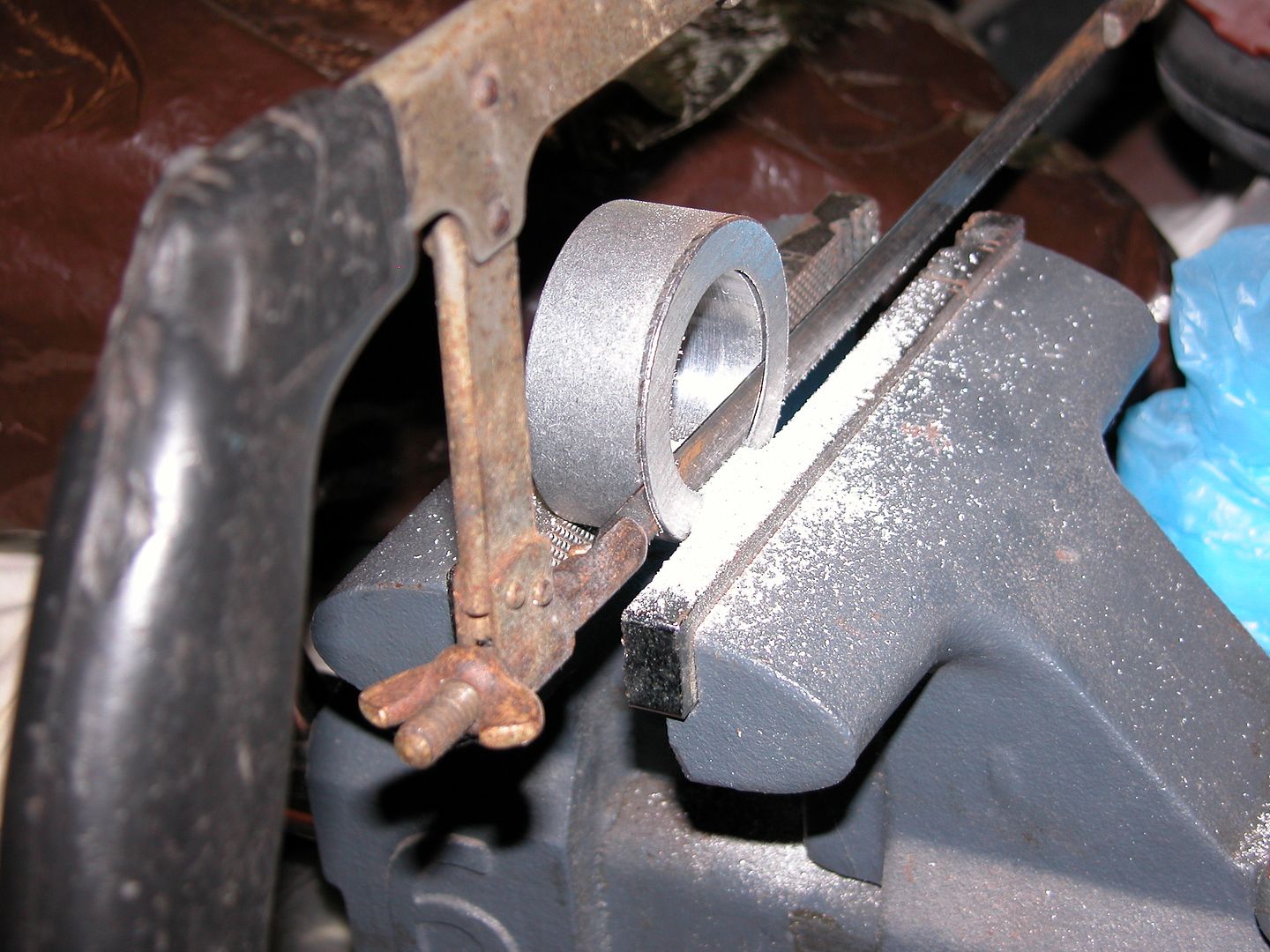
So here's my plan for the current project where the LCA attaches. This will reduce the holes to 1/2", stiffen the area, and hopefully prevent ovalizing.

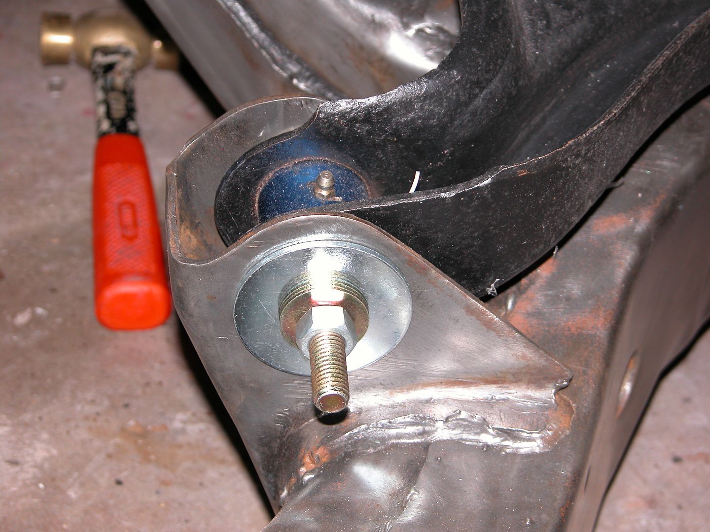
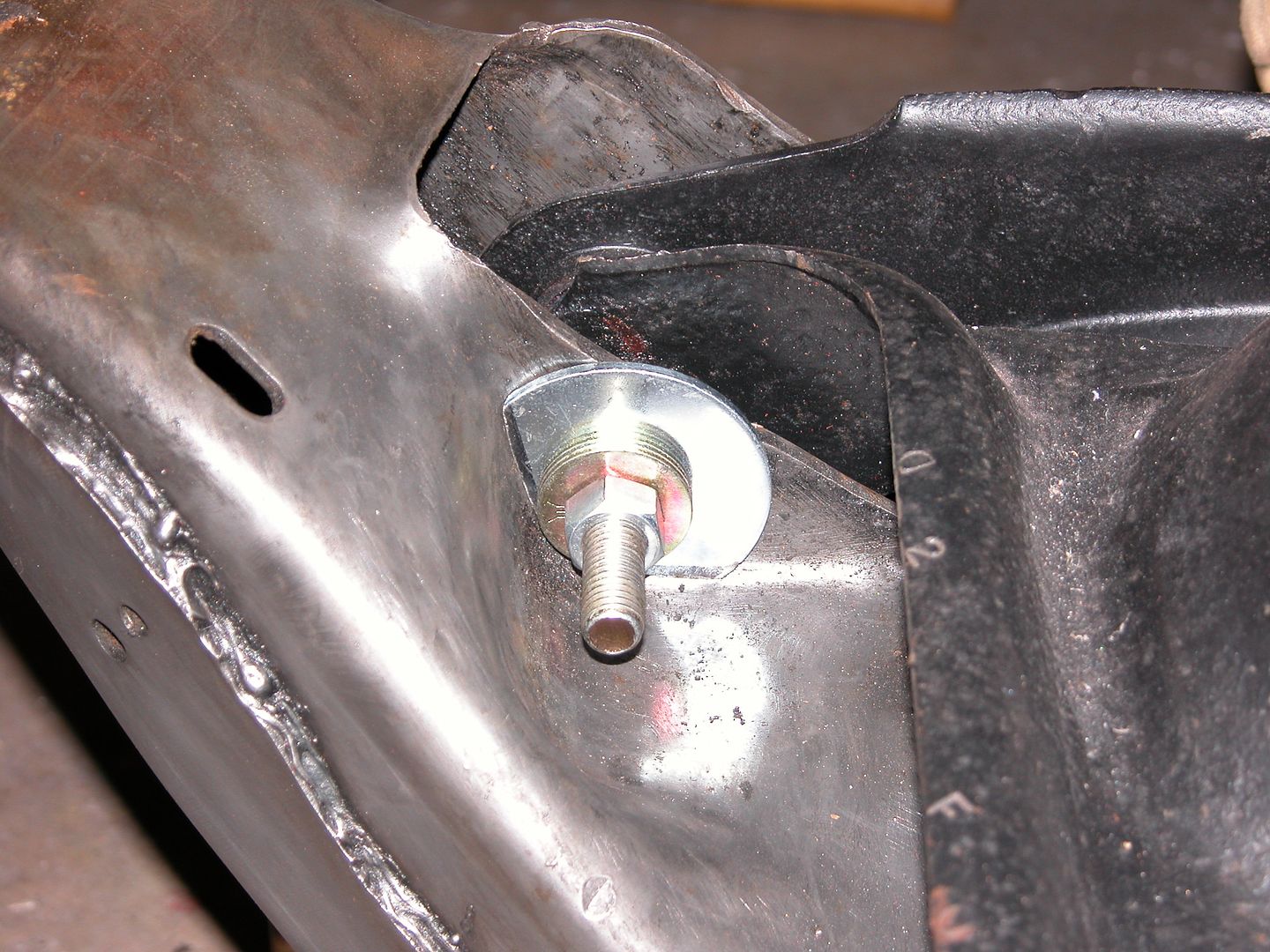
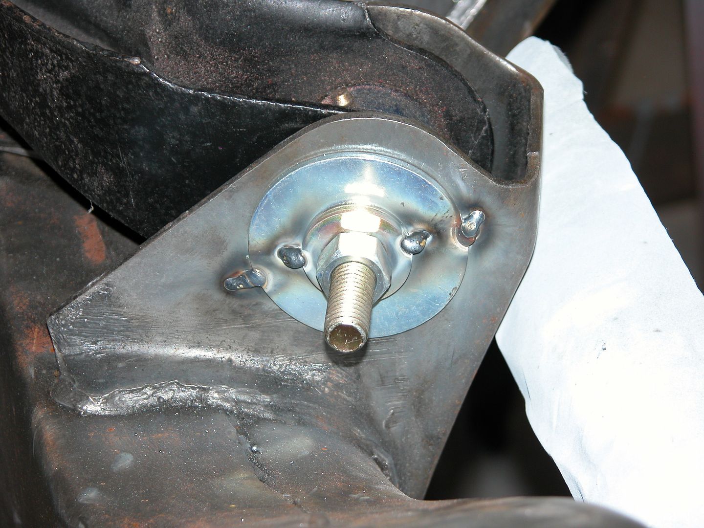
1. 1/2" ID 2 1/2" OD body washers 1/8" thick to stiffen the frame. Some are cut and bent to fit and welded into place.

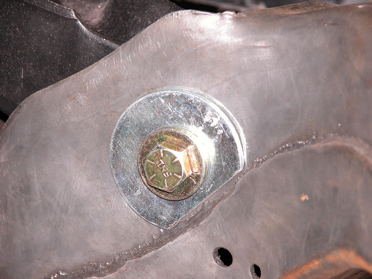
2. 1/2" grade 8 bolts with a shank section about 3 3/8". The long shank section will keep the threaded part from transferring the shear forces to the edge of the frame sheet metal. New tapered thread locknuts will be used for final assembly, regular nuts for mock up etc. are seen in the pics below. Keep in mind kids those factory tapered thread locknuts are considered single use fasteners and should be replaced if removed.

3. 1/2" grade 8 washers welded to each other and welded to the big washers will take the forces that originally went to the edge of the frame sheet metal. This will spread out the force because the combined thickness of the washers is greater than the frame sheet metal. Also, because of the longer shank section both sides will have full contact rather than one side putting the force on the thread tips. With the large washers and 3 of the grade 8's on each side the nuts won't bottom on the shank when tightened. Grade 8 washers are being used because they are made to closer tolerances than cheap washers and fit the bolt shank tighter. I'm aware they'll lose their heat treating when welded.

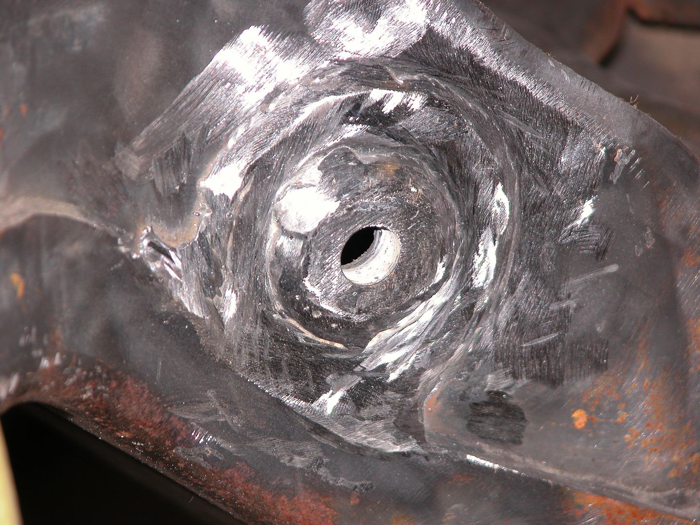
Since I'm switching from the metric size frame holes to the smaller 1/2" holes there's a slight movement before everything is welded. I'll pull the LCA So any slight change in position will give me a little extra positive castor. I'll do some more weld grinding and polishing before sandblasting so the frame is pretty for body color paint. Next post is upper control arm/shock mount modification.


When you install the engine mount to the frame, please can you post pictures?
I know they are not easy(nuts inside the frame/control arm opening), but you have the control arm out ofthe way, am just curious since i will probably be changing my this summer.
 
Upper control arm/shock brackets got trimmed where the bracket hangs over the outside of the frame rail then bent to the rail and welded across between the factory welds. The increased stiffness ar added strength advantage is probably debatable but in theory it should be a bit more durable, removes a little weight, and looks cleaner (although you can't see it under stock upper arms).


The donor 81 bird had taken a punch in the nose at some point in time that had stretched the slotted bumper bracket holes in the subframe. I put a hydraulic cylinder in the frame and massaged the metal back into place with a BFH. In the first pic you can see the piston in the frame for support behind the hole on the right thats been straightened quite a bit already. Without the support inside the frame the area around the stretched area would cave in if I just started smacking it in with a hammer, it would work, but the bumper brackets might be harder to adjust later.


With the frame ready for mock up and the unibody (except splash pan) in the final coat of PPG K38 primer it was time to get the body off the rotisserie and onto some wood cribs. Then I spun the body around to roll the subframe into place, took some measurements, and then set it straight with the body before snugging up the body mount bolts. Next I started hanging suspension parts so I'll have enough weight on the front to get the rear suspension, axle, and wheels installed so that I can use wheel cribs and go-jacks under it. The rotisserie lifts cars much better than lowering them so it's easier for me to just use my jack cribs to get it off. I made some special cribs to fit on top of the go jacks so that I can use the wheel cribs on the go jacks which roll soooo nice. With the car being as stiff as it is because of the cage I've found it's more stable to have the car on 3 stacks when it's not fully loaded with weight especially if I'm going to roll it around. Once it's where I want I take out the go jacks and put it on 4 stacks of cribs.


Mathieu I'll have a post just about the engine frame mounts because the frame I'm using isn't drilled for the old style motor mounts I have. I have a couple tricks you'll like.

After test fitting the subframe to make sure the body mounts lined up properly I cut down the body mounts for the rear of the subframe to make up for the metal I added boxing the frame where the rear body mounts are. The thickness of the metal boxing the frame isn't really thick but this will keep the subframe from tipping up and raising the radiator support.


Once the cut down body mounts were in place I laid out the chassis/suspension components and started mocking up all the components. The plan is to assemble most of the suspension and front end sheetmetal. Then once everything is in place the doors and front end sheetmetal can be aligned and blocked sanded before final primer. Then everything will be taken apart so the subframe and most of the components can be painted. First time it's been back on 4 wheels in a few years!


love the detailed pictures, it shows what your doing better than a description probably would!
and I'm sure it illustrates the high quality and thought that went into that work better, many guys don,t bother to think things through!
 
Last edited:
love the detailed pictures, it shows what your doing better than a description probably would!

Thanks Grumpy, the new format threw me for a loop because the edit feature for posts shows the actual photos instead of the link address. Makes it harder to write a post for a thread with lots of pics.
 
While cleaning and prepping the rear swaybar for install I remembered I wanted to post about reuse of locking fasteners.

Lock washers, nylock nuts, tapered thread nuts, and other locking fasteners work best the first time they're used and in many cases are considered single use fasteners. I see far too many instances where people building/rebuilding cars remove and reinstall these types of fasteners over and over to the point the fastener has no locking effect before the car ever hits the road. Then when the car starts being used various things start loosening up.

For a rebuild like this one I lay out all the parts. Then I take one of each locking fastener and tag it as to where it goes and how many I need, go to Fastenal, hardware store, Home Depot or wherever and buy all new fasteners. When I get them, I bag and tag them to be used during final install. It's cheap insurance that I won't be sidelined in the middle of an event or stranded roadside. I don't replace all the hardware, only the locking pieces.

In the last pic you can see there's two nylock nuts on the bottom of the shock absorber. I run two different rear ends, one for drags and one for high speed. I'd swapped the rear a couple times and removed the shocks for clearance (reusing the nylock nut) and then during a track session at Road Atlanta I heard a clunking in the rear. So I got off track and pitted only to discover the nylock nut had backed off. Simple fix once I found another nut and just double nutted it, however it cost me most of a track session so probably a couple hundred bucks in track time when all the expenses of a track day are considered. Been double nutted since but getting new nylock nuts for the bottoms of the shocks now.

When I installed the Hotchkis suspension the first time (long ago) I reused the tapered thread nuts that hold the upper control arms to the frame mounts. Took the car to a shop for alignment then took the car on vacation from CT to FL. When I got to FL I heard a clunk in the front end entering a parking lot. Not only had a nut backed off but the alignment shims were gone! Yay! Got to pay for another alignment. So, learn from my mistakes and don't reuse locking fasteners.


With the subframe and suspension in place so the car could sit on four wheels it was time to start fitting sheet metal. Trunk lid was first up and with some tweaking the new (used) lid lines up nicely. So I moved on to the front end where my first task was to figure out if the 81 subframe would work with the 70 core support.

The later frame mounting holes for the core support are farther apart than on the early frame and the directions for the PTFB solid body mounts say they can't be used with the 70-73 Firebird core supports. BUT, I paid for the solid mounts and I'm using them! I marked and opened up the body mount holes in the subframe to fit the sleeves that come with the PTFB solid mounts. While opening up the holes for the solid mounts I found that the bushings wouldn't sit flat inside the frame rail because of the way the frame is made (like the rear most body mounts) so I welded in some sheet metal pieces I made.


Next used my tram gauge to measure and mark the core support for the new body mount location and larger diameter. Then opened up the holes in the core support for the mounts. I made the holes slightly bigger than necessary to allow a bit of side to side and fore/aft adjustment of the core support.

I had poly body mounts previously I installed back in the 90's. At the time I used a 1/2" thickness bushing between the frame and core support as instructed. I always had a lot of shim stacks to get good fender/bumper/hood gaps and so I'm test fitting the body panels with the thick 1" bushing between the frame and core support to see if things fit well with them (if not I'll switch to the 1/2" and test fit again). If the 1" bushing doesn't work out I'll come back and modify this post.


Looking Great '70 Bird Man. !

Thanks! It's gonna kill me to take it all back apart for setting up engine/trans mounts and paint. ahahaha.

After deciding the solid mounts can and will be used for the core support I enlisted my buddy Jeff who's helping me with the exterior bodywork to give me a hand installing the fenders etc. and starting to line things up so we can do blocking on the doors, hood, and fenders before the final coat of primer.


With sheetmetal roughly in place and waiting on some new bolts for the bumper I mounted the tall rear spoiler I'd roughed in a while back so I could sand it in place on the car and get the pieces uniform and contoured nicely.

In the top pic pic (before being installed for sanding) you can see where the fiberglass was added and about how much taller this spoiler will be compared with the original. The idea being to make it fatter than it needs to be, then sand till it looks right to me, then a skim coat of filler and block sand till straight/smooth, then prime/block/prime. I'll also be mounting up my old rear spoiler for the same procedure and will keep it the stock size so I have my choice of regular spoiler or spoiler on steroids for track use. Last pic shows a guide I made to get the spoiler height uniform and curved like the decklid, sticky sandpaper is used on the plywood part.


The rear spoiler is a focal point on a lot of 2nd gen F bodies and very easy to see. Since they're 35-45 years old now most have deformed or been damaged over time. The plastic slowly drying out and shrinking causes them to become wavy and crack. Some are worse than others of course and I'm lucky the two I'm working with were in pretty good condition to start with.
The tall one I'm making was from a 76 and needed some stripped threads repaired and missing studs replaced so I welded some small washers on 1/4" X 20 threaded rod and made several replacement studs (since I couldn't buy any locally). While I was making them I made the threaded part that screws into the spoiler a little bit longer to grab virgin threads at the bottom of the holes. Several drops of fiberglass resin in the holes before installing the new studs carefully and problem solved.
Next issue with spoilers is getting them to line up as well as we'd like. Often we're dealing with used or aftermarket quarters, deck lids, tail panels etc. which may not be the same as original. Our standards for panel alignment and gaps has raised quite a bit over the years since these cars were new and even when new the alignment/gaps weren't all that great from the factory. Here's my way of bringing old rear spoilers back to usable condition with better fitment and gaps than stock. I'm sure others have different ways of accomplishing the same goal and there's more than one right way to do things.
Strip the spoiler with 80 grit and clean old paint, sealers etc off the inside of the spoiler around the mounts and pads it sits on where it meets the body. Then install center section on trunk lid (trunk lid aligned previously). Clean old paint, sealers etc off the inside of the spoiler where it meets the body. If the mounts on the inside of the spoiler have to be modified by grinding a little off so the spoiler sits nice, so be it. Also, the holes in the decklid may need to be ovalized a bit to get the center section where you want it. Once happy with the center section, snug up the nuts on the ends to hold it in place. Then install end caps and see if you can get them lined up pretty well with the center section with the nuts snug. Again, may need to slot holes or modify the inside of the spoiler cap so it sits nice on the fender. Be patient, take your time and shuffle the pieces a little one way or another to get the pieces to sit as nice as possible on the sheetmetal and have the best gaps. If necessary move the center section a little and try again, when satisfied tighten the nuts. Then...
The ends of the caps and center section have often been sanded for previous repaints and the plastic has shrunk and deformed so after 35-45 years they're usually not very flat anyway. Apply a coat of your favorite body filler over the gaps between the end caps and the center section, don't try to fill the entire void, just bridge the gap. Ya, I know, it just seems wrong. Then use a hacksaw to cut a slot centered where you'd like the center of the finished body gap between the center section and end caps to be. Next use a thin file like a saw and cut the gap wider. Then use thicker and thicker files to widen the gap till it looks the way you want. Using the files keeps the slot straight and even because they don't flex much. If you want to move the gap a bit one way or another just apply pressure to the file as you're cutting with it. Once you've got the gap where you like it open the trunk and apply filler to the voids on the ends where the filler used to bridge the gap didn't go. Then close trunk and use the file again, repeat as needed till the ends just have little voids and pinholes in the bondo.


Because the spoiler plastic has shrunk, warped etc. over the years They're not straight anymore. At a minimum they'll need high build primer and block sanding. I'd hoped that would be all I needed to do for the one below but as you can see after some blocking on the one in the pic below I've already cut through the primer to the plastic and haven't even removed the guide coat in the low areas where the mounts hold the spoiler to the car. This was on a spoiler that spent 99% of the last 25 years in a garage since I did the car the first time. I've seen the same pattern before and apparently the mounts pull enough so the spoilers deform as the plastic gets old. The cure is to skim coat the whole spoiler with filler (front and back) then block sand the filler with the spoiler attached to the car so you can have the center section line up with the end caps by sanding across the gap. then prime/block/prime using a guide coat till you're happy.


Here's my tip for making a uniform edge where the spoiler flows into the decklid. A flat block with sticky sandpaper and a spacer to keep the block on the same angle as you slide across the spoiler. Don't forget tape so you don't mess up the trunk lid.

I've now got both spoilers in final primer and will move on to other things. When I mounted them to do my sanding etc. I mounted the stock spoiler forward and the tall spoiler slightly back so that the stock spoiler would always cover any foot print marks, or fade lines from having the tall one. The tall version is about 1 1/4" taller than stock and mounted to the car in the pics below where it will stay a while so I can admire it while doing other stuff ahahaha.


dude... i feel very amateur blowing smoke up your ass all the time but wow you do some really awesome stuff... theres a whole lot of things going on in your garage from simple to advanced to expert to jedi level work. im just really impressed that one person can accumulate the knowledge and experience required to be good at seemingly EVERYTHING. you have a team of elves or something doing this for you and you just hold the camera right?
 
I agree - simply amazing! Very impressive.

Ummm - Is it just me or did you freehand this??? :eek::eek::eek:

004_zpslhcjswii.jpg
 
Back
Top