yeah! better be cautious and think things through, .....no sense in doing anything that might result in far less than favorable attention, from a potentially, less than friendly patrol officer who might not appreciate the finer points of automotive creativity or buck cross winds on a road at speed in a very light car!
You are using an out of date browser. It may not display this or other websites correctly.
You should upgrade or use an alternative browser.
You should upgrade or use an alternative browser.
Tuning a TBucket Dart 400 cuin Engine
- Thread starter Indycars
- Start date
8
87vette81big
Guest
Go to the local dragstrip on Test and Tune night Rick.No data or plots to look at tonight guys. Got all the way out there (18 miles round trip)
and the cross winds were giving me hell and THEN I passed the State Police. Figured that
was too many NEGATIVE omens ..... it was time to go home and come back another day.
Typical Monday Through Friday.
No police to worry about.
The Dragstrip is Safe.
Time to test the T-bucket and see what it does in the 1/4 mile & ET & 60' FOOT TIMES.
8
87vette81big
Guest
The Insurance IT GUY RICK GETS BUSTED FOR STREET DRAG RACING.Exactly my thoughts.... like in Top Gun, better to bug out and come back another day
to fight. Paraphrasing without watching the movie again.
AT THE DRAGSTRIP NO WORRIES.

8
87vette81big
Guest
Drive around in your daily driver Buick Rick.
Scout for New Test Roads.
Once You spot a 5.0 Cop don't go back on the same road for 2-4 weeks.
My own personal experience .
Its Best to test and tune late at night...
You now know why.
Scout for New Test Roads.
Once You spot a 5.0 Cop don't go back on the same road for 2-4 weeks.
My own personal experience .
Its Best to test and tune late at night...
You now know why.
bytor
Well-Known Member
Finding a good test and tune spot can be tricky. I was very lucky and found a nice long medium grade hill with no side roads or driveways on it. The last thing you want is someone puling out of their driveway in front of you.... The hill provided the perfect load so I could go WOT in 3rd. and keep my speed in check. The other option I had was a toll road near the house. No traffic or cops on ether...
Play it safe... A drag strip or some time on a dyno may be a better option.
Play it safe... A drag strip or some time on a dyno may be a better option.
I was very lucky and found a nice long medium grade hill
I need to live in the Rockies to find an appropriate grade. hehehe!
I wanted to make sure where the secondaries are opening up so I went 6 sizes smaller
on the secondary main jet (SMJ) from an #86 to #80. Looks like I need to go about
1/2 way in between with a #82 or #83.
I decluttered this first graph so you can see the two AFR's better.
AFR-1 = #80 SMJ
AFR-2 = #86 SMJ

Below is just the AFR-1 run with all the traces shown.

on the secondary main jet (SMJ) from an #86 to #80. Looks like I need to go about
1/2 way in between with a #82 or #83.
I decluttered this first graph so you can see the two AFR's better.
AFR-1 = #80 SMJ
AFR-2 = #86 SMJ
Below is just the AFR-1 run with all the traces shown.
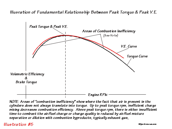
youll quickly see and get to both understand what the changes you made did, and see and anticipate too some extent what changes may be needed, but keep in mind each change effects the other systems too some extent and youll need to find the correct compromise, that balances the result while arriving at a compromise that the engine wants to make its best power, how the vacuum readings change under the throttle bores obviously will effect air flow rates and both the air velocity and the air flow through the carbs throttle bores to a great extent control how fuel is drawn through each system, if it was a steady rpm, you could easily match flow with demand, but because both the engine rpms and the work load on the engine constantly changes youll find that graphing tool very helpful, just keep in mind
http://members.tccoa.com/392bird/tuning.htm
http://www.junkyardgenius.com/holley/tune01.html
http://members.tccoa.com/392bird/tuning.htm
http://www.junkyardgenius.com/holley/tune01.html
Last edited:
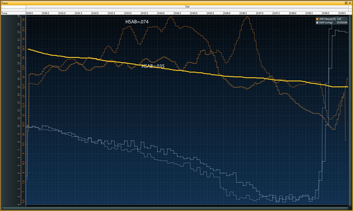
"What do you think is causing the lean spot at 0:05.5 - 0:06.5?"
wrong , slightly too lean, or opening a bit late, for that application power valve would be my first guess
jet selection controls fuel but power valves add additional flow as the air volume increases and plenum vacuum drops off
wrong , slightly too lean, or opening a bit late, for that application power valve would be my first guess
jet selection controls fuel but power valves add additional flow as the air volume increases and plenum vacuum drops off
8
87vette81big
Guest
Don't Get Busted Street Racing Today Rick in the T-Bucket .
Have a choice to stop or keep going.
I have floored it before and left 5.0 behind till no more headlights.
Bye Bye.
Small gas rank in the T.
Don't forget.
Have a choice to stop or keep going.
I have floored it before and left 5.0 behind till no more headlights.
Bye Bye.
Small gas rank in the T.
Don't forget.
The sharp orange line is AFR-1 and has the change from PV6.5 to PV7.5.
The fuzy wider orange line is AFR-2 and represents the last test before the change above.
Note: I didn't label the plots, so if you can't distinguish between AFR-1 and AFR-2, let me
know so I can go back and label them. Getting lazy after 27 test runs now.

Between the blue line and the short white line the vacuum is bouncing around 7.5 inhg.
The two yellow lines represents the time I spent at full throttle and AFR line goes rich in
a hurry. The only thing changing is RPM.

The fuzy wider orange line is AFR-2 and represents the last test before the change above.
Note: I didn't label the plots, so if you can't distinguish between AFR-1 and AFR-2, let me
know so I can go back and label them. Getting lazy after 27 test runs now.
Between the blue line and the short white line the vacuum is bouncing around 7.5 inhg.
The two yellow lines represents the time I spent at full throttle and AFR line goes rich in
a hurry. The only thing changing is RPM.
Looking very good... What do you think is causing the lean spot at 0:05.5 - 0:06.5?
I'm beginning to think it's the emulsion tube. I tried the HSAB because it was easy and
I wanted to see the effects of the HSAB's. So I made a big change of 3.5 times more
Flow Area, see graphic.
The change of the HSAB of 3.5 times bigger in flow area created a change that showed up
almost (not for 1 sec) for the entire test, it went leaner. Getting so lean at two points reaching
16:1 AFR. I felt it stumble once at the 2nd time the AFR went to 16:1. It happened right
before getting to full throttle. I checked a spark plug to see if I could see any aluminum, but
wasn't sure what I was looking for. It looked just like it always does.

the ideal fuel air ratio will be much closer to the thicker and more consistent orange line I added, too your posted data pictured, obviously the HSB.035 provides a closer, match to the intended fuel curve.
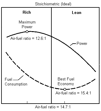
the goal is to provide a slightly lean fuel/air mix to prevent spark plug fouling, get decent cruising mileage, and achieve low emissions in the lower rpm ranges where you'll spend the vast majority of time while driving on the street, yet cause a totally predictable and consistent enriching of the mix ratio as the loads and rpms increase to enhance power and reduce the tendency to get into detonation.
yes my computer graphic skills SUCK!
but at idle you should be running a bit lean and as the rpms increase consistently and predictably transition from about 14.7:1- to provide decent emissions and little chance of plug fouling and decent mileage, too a richer F/A ratio closer to 12.5:1 by 5000 rpm or so and have a matching compatible ignition advance curve, to provide max potential power/torque and some resistance to entering detonation as the richer f/a ratio tends to be be a bit less likely to initiate detonation.
yes this does take some ADJUSTMENTS (TUNING SKILLS) which YOU OBVIOUSLY HAVE!
but because your dealing with several independent yet interlocked fuel supply routes in that carburetor your forced to adjust what is in effect about 4 separate functional systems to provide a predictable average that falls on or near the goal. the fact that each sub-system covers only a small part of the rpm range and that plenum vacuum levels and throttle position are constantly changing makes this part science and a bit of an art!
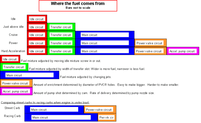
HOTROD MAG POSTED THIS USEFUL INFO
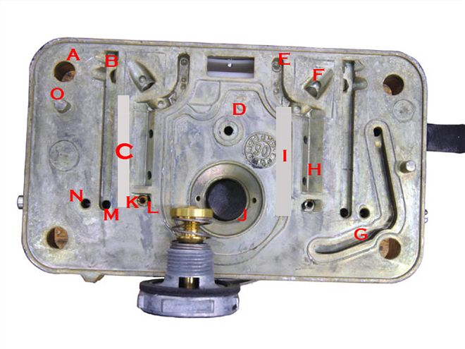
(B) Idle downleg:
This passageway feeds fuel to both the idle discharge port and the idle transfer slot.
(C) Idle well:
Fuel from this well travels to the top of the metering block, then turns 180 degrees and mixes with air from the idle air-bleed into the circuit.
(D) Accelerator pump passage:
This transfers fuel from the accelerator pump to the outlet nozzle.
(E) High-speed air-bleed:
Air from the high-speed bleed enters the metering block here to be mixed with the fuel as it climbs the emulsion tube.
(F) Passage to booster:
This channel transfers fuel from the main well to the booster
(G) Ported vacuum passage:
This connects the ported vacuum source in the throttle body to the outlet where this can be routed to a source like vacuum advance.
(H) Parallel air well:
Air is introduced into the main well through these two holes.
(I) Main well:
Fuel collects here after passing through the main jet.
(J) Power valve channel:
This is where the power valve is located. The two small holes are the power valve channel restrictors (PVCR) that determine the amount of fuel added to the main metering circuit when the power valve opens. This valve determines when additional fuel is added to the main circuit.
(K) Idle restrictor channel:
Fuel from the main circuit passes through this short channel and through a small brass restrictor (L) that acts as the idle circuit jet.
(M) Idle transfer slot discharge:
Idle fuel exits the metering block to deliver fuel to the transfer slot.
(N) Idle fuel discharge port:
Idle fuel exits the metering block and enters the carburetor main body for carb idle fuel below the throttle blades.
(O) Dowel pin:
Two pins locate the metering block on the carburetor main body.
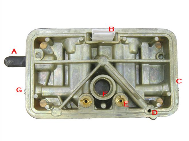
Bowl Side of Metering Block
(A) Timed spark port:
This outlet supplies ported manifold vacuum for distributor vacuum advance only after the throttle is opened slightly.
(B) Vent whistle:
This plastic vent piece vents the float bowl area and also prevents fuel from splashing into the primary venturi under hard acceleration.
(C) Idle mixture screw:
This adjuster screw meters the amount of fuel and emulsified air delivered to the engine at idle.
(D) Accelerator pump entry point:
This is where the fuel from the accelerator pump enters the metering block, traveling up that adjacent diagonal port to the center hole on the opposite side of the metering block.(E) Main jets:
These are the replaceable main jets used to trim the main metering system.
(F) Power valve:
Fuel enters the power valve enrichment circuit from the float bowl.
(G) Other idle mixture screw:
This adjuster screw meters the amount of fuel and emulsified air delivered to the engine at idle.
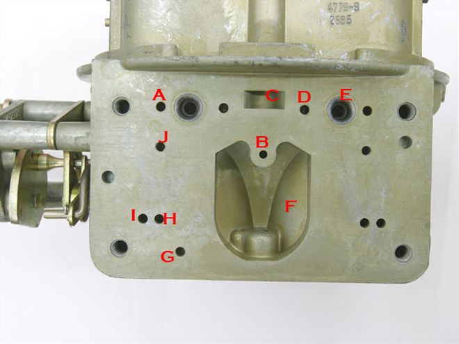
Carb Main Body
(A) Idle air passage:
Air from the idle air-bleed enters the metering block here.
(B) Accelerator pump discharge passage:
Fuel from the accelerator pump enters the main body of the carb here and travels up to the squirter.
(C) Fuel bowl vent:
This vent places atmospheric pressure on the fuel in the float bowl.
(D) High-speed air-bleed passage:
This is where air from the high-speed air-bleed enters the metering block.
(E) Booster venturi inlet: Emulsified fuel from the main well enters the booster through this passage.
(F) Power valve vacuum well:
Intake manifold vacuum is present in this cavity. When the throttles are opened and vacuum drops off in this well, the power valve opens.
(G) Timed spark port:
This hole delivers manifold vacuum only after the throttle is opened past curb idle. This is normally the outlet port for vacuum advance.
(H) Idle transfer slot to discharge:
This port delivers fuel to the idle transfer slot in the throttle body that is uncovered under light throttle.
(I) To curb idle:
Idle fuel enters here from the metering block to the curb idle discharge point on the throttle body.
(J) Auxiliary air:
This hole is used only with an auxiliary idle air-bleed circuit.
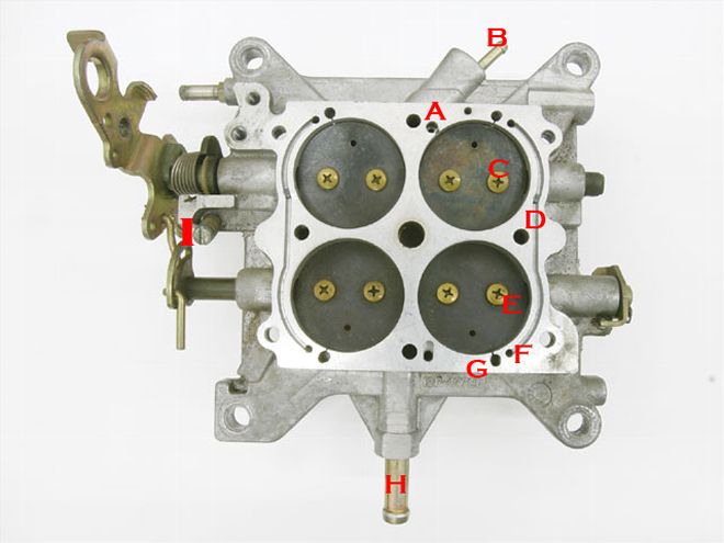
(A) Power valve vacuum port:
This connects the manifold vacuum to the power valve. This is also where newer Holley carbs are fitted with a blowout protection check ball to protect the power valve.
(B) Full manifold vacuum source:
Outlets for constant manifold vacuum.
(C) Primary throttle blades:
All air flows through these blades at part throttle up to a given percentage of throttle opening.
(D) Curb idle speed screw:
This sets the idle speed on the primary side.
(E) Secondary throttle blades:
Controlled by either mechan-ical or vacuum actuation.
(F) Secondary throttle stop:
Small adjustment screw that is a stop for the secondary throttle blades.
(G) Curb idle transfer passage:
Machine passage for idle fuel discharge to secondary side with two-port idle mixture screws for more even idle fuel entry into engine.
(H) Idle transfer slot:
This is where idle fuel enters as the primary throttle blades are opened for part-throttle operation.
(I) Full manifold vacuum source:
Outlets for constant manifold vacuum.
(J) Curb idle discharge:
This passage leads to the small hole underneath the throttle blades where the idle fuel enters the engine.
related useful links
http://garage.grumpysperformance.com/index.php?threads/holley-annular-vs-down-leg-boosters.5229/
http://www.enginebuildermag.com/2008/07/carburetor-tuning-the-airfuel-equation/
http://documents.holley.com/techlibrary_carburetor_tech_info.pdf
http://www.bob2000.com/carb.htm
http://www.hotrod.com/how-to/engine/ccrp-0807-holley-carburetors-basics-guide/
the goal is to provide a slightly lean fuel/air mix to prevent spark plug fouling, get decent cruising mileage, and achieve low emissions in the lower rpm ranges where you'll spend the vast majority of time while driving on the street, yet cause a totally predictable and consistent enriching of the mix ratio as the loads and rpms increase to enhance power and reduce the tendency to get into detonation.
yes my computer graphic skills SUCK!
but at idle you should be running a bit lean and as the rpms increase consistently and predictably transition from about 14.7:1- to provide decent emissions and little chance of plug fouling and decent mileage, too a richer F/A ratio closer to 12.5:1 by 5000 rpm or so and have a matching compatible ignition advance curve, to provide max potential power/torque and some resistance to entering detonation as the richer f/a ratio tends to be be a bit less likely to initiate detonation.
yes this does take some ADJUSTMENTS (TUNING SKILLS) which YOU OBVIOUSLY HAVE!
but because your dealing with several independent yet interlocked fuel supply routes in that carburetor your forced to adjust what is in effect about 4 separate functional systems to provide a predictable average that falls on or near the goal. the fact that each sub-system covers only a small part of the rpm range and that plenum vacuum levels and throttle position are constantly changing makes this part science and a bit of an art!
HOTROD MAG POSTED THIS USEFUL INFO
(B) Idle downleg:
This passageway feeds fuel to both the idle discharge port and the idle transfer slot.
(C) Idle well:
Fuel from this well travels to the top of the metering block, then turns 180 degrees and mixes with air from the idle air-bleed into the circuit.
(D) Accelerator pump passage:
This transfers fuel from the accelerator pump to the outlet nozzle.
(E) High-speed air-bleed:
Air from the high-speed bleed enters the metering block here to be mixed with the fuel as it climbs the emulsion tube.
(F) Passage to booster:
This channel transfers fuel from the main well to the booster
(G) Ported vacuum passage:
This connects the ported vacuum source in the throttle body to the outlet where this can be routed to a source like vacuum advance.
(H) Parallel air well:
Air is introduced into the main well through these two holes.
(I) Main well:
Fuel collects here after passing through the main jet.
(J) Power valve channel:
This is where the power valve is located. The two small holes are the power valve channel restrictors (PVCR) that determine the amount of fuel added to the main metering circuit when the power valve opens. This valve determines when additional fuel is added to the main circuit.
(K) Idle restrictor channel:
Fuel from the main circuit passes through this short channel and through a small brass restrictor (L) that acts as the idle circuit jet.
(M) Idle transfer slot discharge:
Idle fuel exits the metering block to deliver fuel to the transfer slot.
(N) Idle fuel discharge port:
Idle fuel exits the metering block and enters the carburetor main body for carb idle fuel below the throttle blades.
(O) Dowel pin:
Two pins locate the metering block on the carburetor main body.
Bowl Side of Metering Block
(A) Timed spark port:
This outlet supplies ported manifold vacuum for distributor vacuum advance only after the throttle is opened slightly.
(B) Vent whistle:
This plastic vent piece vents the float bowl area and also prevents fuel from splashing into the primary venturi under hard acceleration.
(C) Idle mixture screw:
This adjuster screw meters the amount of fuel and emulsified air delivered to the engine at idle.
(D) Accelerator pump entry point:
This is where the fuel from the accelerator pump enters the metering block, traveling up that adjacent diagonal port to the center hole on the opposite side of the metering block.(E) Main jets:
These are the replaceable main jets used to trim the main metering system.
(F) Power valve:
Fuel enters the power valve enrichment circuit from the float bowl.
(G) Other idle mixture screw:
This adjuster screw meters the amount of fuel and emulsified air delivered to the engine at idle.
Carb Main Body
(A) Idle air passage:
Air from the idle air-bleed enters the metering block here.
(B) Accelerator pump discharge passage:
Fuel from the accelerator pump enters the main body of the carb here and travels up to the squirter.
(C) Fuel bowl vent:
This vent places atmospheric pressure on the fuel in the float bowl.
(D) High-speed air-bleed passage:
This is where air from the high-speed air-bleed enters the metering block.
(E) Booster venturi inlet: Emulsified fuel from the main well enters the booster through this passage.
(F) Power valve vacuum well:
Intake manifold vacuum is present in this cavity. When the throttles are opened and vacuum drops off in this well, the power valve opens.
(G) Timed spark port:
This hole delivers manifold vacuum only after the throttle is opened past curb idle. This is normally the outlet port for vacuum advance.
(H) Idle transfer slot to discharge:
This port delivers fuel to the idle transfer slot in the throttle body that is uncovered under light throttle.
(I) To curb idle:
Idle fuel enters here from the metering block to the curb idle discharge point on the throttle body.
(J) Auxiliary air:
This hole is used only with an auxiliary idle air-bleed circuit.
(A) Power valve vacuum port:
This connects the manifold vacuum to the power valve. This is also where newer Holley carbs are fitted with a blowout protection check ball to protect the power valve.
(B) Full manifold vacuum source:
Outlets for constant manifold vacuum.
(C) Primary throttle blades:
All air flows through these blades at part throttle up to a given percentage of throttle opening.
(D) Curb idle speed screw:
This sets the idle speed on the primary side.
(E) Secondary throttle blades:
Controlled by either mechan-ical or vacuum actuation.
(F) Secondary throttle stop:
Small adjustment screw that is a stop for the secondary throttle blades.
(G) Curb idle transfer passage:
Machine passage for idle fuel discharge to secondary side with two-port idle mixture screws for more even idle fuel entry into engine.
(H) Idle transfer slot:
This is where idle fuel enters as the primary throttle blades are opened for part-throttle operation.
(I) Full manifold vacuum source:
Outlets for constant manifold vacuum.
(J) Curb idle discharge:
This passage leads to the small hole underneath the throttle blades where the idle fuel enters the engine.
related useful links
http://garage.grumpysperformance.com/index.php?threads/holley-annular-vs-down-leg-boosters.5229/
http://www.enginebuildermag.com/2008/07/carburetor-tuning-the-airfuel-equation/
http://documents.holley.com/techlibrary_carburetor_tech_info.pdf
http://www.bob2000.com/carb.htm
http://www.hotrod.com/how-to/engine/ccrp-0807-holley-carburetors-basics-guide/
Last edited:
8
87vette81big
Guest
Grumpys last Bar Graph is Real Helpfull To You Rick.
Just a side note of my own experience with Holley Carbs.
The Factory Holley Jets & Master Jet pack kits,
The main jet orfice sizes have tolerances.
Use your Go No Go plug guages and check .
AED Holley Racing Carbs sells nice precise main jets.
They get thier parts From BLP BO LAWS IN FLORIDA .
The Best is made where Grumpy is.
Sold to other High End Carb Builders.
8
87vette81big
Guest
Good point Grumpy.
There may be a Fuel supply problem on demand driving the T-bucket Hard.
1G force would do it.
Rick still has the Holley Red Fuel Pump.
Without a Fuel pressure guage in drivers view you can not see Pressure Drop.
Fuel volume to carb drops accordingly.
Holley Red set for 6-7 psi I recall.
Internal bypass regulated in the pump itself.
Came across this info while searching for information on "Emulsion Hole Theory".
http://forums.vwvortex.com/showthread.php?5210682-A-simple-way-of-tuning-with-Emulsion-Tubes
David Vizard explains emulsion holes in the video below.
It's hard to read it's so small, but if you need to know like myself, it can be done.


It comes from this book about Webers.
http://www.amazon.com/Weber-Carbure...TF8&qid=1299554062&sr=1-1&tag=viglink20344-20
http://forums.vwvortex.com/showthread.php?5210682-A-simple-way-of-tuning-with-Emulsion-Tubes
David Vizard explains emulsion holes in the video below.
It's hard to read it's so small, but if you need to know like myself, it can be done.
It comes from this book about Webers.
http://www.amazon.com/Weber-Carbure...TF8&qid=1299554062&sr=1-1&tag=viglink20344-20