Unforgiven Project

While researching pump and line sizes , I ran across this informative site which I thought would help
someone else.

https://www.powerperformancenews.co...00-hp-street-engine-big-power-means-big-fuel/

http://injectordynamics.com/articles/fuel-pressure-explained/
Often times the term fuel pressure is used with little understanding of what it really means. This leads to confusion with respect to injector flow rate, and people lose sight of how their injectors really work. Understanding how fuel pressure works and is applied in both re-turn less and return style fuel systems is important if a user wants to properly set up their injector characterization and get predictable fueling. Knowing what to expect also allows a user to diagnose problems with their fuel system and ultimately make the vehicle function as intended.

There are two pressures that people need to consider: rail pressure and effective (or differential) pressure. For the purposes of the rest of this article, it will just be called effective pressure. Rail pressure is self-explanatory; it is the pressure inside the rail. When you stick a fuel pressure sensor on the end of a rail, it is reading the pressure inside of the rail. While this number is important, it is only half of the story.

Effective pressure is the actual applied pressure for the injector, and is the pressure differential ACROSS the injector. Effective pressure is what injector flow rate is ultimately based off of. When an engine is idling, there is a vacuum in the intake manifold. This vacuum pulls fuel out of the injectors, and increases the effective pressure across the injector to a pressure higher than the rail pressure itself. When a supercharged or turbocharged vehicle is in boost, the pressure inside the manifold is trying to push fuel back into injector, resisting the flow and decreases the effective fuel pressure below that of the rail.

This concept is important because it changes how the fuel system needs to be set up in the PCM. There are two generic types of fuel system setups: returnless and return style. A returnless system does just as the name implies and doesn’t return fuel to the tank. Return style systems will bleed excess fuel back to the tank through the regulator. Return style systems hold a big advantage in that with a vacuum/boost referenced fuel pressure regulator, the system can maintain a CONSTANT effective fuel pressure, which can extend the range of fuel injectors and help them function at lower fuel demands as well.

With a return system, the base pressure is set with the engine off, but the pump running. For a GM, this pressure is usually set to 58psi (factory fuel pressure in the rail). The vacuum/boost referenced regulator will help to change the pressure in the rail based on the pressure in the manifold. When an engine is idling, it may be pulling 20 in Hg of vacuum, which translates to roughly 10psi. The reference to the regulator will allow it to adjust and lower the pressure in the rail to 48psi, resulting in 58psi effective pressure, which is the same as the base pressure. When the engine is making 10psi boost, the regulator will adjust and increase rail pressure to 68psi, again resulting in 58psi of effective pressure. The regulator will constantly bleed off pressure inside of the rail to maintain the same effective pressure at all operating conditions. This helps to prevent a loss of effective pressure during wide open throttle, and also helps to prevent injectors from having to run extremely low pulse widths to fuel at idle. A downfall of return systems is the fact that they circulate fuel through a very hot engine bay, ultimately carrying that heat back into your fuel tank.

A return style system that isn’t variable will maintain a certain pressure inside the rail, regardless of what is happening in the manifold. For instance, take a GM system with the standard 58psi in the rail (usually there is a mechanical regulator near the pump to bleed pressure back into the tank and keep the rail itself at 58psi). No matter what operating condition (short of demanding more fuel than the pump can supply), pressure in the rail will always be 58psi (or pretty close). When idling at 20 inHg, this means effective pressure will rise to 68psi because the vacuum in the manifold is adding 10psi to the rails 58psi. This requires injectors to pulse shorter so as to not over fuel the engine and cause a rich condition. By contrast, when a naturally aspirated engine is wide open throttle, the manifold pressure is not in vacuum or in boost, so the effective pressure is the 58psi of rail pressure and nothing more. However, a boosted engine at 10psi will be resisting the fuel, causing effective pressure to drop to 48psi from the 58psi in the rail. This lowers the ultimate output of the injectors.

Some return less systems will actually vary the pump output to emulate a referenced system, or to offer more fuel pressure at higher demands and less fuel pressure at lower demands. Ford fuel systems modulate the pump in an effort to maintain effective fuel pressure at 3 bar. The Corvette ZR1 runs fuel pressure in the 30s until an increased demand is on the system, at which point it will ramp the fuel pressure up to 88psi in the rail. Systems like these use sensors that record the fuel pressure, and when combining that pressure with the manifold pressure, the PCM knows what the effective pressure is and will determine a pulse width for the injector accordingly. Systems like these offer the best of both worlds.

Ultimately, what we need to know is the effective fuel pressure in any given situation though. GM uses manifold pressure to subtract away from the rail pressure (which it always assumes is 58psi) to calculate pulse width. By referencing the flow rate table, in which the flow rate at various effective pressures is programmed in, the PCM knows what flow the injector is capable of at any given operating system. To convert a GM vehicle to work with a boost referenced return system, one must simply populate all of the various pressures with the same flow value, since the effective pressure (and consequently injector flow rate) will remain constant, regardless of manifold pressure. Word to the wise, when you see injectors advertised to flow X amount of fuel at a certain pressure, if you have a boosted vehicle, they will actually flow less while in boost unless you have a boost referenced system!

Dave Steck
DSX Tuning
 
Last edited by a moderator:
I got a few pics for tonight.
Mike I snapped a pic of the air dry system I made for when I was painting. The filter on the floor was the last line of defense before I connected my air line.
It was attached on the right side of the system in the middle. Those valves at the bottom where for draining what water had accumulated . The jar and hose are what I use to bleed brakes with. I just add a small amount of brake fluid into the jar and stick the hose into it. On the other end I push the hose over the bleeder screw after I have cracked it open. then just pump the pedal until all the bubbles are done coming out of the bleeder screw. The clear hose makes it easy to see the bubbles, and it is a one man job.
View attachment 12423View attachment 12424

I need to remount and plumb in a new air system along the walls now that they are sheeted.
That oughta work, and I have one of those HF filters myself. Under certain weather conditions, there is a lot of water/condensation.
 
It never fails.. I was getting ready to install the crank last night and discovered that I did not have a main rear seal. So I went to the local autozone
to pick one up and they only had the rubber one, I wanted the viton seal.
So I placed an order thru Summit Racing.
I purchased a new aluminum timing cover and seal kit, a rear main seal, a Moroso 22090 oil pump driveshaft for that M77 oil pump,
and that Canton 20-100 oil pick up.

I am hoping it arrives tomorrow. I want to get the bottom done this weekend so I can check the deck height in order to
pick the correct head gaskets and order them before Monday. That way I will have them before the 4th.
I get a 4 day weekend next week so I should be able to complete the motor less the EFI and fuel system. Barring nothing goes wrong.
 
yeah, but at least we don,t have someone doing his best to stir up constant crap,
and call out other members, making threats etc.
and I don,t have to read then delete much of/or whats posted ,
in 10-15 posts, many days,....that got old real fast
 
I'm kinda glad I did not see what was going on. I did not put thing together till the very end.
 
Back on the motor subject.... I was browsing another forum thread and the guys were talking about what they did for a E85 fuel system.
They were tired of the high prices of billet filters so one guy instead used 1/2" (.020 wall) S.S. tube and a 10 micron screw on filter from Tractor Supply store.
He stated that he only seen a 5 lb pressure drop after the filter. He run pressures up to 75lbs with no problems on his EFI.
He said he even applied 120 psi from his air compressor to see if it would hold and it held.
Kinda dangerous test I thought.


https://www.tractorsupply.com/tsc/product/cim-tek-hydrosorb-filter-kit?cm_vc=-10005

A 25' roll of 1/2" 304 SS tubing from a brewery company is around $36
The ss fittings are around $23 a pair.

https://www.ebay.com/str/NY-Brew-Supply?_trksid=p2047675.l2563

The an hose through Summit was way over $100 and the filters were over $100 each.
I am going to look deeper into this Tractor supply filter and try to look for a down fall of using it.

I was reading that injectors really need a 5 micron filter to protect them, and you just cant go that fine when using E85 fuel.
I have read that E85 flows best down to 40 microns, without affecting pressure. Injectors would not like the dirty fuel that would get
by a filter that size. Especially since E85 is hydroscopic. Any rust that may form in the fuel system that is smaller than 40 microns
would get into the injectors.

Now this TSC filter is 3 1/2" x 3 1/2" x 5" if I remember . It also has 1" inlet and outlet. It also has a paper element which is not recommended for E85 , but I believe the size of the filter would overcome any
pressure losses from the paper element. And being that the fuel lines are made of stainless, Rust would be a non factor.

This is what I have researched so far and I cannot verify That it is the proper way to go.
But I like the prospect of saving money if it is a legitimate way to go with out compromising the system.
 
Wow, that brewing company has some nice stuff and reasonable prices. Here are some examples:

https://www.ebay.com/itm/3-8-OD-Type-316-316L-Stainless-Steel-Straight-Tube-sold-by-the-ft/301081552233?hash=item4619dbe569:g:2IkAAOSwKtVWxOoY
https://www.ebay.com/itm/3-8-OD-x-25-Length-x-020-Wall-Type-304-304L-Stainless-Steel-Tubing-Coil/300309687912?hash=item45ebda2e68:g:ah8AAOSwFNZWxMz1
https://www.ebay.com/itm/3-8-OD-x-50-Length-x-020-Wall-Type-316-316L-Stainless-Steel-Tubing-Coil/290586394836?hash=item43a84c80d4:g:CTgAAOSwzgRWxkVZ
https://www.ebay.com/itm/6-Stainless-Steel-Kettle-Screen-1-2-NPT-Ships-Same-or-Next-Day/292002885656?hash=item43fcba7018:g:Z7MAAOSwWWpZxctf
https://www.ebay.com/itm/1-2-OD-x-50-Length-x-020-Wall-Type-316-316L-Stainless-Steel-Tubing-Coil/300387034278?hash=item45f07664a6:g:sCIAAOSwWTRWxeRT
https://www.ebay.com/itm/1-2-OD-x-028-Wall-Type-304-L-Stainless-Steel-Straight-Tube-sold-by-the-ft/291138335558?hash=item43c9327346:g:A1oAAOSwezVWxN8G
https://www.ebay.com/itm/1-2-OD-x-25-Length-x-028-Wall-Type-304-304L-Stainless-Steel-Tubing-Coil/302275640763?hash=item4661083dbb:g:DDMAAOSwhQhY5o4o
https://www.ebay.com/itm/1-2-O-D-x-50-Length-x-028-Wall-Type-316-316L-Stainless-Steel-Tubing-Coil/291267937238?hash=item43d0ec03d6:g:~TkAAOSwDuJWxPFf
https://www.ebay.com/itm/1-2-O-D-Stainless-Steel-Dip-Tube-for-Homebrew-Beer-Keg-or-Kettle-9-x-4/301907040280?hash=item464b0fd818:g:-FwAAOSwdU1W8sPd:sc:USPSFirstClass!27668!US!-1
https://www.ebay.com/itm/1-2-OD-x-25-Length-x-020-Wall-Type-316-316L-Stainless-Steel-Tubing-Coil/300387035381?hash=item45f07668f5:g:Zu8AAOSwx-9WxeDh
https://www.ebay.com/itm/1-2-O-D-x-25-Length-x-028-Wall-Type-316-316L-Stainless-Steel-Tubing-Coil/291267937049?hash=item43d0ec0319:g:wlcAAOSwB4NWxO85
https://www.ebay.com/itm/1-2-OD-x-50-Length-x-028-Wall-Type-304-304L-Stainless-Steel-Tubing-Coil/291266908982?hash=item43d0dc5336:g:nwoAAOSwFNZWxK~Z
https://www.ebay.com/itm/1-2-OD-x-25-Length-x-020-Wall-Type-304-304L-Stainless-Steel-Tubing-Coil/290507663350?hash=item43a39b27f6:g:KRgAAOSwPc9WxLaj
https://www.ebay.com/itm/Stainless-Steel-1-2-Compression-to-1-2-Compression-Fitting/302730999978?hash=item467c2c78aa:g:dpkAAOSwJTta8GiY
https://www.ebay.com/itm/Dip-Tube-with-Compression-Fitting-for-Beer-Keg-or-Kettle-1-2-Stainless-Steel/291244416475?hash=item43cf851ddb:g:~WMAAOSwxH1UGGFa:sc:USPSFirstClass!27668!US!-1
https://www.ebay.com/itm/2-Piece-Stainless-Steel-Ball-Valve-1-2-Homebrew-Beer-Shutoff-Valve/291891504437?hash=item43f616e535:g:JKgAAOSwNRdX6-T4
https://www.ebay.com/itm/Male-Female-Pipe-Thread-Hose-Barb-Adapters-Various-Sizes-Brass-Stainless-Steel/291548493032?hash=item43e1a4f4e8:m:m7yOSCXtJaregKRn0pNr_Ew:sc:USPSFirstClass!27668!US!-1
 
Grumpy... I am having an anxiety attack today!!
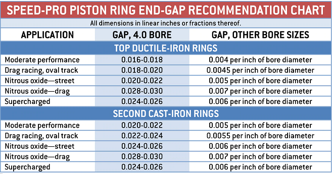
I am going to install the lower end of the motor and am wondering if the ( plasma moly) rings are gapped enough.
I have them all gapped at .026 like we talked about earlier.. which equals .0064 per inch of bore.
With the projected HP of 700.... a ( roots style) blower ( 10-12 psi)...e-85...EFI.. and maybe a 300 shot of nitrous, I am having second thoughts on the gaps not being wide enough.

I have a case of reading tooo much and it is starting to effect my judgement.
Can you give a little advise for reassurance ?

Also... I was going to file 2 small slots on the big end of the rods for another oiling mod to spray the pistons and pin.
I am not sure as to how deep the grooves should be.. I was thinking around .030

Does this sound correct.?
 
,if your in doubt gap them at a bit more clearance, to provide some extra assurance the ring ends won,t butt under high heat.

read these links, and related sub-links

the simple truth, is that any-where from about 4.5-6 thousands gap per inch of bore diameter ,
is about the desired range,
but adding clearance up to about .032-.036 will have almost no detrimental effect ,
on how the engine runs ,that can be measured,
personally I think that .026-.028 you suggested would be just fine, if youll sleep better having that.


ringgss.png

ringgp2.jpg

gaps.jpg


http://garage.grumpysperformance.co...ng-and-basic-piston-ring-info-youll-need.509/

http://garage.grumpysperformance.com/index.php?threads/another-rings-end-gap-question.14994/

http://garage.grumpysperformance.co...g-and-installing-connecting-rods-pistons.247/

http://garage.grumpysperformance.co...piston-to-bore-clearance-on-your-block.14251/
 
Maybe a little blow bye if you go much wider than what you have now. Like Grumpy said--4-5-6- per inch of cylinder bore. I always used the 5/1000 my self WHEN i use to do a lot of engine building even with Blowers. Always ran lots of breathers also.
 
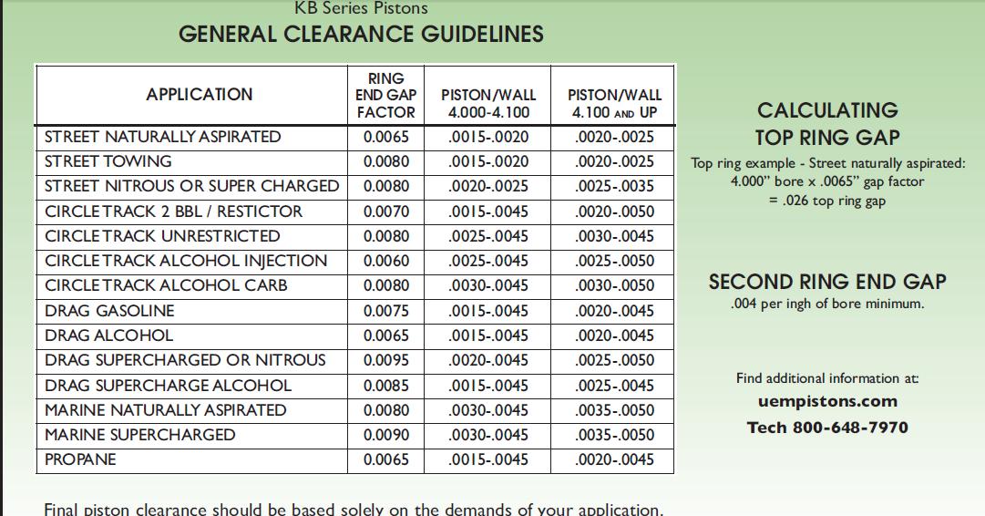
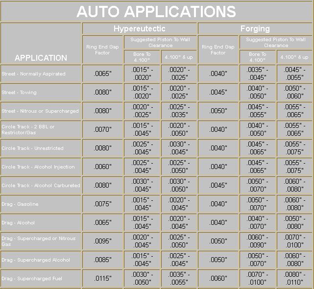
Well I calmed myself down. I got worried when I seen that KB chart calling for .008 per inch.
i'm sticking with the .026. This is what the Wiseco chart indicates, and is what I am using.

Sooo ... this is my report on the motor.
I gathered a few tools together and laid them on a portable table (I forgot I had ) per grumpy's suggestion.

IMG_0430 (1).JPG
 
I modified the rods so it would spray some oil under the pistons. The slots are about .020 deep.

IMG_0431 (1).JPG IMG_0429 (1)arrows.jpg
 
i set the crank in the block ... I ended up with .002- .0023 with the plastic gauge..but my bore gauge shows a solid .0025

IMG_0437 (1).JPG IMG_0435 (1).JPG
 
I installed all the pistons ... I have to check clearances tomorrow cause I ran out of time today, but I did get to check the deck height.
The pistons are all in the hole .002 as I requested them to do. That makes my deck 9.017

My pistons are .015 taller than other pistons, that is the reason for an odd number for my zero deck height.

The number below shows .0035 but I found AFTER THE PIC THAT THE PISTON WAS ROCKED.
I also found the the piston can rock upwards of .005 out of the hole at the edge.
I am going to use a .040 MLS gasket
I will order them tomorrow.

The cam and timing gears are in awaiting to be degreed in.

the last pic is just a veiw of the block so far.

IMG_0441.JPG IMG_0444.JPG
 
The pistons are all in the hole .002 as I requested them to do. That makes my deck 9.017
My pistons are .015 taller than other pistons, that is the reason for an odd number for my zero deck height.

I am going to use a .040 MLS gasket.

Nice, really nice. And as to whether you did it on purpose or by accident, the taller pistons worked out great because I'm not a fan of machining large amounts from the decks, making them thinner and weaker. And .042" for quench - perfect!
 
Thank you Mike! I have to admit, the taller pistons were another persons idea. After I thought about it for abit ,I liked the idea
of not milling too much off the deck. It worked out well.

My clearances were bothering me all day yesterday and last night. I used my dial bore gauge to check the main bearing clearances
against the mic'ed crank and it showed I would have .0025

The plastic gauge showed approximatly .0018-.002
That is tight!

I think I know what happened... During assembly, I laid a piece of plastic gauge on the main journals, then set the caps on and began to torque them
down in sequence. I then removed the caps and took measurements against the chart.
I now believe this was the WRONG way to measure..because the bearings and crank were not actually seated yet, and I think the crank
was moving around and pushing on the caps that were not torqued yet.
I believe the proper way would be to torque all the caps down, and one at a time, remove a cap and install the plastic gauge, then retorque the
cap, Then remove it and check the clearance. After measurements are taken, replace and torque cap, and repeat the next cap.
I am going to do this when I get back in the barn.

It took about 33lbs to get the assembly rotating and it took 28lbs to keep it rotating using a beam style torque wrench. Before I installed the
pistons I could rotate the crank with two fingers. It turned real smooth and free. After the piston and rings were installed I used the beam wrench
and came up with the said numbers.

The M77 oil pump pick up will arrive today , so I can start that install, and get the measurement to the pan floor. I found the correct oil drive shaft
and have it on hand.. it was .125 longer than the M55 pump. I took measurements off the old pump and compared them to the new pump for verification.
Head gaskets and a few other Items are being ordered today so I can have them before the 4th of July holiday. I have a window of oppertunity
to set the block back into the truck this weekend.
 
Back
Top