Well, I'm back where I was a week ago

Timing cover and oil pan are back into place. New pan gasket, timing cover repainted and I also installed a new balancer seal. I used socket/hammer to install it last time and it had a dent in it - not large but it bugged me, so this time I used my press for an easy smooth install. Actually, this cover/pan install was like a textbook version - everything fit perfectly, all bolts lined up/torqued smoothly and the small bead of rtv in the corners squeezed out just right.


So, next week I will resolve all the pushrod drama, I need to move forward and finish this engine.
What I want to do is compare what I see as 3 methods of setting pushrod length, with 2 of them so far giving entirely different results. The lack of consistency is what has been bugging me. I'll return back to this post and edit accordingly. I will use the Melling solid roller lifter for all 3 methods, so I can use the installed valve springs - if I can establish proper length using the Melling, then I can repeat the same process for the Morels.
Also noted are two perspectives - that proper length/geometry should create a centered witness mark or proper geometry is set on rocker trunion/roller relation to lift and therefore final witness mark is secondary. But it still cannot be closer to 020" to the stem edge.
So here's what I'm looking at - to be edited.....
Method 1 - Proform tool / setting base lobe rocker at top 1/3 line of valve stem
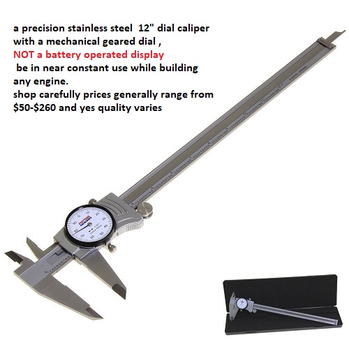
This method is a simple check that uses a plastic tool to set length of adjustable pushrod. One side of tool rests on valve stem and the pushrod is adjusted to touch the other side. The one I bought "should" be a 1.7 ratio for BBC, but my question is what rocker is it modeled for? Stock steel or aftermarket roller, and if roller, then which one?

The other part of this is simply visually setting the rocker up to get the witness mark about 1/3 down on the stem, with the idea to get the overall movement close to center stem.
 Method 2 - Straub video - setting base lobe rocker arm at 1/2 lift (90d perpendicular half lift)
This method takes gross lift divided by 2 and adjusting rocker nut turns accordingly. 1 turn of nut on 7/16 stud = .050"
In my case, GL = .578", divided by 2 = .289".
.289" divided by .050 = 5.78 turns without preload, 6.78 turns with recommended 1 turn Morel lifter preload. But using the solid Melling roller, it would be 5.78 turns.
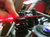
The rocker arm axis is very close but not exactly perpendicular to the stem at half lift. My further checks will use a laser line on top of retainer to try to get an accurate parallel measurement.

And the witness mark on a full roll is close.
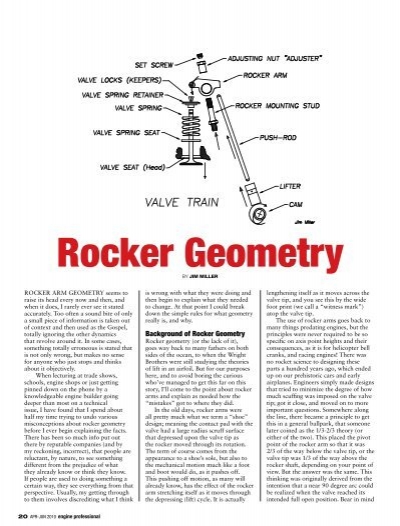
 Method 3 - Miller method of setting base lobe rocker arm at 1/2 net lift below top of spring retainer
The complete article is linked in previous post.
This method takes the net lift (which I take to be lobe lift on hydraulic - solid would subtract valve lash I think), divided by 2. This dimension is where the trunion centerline is set using adjustable pushrod.
That number is the "trunion reference" dimension in the figure below.
So my case again, .578"/2 = .289" which is what my trunion reference point would be set to.
Back thinking on net lift, I will re-check lift at valve stem to use this number as well to see where that puts the trunion reference point. I believe that the net lift at valve is usually less than actual lobe lift due to parts flex, discrepancy in rocker ratio, etc. So that will be an interesting comparison. I will also look at the witness pattern, but according to Miller, this is not the governing factor of proper geometry. However, I think it should be fairly close - if it's way off almost off the edge, then something is not right.

His directions for measurement below.
One difference is that the Morel preload is recommended to be .050" (1 full turn) vs the .020" in the text.

A couple of quotes from J. Miller:


 engineprofessional.com

 engineprofessional.com