I could fill chapters on these subjects, but its basically not something the average engine builder assembling off the shelf parts needs to be overly concerned with other than to understand the potential power may change due to the parts selected and the careful assembly and measurement during the engine assembly will effect his results. I think you can assume having minimal quench clearance to maximize the effect, is FAR less important on a low compression engine than on a race engine by the simple fact that most factory produced production engines have a quench or squish clearance thats so large that its most likely NOT producing its full potential advantage to the combustion process
that a tighter squish/quench clearance would produce, most likely because its far easier to build and assemble engines and have fewer interference or clearance and binding issues to do so!
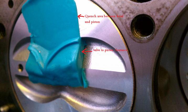
your engines tendency to get into detonation is the result of higher effective compression that the fuel octane your using can permit, but your piston is only compressing the fuel air mix AFTER both valves seat.detonation is a condition that occurs as the result of both cylinder temperature compressions effect on your fuel/air ratio and several other factors that cause fuel to self ignite under some conditions, lowering the EFFECTIVE compression , lowering the heat in the combustion chamber , or designing the engines quench,squish,turbulence and other factors to greatly reduce the engines tendency to get into detonation will obviously help prevent it.
TRY AND GET THE QUENCH DISTANCE BETWEEN the heads and pistons at TDC. to fall between,
as a general rule
shoot for a quench of
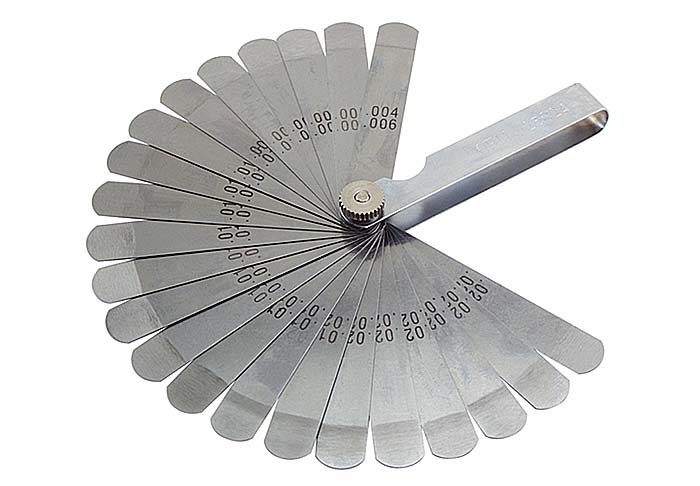
Minimum .045", max .060", more important is the squish area and chamber shape.
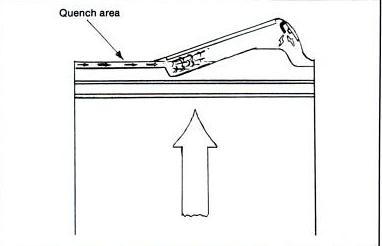
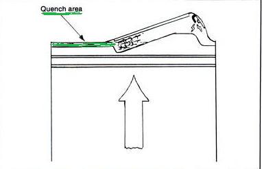
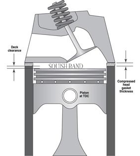
RANGE , DON'T GO INSANE IF it's ONLY POSSIBLE WITH YOUR COMPONENT CHOICES TO GET DOWN TO .050, QUENCH, its marginally less effective but still works) on most engines,the idea is to force a compressed jet of that fuel air mix, trapped between the almost contacting surfaces,(PISTON ALMOST HITTING THE HEAD) into the combustion chamber at high speed this increased turbulence increases the burn speed in the combustion chamber, and the two surfaces so close together cool the trapped gases between them ,just enough to slow or prevent detonation, reducing the distance the flame front must travel ACROSS the cylinder allows less ignition advance to be used so, mechanical EFFICIENCY to be improved
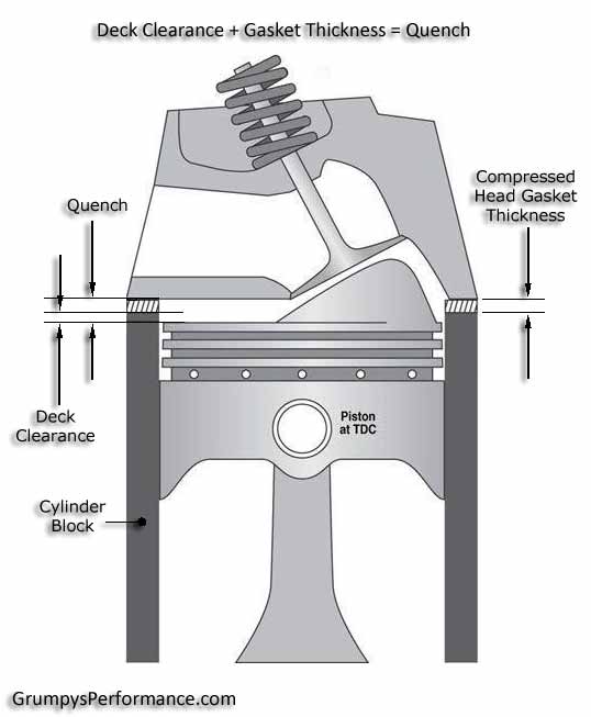
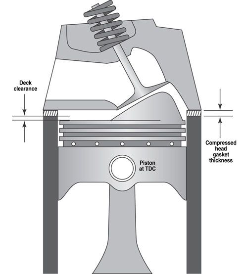
BTW When a head gasket thickness is listed its supposed to be the compressed gasket thickness ,this can be important in determining quench distance.
It might help to keep in mind, the amount of TIME the piston, is in close proximity to the cylinder head, remember the 4 cycle ,
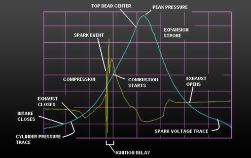
or 720 degrees the crank turns, the the very brief time the piston spends on the power stroke, there is only about 25-40 degrees of that 720 degree cycle here theres near peak pressure above the piston, and even at idle speeds (lets assume 800 rpm) the power stoke or peak pressure , is only lets say 35 degrees in a 720 degree cycle thats happening repeatedly 13.3 times per second.
now at 7000 rpm, thats happening 58.3 times a second, think it through, about 5% of the whole 720 degree repetitive cycle
has significant torque producing pressure above the piston, exerting thrust against the crank shaft journal,
the other 95% is required just to prepare the cylinder to fire and exert that pressure pulse, theres a power pulse at each 90 degree turn of the cranks rotation, on every other time it reaches TDC.
there's about a 600-700 PSI peak pressure above the piston, that rapidly drops off as the piston descends on the power stroke as the fuel burns, expending its energy, by the time the piston reaches mid stroke pressure is reduced to far less than it was during the first 30 degrees of rotation.
if you have a 4.25" bore 454 BBC theres about 14 sq inches of piston surface are, thus about 8500 lbs or more
(depending on the F/A ratio and compression )
of force very briefly above the piston, every 90 degrees of rotation.
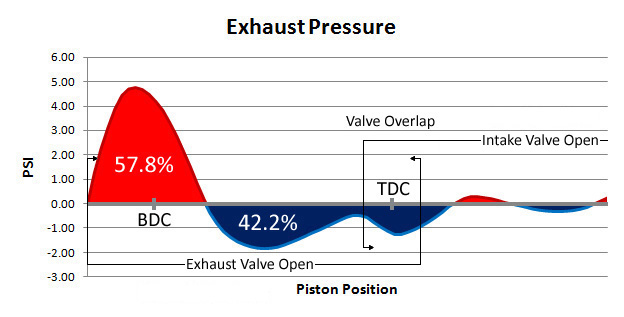
that pressure drops of rapidly as the piston descends down the bore and after the exhaust valve opens it drops below atmospheric pressure briefly

2. COMBUSTION QUALITY EVALUATION FOR SPARK IGNITION ENGINES
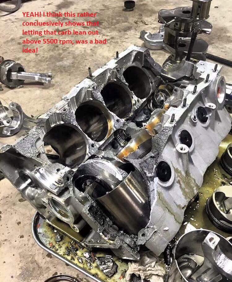
If you take the time required to understand your options and having built an engine with close to ideal quench youll find its slightly less likely to get into detonation conditions that can quickly destroy a piston, resulting in massive engine failure.
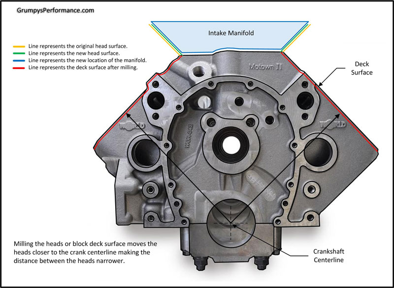
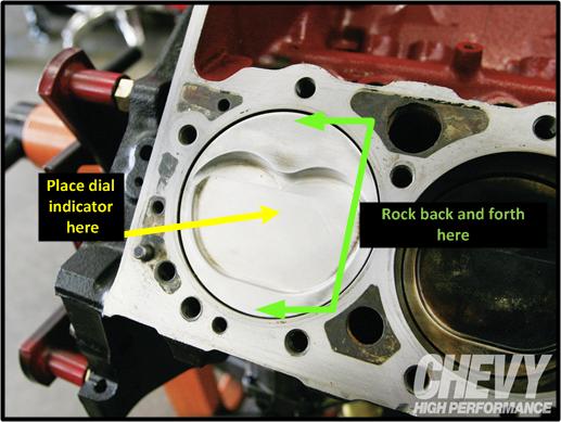
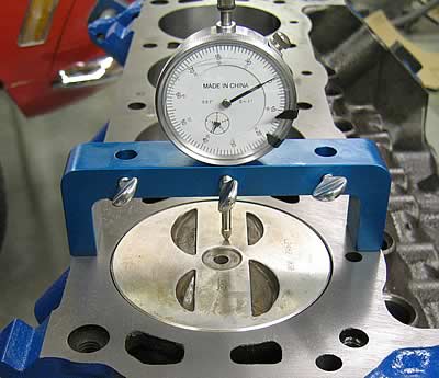
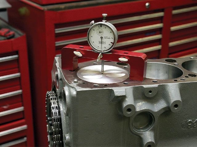
the first step is having the block decks accurately measured and if necessary machined so the block decks level and parallel with the crank center line.
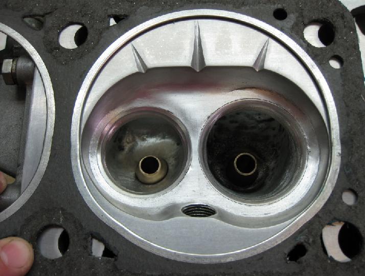
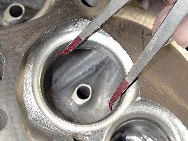
in this example directly below the plugs GROUND electrode is ALMOST EXACTLY OPPOSITE, OF THE IDEAL INDEXED location , as its located wher the piston has the best chance of contacting the ground electrode,
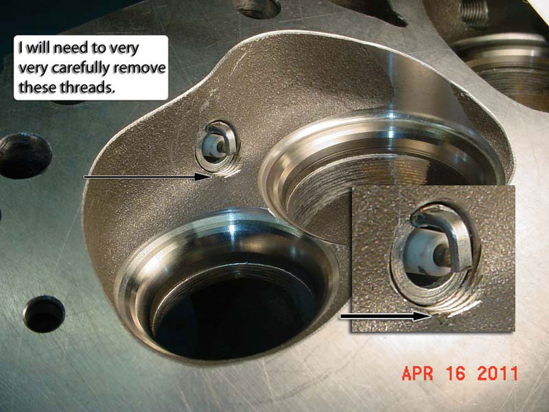
example , now ideally youll want the ground electrode facing the roof of the combustion chamber for max clearance and flame propagation
similar too...
read the links
http://www.hotrod.com/articles/fuel-octane-rating-comparison/
http://garage.grumpysperformance.com/index.php?threads/aluminum-heads-polishing-and-porosity.14689/
if the blocks 100% correctly machined, and you get a wide variation in piston to deck heights , remember theres some variation in both piston pin height and connecting rod length, if for example you find SOME PISTONS .003 AND SOME AT 009, that MIGHT BE A RATHER HIGH VARIATION
It would indicate the block deck needs to be machined or perhaps the pistons and rods could be interchanged (longer rods, re matched with shorter piston pin heights) to get a lower average variation
you should be trying to get a .038-.044 quench height, personally I try to be on the .042-.044 range.
if the pistons sticking above the block deck your calculation subtracts the distance from the compressed head gasket thickness, if its below deck you add that distance to the head gasket thickness to arrive at the quench distance.
KEEP in mind your engines effective or dynamic compression and your effective quench distance, the materials in the cylinder head, coolant and oil temps., ,ignition advance curve,plus the engines combustion chamber temperature and fuels octane level plus several other factors determine the engines detonation threshold or tolerance, each component choice effects the complete combo[/color]
http://cochise.uia.net/pkelley2/DynamicCR.html
"Determining seat timing: Since the early days of the internal combustion gasoline engine, engineers have known that the Otto four stroke engine is compression limited and that the quality of the fuel used determines the CR at which the engine could operate. However, it is not the Static CR but the actual running CR of the engine that is important. Compression of the air/fuel mixture cannot start while the intake valve is open. It may start slightly before the intake valve is fully seated. However, there is no easy way to determine this point so using the advertised duration number provided by the cam manufacture is the next best thing. Most cam grinders use .006" of tappet lift (hydraulic cam), although some use other values, with .004" being a common one. This duration is often referred to as the "seat timing". We will used advertised duration for calculating the DCR. "
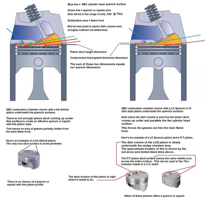
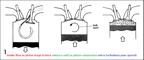
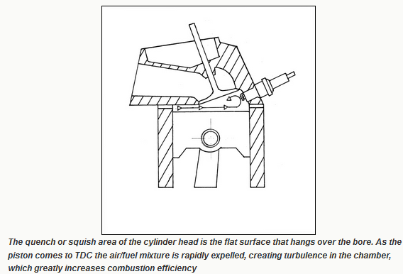
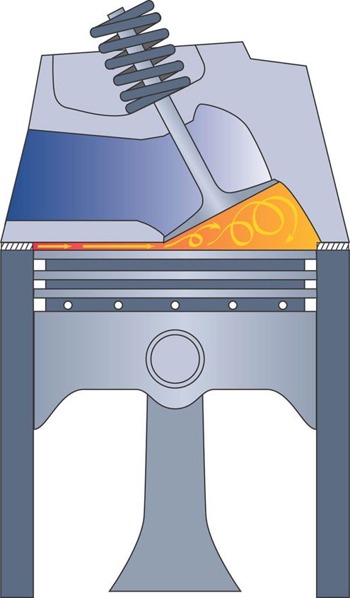
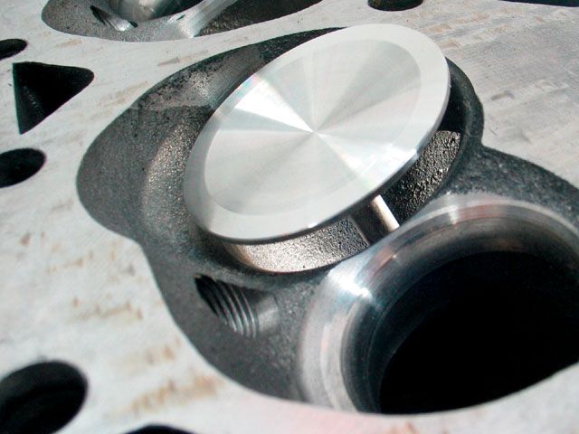
quench is basically achieved by momentarily allowing the rotation of the piston past TDC so its placing the piston and heads flat matching surfaces as the piston rotates past tdc, so close too each other that and compressed gasses and air are forced out from between the surfaces in a near collision,between the surfaces , as the rapid exiting of the compressed fuel air mix has both a cooling effect and the turbulence increases the combustion, plus heat absorbing factors and lack of space between the surfaces prevents the fuel/air mix from burning, it also reduces the distance the flame front needs to travel once ignition starts, because the SQUISH has forced much of the previously trapped fuel/air mix into the combustion chamber and away from the cylinder wall, and the increased turbulence that results, speeds the burn in that smaller combustion chamber.
squish is the rapid forced displacement of the fuel/air mix from the quench area into the smaller main combustion chamber which rapidly increases turbulence and the burn speed ,by increasing the flame front speed,much as throwing a cup of gas into a camp fire would

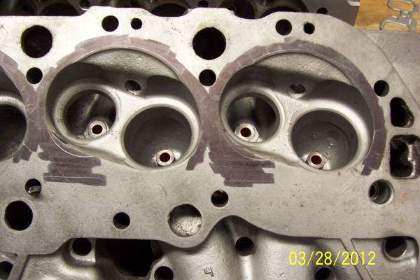
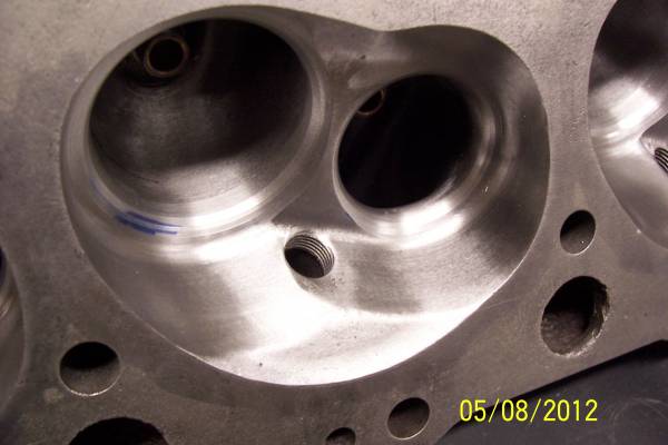
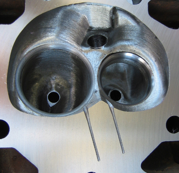
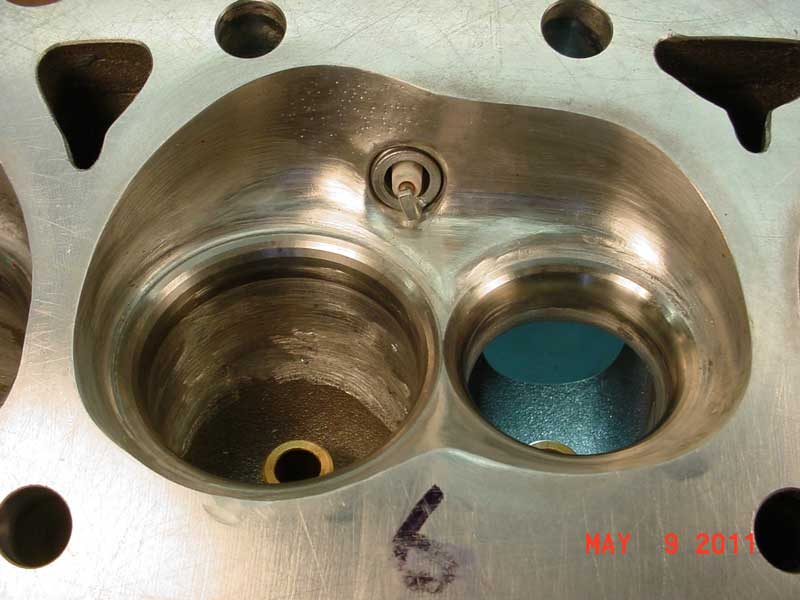
Any decent, experienced machine shop can measure your cylinder heads combustion chamber,
and calculate the required clearances after measuring your heads combustion chamber, and then do the correct machine work on your piston domes,
machining the domes for adequate,spark plug,clearance,
this is a very common issue and easily resolved,
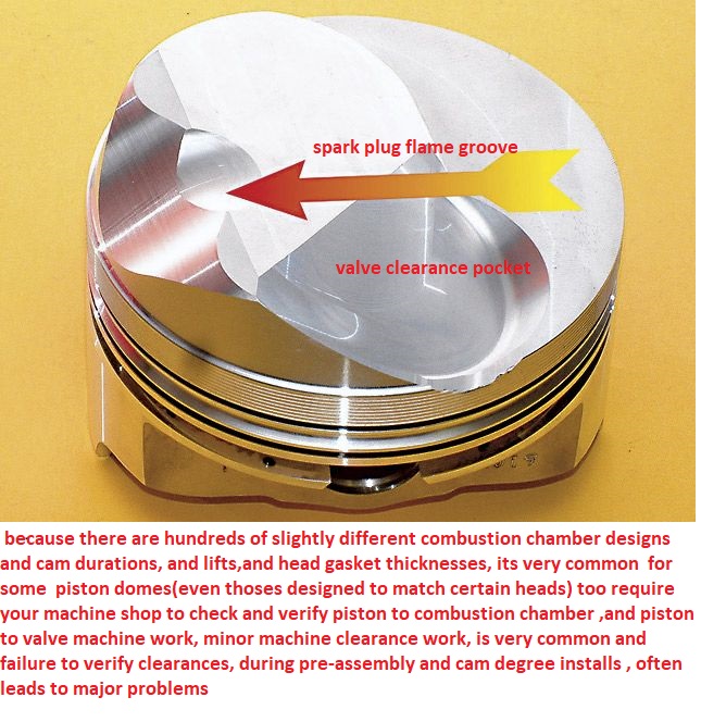
and it seldom costs much to have done.
http://www.chevyhiperformance.com/tech/ ... nce_guide/
remember at peak hp your spinning 5000rpm-7000rpm
that means that at 6000rpm, theres a power stroke 50 times a second, so theres about .004 seconds 4 thousandths of a second between the time the piston reaches 30 degrees before tdc and swings thru to 30 degrees past tdc
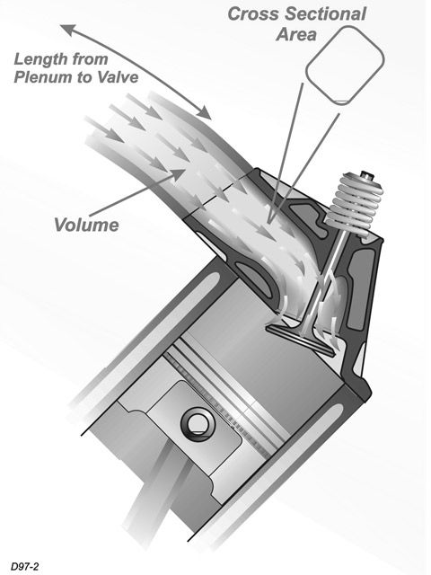
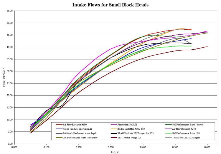
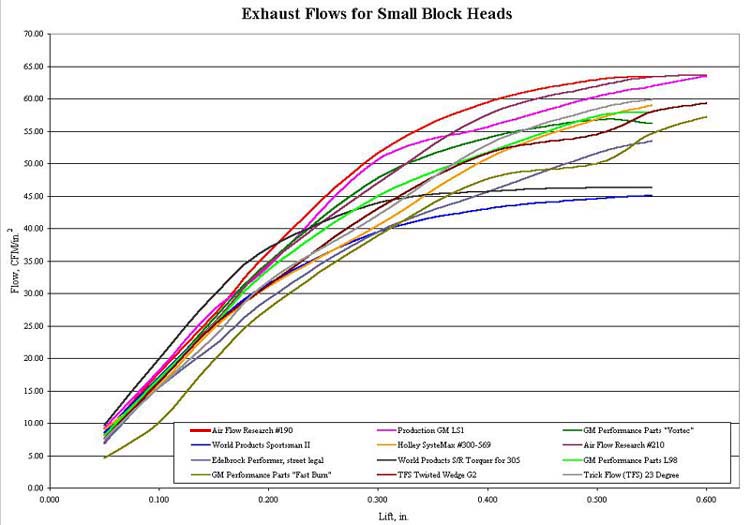
you'll generally want to built any performance engine to the maximum compression levels the fuels octane and burn characteristics will allow you to and to maximize the port flow velocity in the engine to reach about 300 fps in in port flow rates, theres links to read at the bottom of the post with more info, and look over the pictures, but remember the proper cam timing, port flow rates, and your engines header design/exhaust scavenging will also effect the engines power and those factors tend to be even more important in the 4500rpm-7500rpm range in most performance engine build ups
as most guys know your engine needs less ignition advance as the engine idles than when it starts to increase in rpm levels,because although the cylinders compressed fuel/air mix ignites and burns the time it takes for the cylinders mix to burn and produce useful pressure over the piston varies with several factors and the engine rpms are a major factor in that burn speed. ignition timing tends to go from about 8-12 degrees before top dead center to about 34-39 degrees advanced by about 3100rpm-3300, but above,about 3100-3300rpm, the rapid piston movement, and increase in several other factors like the results of squish & quench tend to increase the combustion burn speed to the point further ignition advance becomes counter productive. ignition in the cylinders may start 36-40degrees before TDC but the max pressure builds in the 24-30 degrees after TDC
the quench area basically form a jet of burning f/a mix being shot into the chamber speeding the burn,quench and SQUISH are both different concepts, but when matched correctly speed the burn and reduce the tendency for detonation.
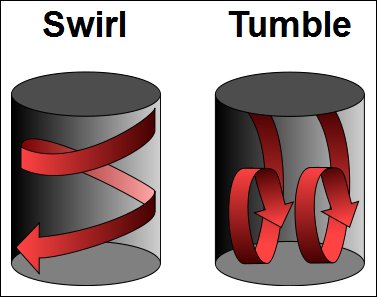
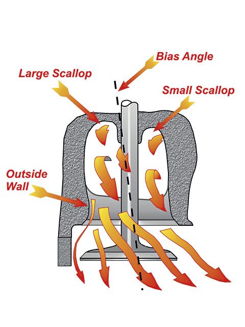
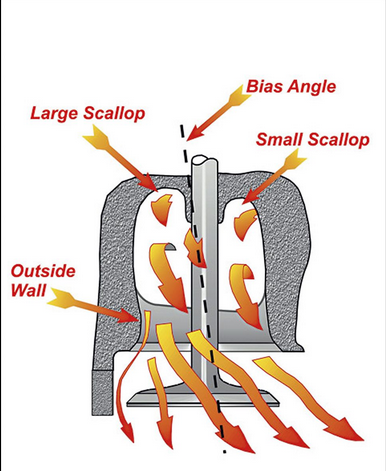
KEEP IN MIND THE BLOCKS DECK HEIGHT, PISTON PIN LOCATION, CRANK STROKE, ROD LENGTH, VALVE SIZE, VALVE SHROUDING PORT LENGTH AND CROSS SECTION AND CAM TIMING,PISTON COMPRESSION HEIGHT,AND HEAD GASKET THICKNESS,IGNITION ADVANCE CURVE, ,CYLINDER HEAD TEMPERATURE,COMBUSTION CHAMBER SURFACE SMOOTHNESS,THE MATERIAL THE HEADS ARE MADE FROM, AND HEADER SCAVENGING AND TO SOME EXTENT THE COMBUSTION CHAMBER SHAPE AND PISTON SURFACE OR DOME AND A FEW OTHER FACTORS ALL EFFECT HOW EFFECTIVE YOUR QUENCH, SWIRL AND TUMBLE WILL EFFECT YOUR ENGINES VOLUMETRIC EFFICIENCY, AND FUEL OCTANE AND ATOMIZATION, THE FLAME FRONT SPEEDS OR BURN EFFICIENCY AT ANY SELECTED RPM, SO WHILE QUENCH IS ONLY ONE FACTOR ITS GOING TO EFFECT YOUR ENGINES TENDENCY TO REACH DETONATION[/color][/b]
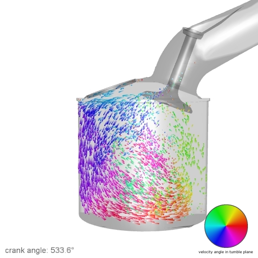
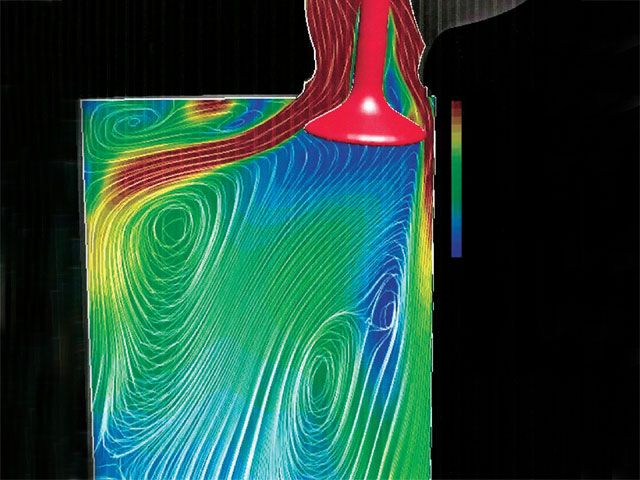
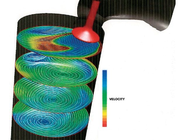
"Several prominent engine builders disagree with the need for swirl and/or tumble at engine speeds above 3-4k rpm.
mostly because the rapid flow of fuel/air mix and the rapid piston movement and heat in a running engine and the limited time available for fuel vaporization before ignition tends to lower the importance or partly reduce its effectiveness in homogenizing the mixture ratio throughout the combustion chambers, as the rapid squish and quench tend to speed up the mix and burn characteristics in the engine as the rpms increase
They (Reher-Morrison, etc.)indicate that at high rpms the fuel/air mixture becomes highly turbulent due to the squish areas of the chamber and heads with zero swirl/tumble can/do outperform heads with substantial swirl/tumble.
this has proven to be true in SOME engines while in a few the results were inconclusive at best but what seems to be consistent is that the higher the compression and the higher the engines speed the less important tumble & swirl become to the resulting PEAK POWER the engine may produce, but in almost all cases the introduction of tumble & swirl at low and mid rpms (under 3500rpm) tended to help lower emissions, and increase power and mileage)
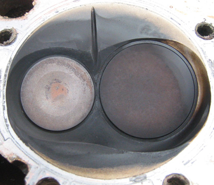
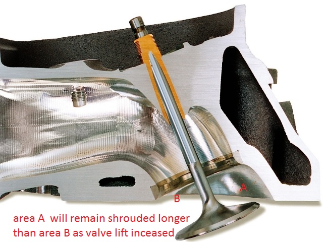
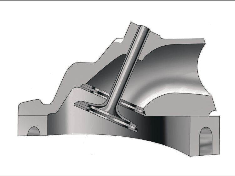
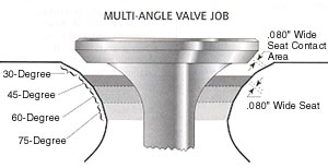
valve seat and back face angles ,valve diameter and valve lift and duration effect the flow thru the curtain area
keep in mind that valve may be forced off its seat, too full lift and re-seating 50 plus TIMES A SECOND at near 5500 rpm, so theres very little TIME for gases to move through the very restrictive space between the valve seat and valve edge
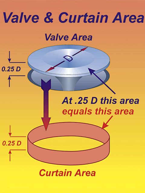
Calculating the valve curtain area
The following equation mathematically defines the available flow area for any given valve diameter and lift value:
Area = valve diameter x 0.98 x 3.14 x valve lift
Where 3.14 = pi (π)
For a typical 2.02-inch intake valve at .500-inch lift, it calculates as follows:
Area = 2.02 x 0.98 x 3.14 x 0.500 = 3.107 square inches
They do, however, agree that swirl (on 2 valve engines) and tumble (on 4 valve engines) is very important at engine speeds in the 1.5-3k rpm range when piston velocity is slower.
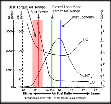
Also, engines with good combustion chamber designs/dome shape can tolerate A/F ratios in the 13.5:1 range (BSFC numbers in the 0.36 range) without detonation concerns.
Larry Widmer (Energy Dynamics, aka Endyn) was one of the first engine builders to explore the concept of swirl/tumble in the early/mid 80s. Check his website for more information.
The "craze" lasted for almost two decades. It wasn't until recently when several serious engine builders conducted detailed studies and back to back dyno test were the theories of swirl/tumble in Hi-Perf. engines proven to be wrong."
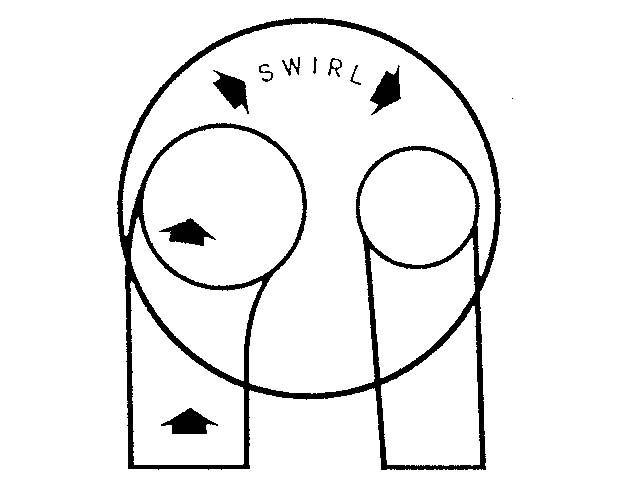
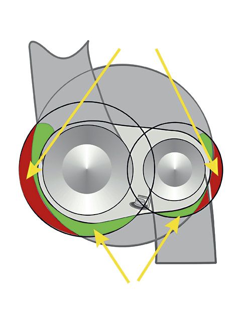
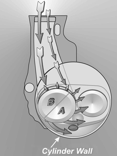
swirl

a
b
tumble

these two graphs from
http://herningg.com/projects/350heads.html
http://herningg.com/projects/350heads.html
tricks like back cuts on valves increase low rpm and low lift flow, and factors like header primary length ,collector design for increased scavenging and matching intake port cross sectional area to the intended flow rate, and cam timing are critical
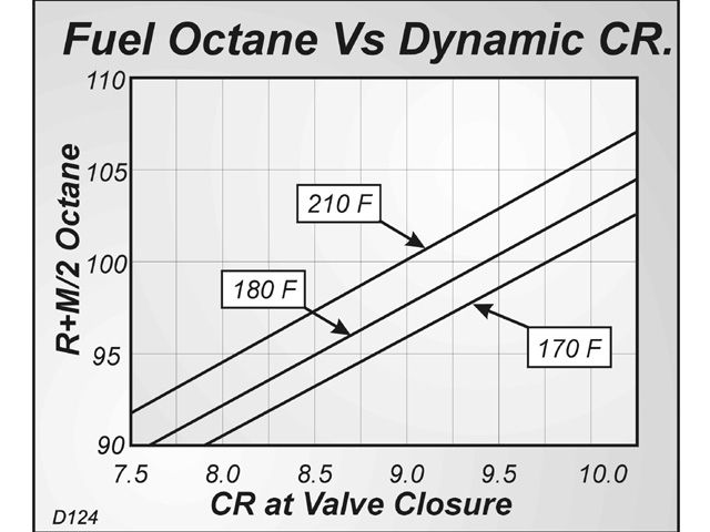
the chart pictured below is important but a bit mis-leading,
because it shows only about a 15% gain in power if you went from a 8:1 compression ratio to a 14:1 compression ratio,
in reality , you could more likely see an 15%-18% gain,
with some changes in cam timing and exhaust tuning alone,
and with other changes, 20% gains would be reasonable with that increase in compression.
so to put that in perspective, if you had a 9.5:1 compression 454 chevy,
that made lets assume 425hp, and swapped a cam and pistons,
and increased it to 12.5:1 compression .
it would be rather reasonable to expect, a gain in the range,
close to 10%, or a boost to near 470 hp once the correct octane fuel was used.
related info
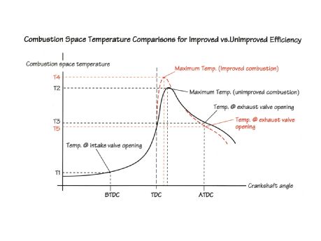
btw what your trying to accomplish is maintaining the highest pressure after tdc that you can and the lowest pressure btdc without getting into detonation with the available octane fuel
thus maximizing the pressure curve where you can effectively use that pressure
http://forum.grumpysperformance.com/viewtopic.php?f=70&t=4683
http://forum.grumpysperformance.com/viewtopic.php?f=53&t=5199&p=15129&hilit=piston+burn#p15129
http://racingarticles.com/article_racing-10.html
http://www.chevyhiperformance.com/tech/ ... index.html
http://www.contactmagazine.com/Issue54/EngineBasics.html
http://www.youtube.com/watch?v=W3qD6pYT ... re=related
http://forum.grumpysperformance.com/viewtopic.php?f=70&t=202&p=7854&hilit=flame+front#p7854
http://forum.grumpysperformance.com/viewtopic.php?f=50&t=208&p=16848&hilit=detonation#p16848
read these and sub links
http://cochise.uia.net/pkelley2/DynamicCR.html
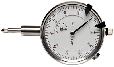
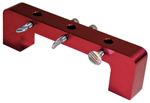
having the correct tools and learning how to use them correctly ,
can save you an enormous amount of time and effort and in many cases cash!
(obviously the tools and skills vary with the job at hand,)
so doing your research in online forums and joining a muscle car or corvette club,
where you might find a local skilled mentor to teach you skills and tools to use, helps in some cases,
it can also at times make you cash in a side job helping other car guys, or lead to a new career
Volumetric Efficiency: Is calculated by dividing the mass of air inducted into the cylinder between IVO and IVC divided by the mass of air that would fill the cylinder at atmospheric pressure (with the piston at BDC). Typical values range from 0.6 to 1.2, or 60% to 120%. Peak torque always occurs at the engine speed that produced the highest volumetric efficiency.
keep in mind as rpms increase so do port speeds and volumetric efficiency UP TO A POINT, WHERE THE TIME LIMITATION TO FILL AND SCAVENGE the cylinder limits power
viewtopic.php?f=53&t=726&p=1023&hilit=+swirl#p1023
http://www.contactmagazine.com/Issue54/EngineBasics.html
viewtopic.php?f=56&t=961
viewtopic.php?f=55&t=624
viewtopic.php?f=55&t=613&p=816#p816
viewtopic.php?f=55&t=624&p=835#p835
http://books.google.com/books?id=j8pgKX ... rs&f=false
http://www.scribd.com/doc/21485309/Comb ... ber-Design
http://www.idav.ucdavis.edu/~garth/pdfs/topoinvis05.pdf
viewtopic.php?f=70&t=1809&p=7623&hilit=+ignition+advance#p7623
http://www.eng-tips.com/viewthread.cfm? ... 46&page=47
viewtopic.php?f=53&t=3443&p=9118&hilit=+octane+calculate#p9118
viewtopic.php?f=52&t=4081&p=11104&hilit=quench+squish#p11104
viewtopic.php?f=53&t=726&p=9291&hilit=quench+squish#p9291
http://www.circletrack.com/enginetech/c ... _new_fuel/
read thru these, threads and sub links,
keep in mind theres no exact compression ratio point where detonation becomes a sure problem, while there is a compression ratio range or cylinder PSI at a known altitude, at a known air and coolant temperature,where a known octane fuel at a certain known temperature in a known combustion chamber design with a known quench and with a set surface texture or roughness , and of a known diam. and with a known spark plug design and heat range, a set distance from the cylinder center-line where its far more likely to occur, but factors as minor as the valve edge and seat diam. and ignition timing curve,the engines rpm, the effective rate of cylinder exhaust scavenging and the fuel/ air ratio and a dozen or more factors can and do effect the results.
you can easily find that two similar engines will perform quite differently due to minor differences in the engine prep, things like a few spark plug threads exposed in the combustion chamber or a sharp edge on an exhaust valve can easily swing the results noticeably.
FIRST GEN, SBC CLOYES ROLLER TIMING SET
https://www.summitracing.com/parts/clo-9-1100/overview/
MARK IV BBC CLOYES ROLLER TIMING SET 1965-90
https://www.summitracing.com/parts/clo-c-3024x/overview/
MARK VI BBC CLOYES ROLLER TIMING SET 1991-95
https://www.summitracing.com/parts/...-specific/engine-family/chevy-big-block-gen-v
theres dozens of factors that will effect your engines tendency to get into detonation.
viewtopic.php?f=71&t=1261
http://victorylibrary.com/mopar/chamber-tech-c.htm
viewtopic.php?f=53&t=726&p=9291&hilit=quench+squish#p9291
that a tighter squish/quench clearance would produce, most likely because its far easier to build and assemble engines and have fewer interference or clearance and binding issues to do so!
your engines tendency to get into detonation is the result of higher effective compression that the fuel octane your using can permit, but your piston is only compressing the fuel air mix AFTER both valves seat.detonation is a condition that occurs as the result of both cylinder temperature compressions effect on your fuel/air ratio and several other factors that cause fuel to self ignite under some conditions, lowering the EFFECTIVE compression , lowering the heat in the combustion chamber , or designing the engines quench,squish,turbulence and other factors to greatly reduce the engines tendency to get into detonation will obviously help prevent it.
TRY AND GET THE QUENCH DISTANCE BETWEEN the heads and pistons at TDC. to fall between,
as a general rule
shoot for a quench of
Minimum .045", max .060", more important is the squish area and chamber shape.
RANGE , DON'T GO INSANE IF it's ONLY POSSIBLE WITH YOUR COMPONENT CHOICES TO GET DOWN TO .050, QUENCH, its marginally less effective but still works) on most engines,the idea is to force a compressed jet of that fuel air mix, trapped between the almost contacting surfaces,(PISTON ALMOST HITTING THE HEAD) into the combustion chamber at high speed this increased turbulence increases the burn speed in the combustion chamber, and the two surfaces so close together cool the trapped gases between them ,just enough to slow or prevent detonation, reducing the distance the flame front must travel ACROSS the cylinder allows less ignition advance to be used so, mechanical EFFICIENCY to be improved
BTW When a head gasket thickness is listed its supposed to be the compressed gasket thickness ,this can be important in determining quench distance.
It might help to keep in mind, the amount of TIME the piston, is in close proximity to the cylinder head, remember the 4 cycle ,
or 720 degrees the crank turns, the the very brief time the piston spends on the power stroke, there is only about 25-40 degrees of that 720 degree cycle here theres near peak pressure above the piston, and even at idle speeds (lets assume 800 rpm) the power stoke or peak pressure , is only lets say 35 degrees in a 720 degree cycle thats happening repeatedly 13.3 times per second.
now at 7000 rpm, thats happening 58.3 times a second, think it through, about 5% of the whole 720 degree repetitive cycle
has significant torque producing pressure above the piston, exerting thrust against the crank shaft journal,
the other 95% is required just to prepare the cylinder to fire and exert that pressure pulse, theres a power pulse at each 90 degree turn of the cranks rotation, on every other time it reaches TDC.
there's about a 600-700 PSI peak pressure above the piston, that rapidly drops off as the piston descends on the power stroke as the fuel burns, expending its energy, by the time the piston reaches mid stroke pressure is reduced to far less than it was during the first 30 degrees of rotation.
if you have a 4.25" bore 454 BBC theres about 14 sq inches of piston surface are, thus about 8500 lbs or more
(depending on the F/A ratio and compression )
of force very briefly above the piston, every 90 degrees of rotation.
that pressure drops of rapidly as the piston descends down the bore and after the exhaust valve opens it drops below atmospheric pressure briefly
thinking through where the power of combustion can be Enhanced
theres a long list of factors that have to be considered and balanced for the internal combustion engine to make better power ,one major factor is the type of fuel used and the fuel/air ratio and its efficient combustion, if you want to boost power you need to more effectively increase...
garage.grumpysperformance.com
2. COMBUSTION QUALITY EVALUATION FOR SPARK IGNITION ENGINES
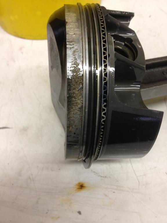
If you take the time required to understand your options and having built an engine with close to ideal quench youll find its slightly less likely to get into detonation conditions that can quickly destroy a piston, resulting in massive engine failure.
the first step is having the block decks accurately measured and if necessary machined so the block decks level and parallel with the crank center line.
in this example directly below the plugs GROUND electrode is ALMOST EXACTLY OPPOSITE, OF THE IDEAL INDEXED location , as its located wher the piston has the best chance of contacting the ground electrode,
example , now ideally youll want the ground electrode facing the roof of the combustion chamber for max clearance and flame propagation
similar too...
read the links
http://www.hotrod.com/articles/fuel-octane-rating-comparison/
http://garage.grumpysperformance.com/index.php?threads/aluminum-heads-polishing-and-porosity.14689/
if the blocks 100% correctly machined, and you get a wide variation in piston to deck heights , remember theres some variation in both piston pin height and connecting rod length, if for example you find SOME PISTONS .003 AND SOME AT 009, that MIGHT BE A RATHER HIGH VARIATION
It would indicate the block deck needs to be machined or perhaps the pistons and rods could be interchanged (longer rods, re matched with shorter piston pin heights) to get a lower average variation
you should be trying to get a .038-.044 quench height, personally I try to be on the .042-.044 range.
if the pistons sticking above the block deck your calculation subtracts the distance from the compressed head gasket thickness, if its below deck you add that distance to the head gasket thickness to arrive at the quench distance.
KEEP in mind your engines effective or dynamic compression and your effective quench distance, the materials in the cylinder head, coolant and oil temps., ,ignition advance curve,plus the engines combustion chamber temperature and fuels octane level plus several other factors determine the engines detonation threshold or tolerance, each component choice effects the complete combo[/color]
http://cochise.uia.net/pkelley2/DynamicCR.html
"Determining seat timing: Since the early days of the internal combustion gasoline engine, engineers have known that the Otto four stroke engine is compression limited and that the quality of the fuel used determines the CR at which the engine could operate. However, it is not the Static CR but the actual running CR of the engine that is important. Compression of the air/fuel mixture cannot start while the intake valve is open. It may start slightly before the intake valve is fully seated. However, there is no easy way to determine this point so using the advertised duration number provided by the cam manufacture is the next best thing. Most cam grinders use .006" of tappet lift (hydraulic cam), although some use other values, with .004" being a common one. This duration is often referred to as the "seat timing". We will used advertised duration for calculating the DCR. "
quench is basically achieved by momentarily allowing the rotation of the piston past TDC so its placing the piston and heads flat matching surfaces as the piston rotates past tdc, so close too each other that and compressed gasses and air are forced out from between the surfaces in a near collision,between the surfaces , as the rapid exiting of the compressed fuel air mix has both a cooling effect and the turbulence increases the combustion, plus heat absorbing factors and lack of space between the surfaces prevents the fuel/air mix from burning, it also reduces the distance the flame front needs to travel once ignition starts, because the SQUISH has forced much of the previously trapped fuel/air mix into the combustion chamber and away from the cylinder wall, and the increased turbulence that results, speeds the burn in that smaller combustion chamber.
squish is the rapid forced displacement of the fuel/air mix from the quench area into the smaller main combustion chamber which rapidly increases turbulence and the burn speed ,by increasing the flame front speed,much as throwing a cup of gas into a camp fire would
Any decent, experienced machine shop can measure your cylinder heads combustion chamber,
and calculate the required clearances after measuring your heads combustion chamber, and then do the correct machine work on your piston domes,
machining the domes for adequate,spark plug,clearance,
this is a very common issue and easily resolved,
and it seldom costs much to have done.
http://www.chevyhiperformance.com/tech/ ... nce_guide/
remember at peak hp your spinning 5000rpm-7000rpm
that means that at 6000rpm, theres a power stroke 50 times a second, so theres about .004 seconds 4 thousandths of a second between the time the piston reaches 30 degrees before tdc and swings thru to 30 degrees past tdc
you'll generally want to built any performance engine to the maximum compression levels the fuels octane and burn characteristics will allow you to and to maximize the port flow velocity in the engine to reach about 300 fps in in port flow rates, theres links to read at the bottom of the post with more info, and look over the pictures, but remember the proper cam timing, port flow rates, and your engines header design/exhaust scavenging will also effect the engines power and those factors tend to be even more important in the 4500rpm-7500rpm range in most performance engine build ups
as most guys know your engine needs less ignition advance as the engine idles than when it starts to increase in rpm levels,because although the cylinders compressed fuel/air mix ignites and burns the time it takes for the cylinders mix to burn and produce useful pressure over the piston varies with several factors and the engine rpms are a major factor in that burn speed. ignition timing tends to go from about 8-12 degrees before top dead center to about 34-39 degrees advanced by about 3100rpm-3300, but above,about 3100-3300rpm, the rapid piston movement, and increase in several other factors like the results of squish & quench tend to increase the combustion burn speed to the point further ignition advance becomes counter productive. ignition in the cylinders may start 36-40degrees before TDC but the max pressure builds in the 24-30 degrees after TDC
the quench area basically form a jet of burning f/a mix being shot into the chamber speeding the burn,quench and SQUISH are both different concepts, but when matched correctly speed the burn and reduce the tendency for detonation.
KEEP IN MIND THE BLOCKS DECK HEIGHT, PISTON PIN LOCATION, CRANK STROKE, ROD LENGTH, VALVE SIZE, VALVE SHROUDING PORT LENGTH AND CROSS SECTION AND CAM TIMING,PISTON COMPRESSION HEIGHT,AND HEAD GASKET THICKNESS,IGNITION ADVANCE CURVE, ,CYLINDER HEAD TEMPERATURE,COMBUSTION CHAMBER SURFACE SMOOTHNESS,THE MATERIAL THE HEADS ARE MADE FROM, AND HEADER SCAVENGING AND TO SOME EXTENT THE COMBUSTION CHAMBER SHAPE AND PISTON SURFACE OR DOME AND A FEW OTHER FACTORS ALL EFFECT HOW EFFECTIVE YOUR QUENCH, SWIRL AND TUMBLE WILL EFFECT YOUR ENGINES VOLUMETRIC EFFICIENCY, AND FUEL OCTANE AND ATOMIZATION, THE FLAME FRONT SPEEDS OR BURN EFFICIENCY AT ANY SELECTED RPM, SO WHILE QUENCH IS ONLY ONE FACTOR ITS GOING TO EFFECT YOUR ENGINES TENDENCY TO REACH DETONATION[/color][/b]
"Several prominent engine builders disagree with the need for swirl and/or tumble at engine speeds above 3-4k rpm.
mostly because the rapid flow of fuel/air mix and the rapid piston movement and heat in a running engine and the limited time available for fuel vaporization before ignition tends to lower the importance or partly reduce its effectiveness in homogenizing the mixture ratio throughout the combustion chambers, as the rapid squish and quench tend to speed up the mix and burn characteristics in the engine as the rpms increase
They (Reher-Morrison, etc.)indicate that at high rpms the fuel/air mixture becomes highly turbulent due to the squish areas of the chamber and heads with zero swirl/tumble can/do outperform heads with substantial swirl/tumble.
this has proven to be true in SOME engines while in a few the results were inconclusive at best but what seems to be consistent is that the higher the compression and the higher the engines speed the less important tumble & swirl become to the resulting PEAK POWER the engine may produce, but in almost all cases the introduction of tumble & swirl at low and mid rpms (under 3500rpm) tended to help lower emissions, and increase power and mileage)
valve seat and back face angles ,valve diameter and valve lift and duration effect the flow thru the curtain area
keep in mind that valve may be forced off its seat, too full lift and re-seating 50 plus TIMES A SECOND at near 5500 rpm, so theres very little TIME for gases to move through the very restrictive space between the valve seat and valve edge
Calculating the valve curtain area
The following equation mathematically defines the available flow area for any given valve diameter and lift value:
Area = valve diameter x 0.98 x 3.14 x valve lift
Where 3.14 = pi (π)
For a typical 2.02-inch intake valve at .500-inch lift, it calculates as follows:
Area = 2.02 x 0.98 x 3.14 x 0.500 = 3.107 square inches
They do, however, agree that swirl (on 2 valve engines) and tumble (on 4 valve engines) is very important at engine speeds in the 1.5-3k rpm range when piston velocity is slower.
Also, engines with good combustion chamber designs/dome shape can tolerate A/F ratios in the 13.5:1 range (BSFC numbers in the 0.36 range) without detonation concerns.
Larry Widmer (Energy Dynamics, aka Endyn) was one of the first engine builders to explore the concept of swirl/tumble in the early/mid 80s. Check his website for more information.
The "craze" lasted for almost two decades. It wasn't until recently when several serious engine builders conducted detailed studies and back to back dyno test were the theories of swirl/tumble in Hi-Perf. engines proven to be wrong."
swirl
a
b
tumble
these two graphs from
http://herningg.com/projects/350heads.html
http://herningg.com/projects/350heads.html
tricks like back cuts on valves increase low rpm and low lift flow, and factors like header primary length ,collector design for increased scavenging and matching intake port cross sectional area to the intended flow rate, and cam timing are critical
the chart pictured below is important but a bit mis-leading,
because it shows only about a 15% gain in power if you went from a 8:1 compression ratio to a 14:1 compression ratio,
in reality , you could more likely see an 15%-18% gain,
with some changes in cam timing and exhaust tuning alone,
and with other changes, 20% gains would be reasonable with that increase in compression.
so to put that in perspective, if you had a 9.5:1 compression 454 chevy,
that made lets assume 425hp, and swapped a cam and pistons,
and increased it to 12.5:1 compression .
it would be rather reasonable to expect, a gain in the range,
close to 10%, or a boost to near 470 hp once the correct octane fuel was used.
related info
btw what your trying to accomplish is maintaining the highest pressure after tdc that you can and the lowest pressure btdc without getting into detonation with the available octane fuel
thus maximizing the pressure curve where you can effectively use that pressure
http://forum.grumpysperformance.com/viewtopic.php?f=70&t=4683
http://forum.grumpysperformance.com/viewtopic.php?f=53&t=5199&p=15129&hilit=piston+burn#p15129
http://racingarticles.com/article_racing-10.html
http://www.chevyhiperformance.com/tech/ ... index.html
http://www.contactmagazine.com/Issue54/EngineBasics.html
http://www.youtube.com/watch?v=W3qD6pYT ... re=related
http://forum.grumpysperformance.com/viewtopic.php?f=70&t=202&p=7854&hilit=flame+front#p7854
http://forum.grumpysperformance.com/viewtopic.php?f=50&t=208&p=16848&hilit=detonation#p16848
read these and sub links
http://cochise.uia.net/pkelley2/DynamicCR.html
having the correct tools and learning how to use them correctly ,
can save you an enormous amount of time and effort and in many cases cash!
(obviously the tools and skills vary with the job at hand,)
so doing your research in online forums and joining a muscle car or corvette club,
where you might find a local skilled mentor to teach you skills and tools to use, helps in some cases,
it can also at times make you cash in a side job helping other car guys, or lead to a new career
Volumetric Efficiency: Is calculated by dividing the mass of air inducted into the cylinder between IVO and IVC divided by the mass of air that would fill the cylinder at atmospheric pressure (with the piston at BDC). Typical values range from 0.6 to 1.2, or 60% to 120%. Peak torque always occurs at the engine speed that produced the highest volumetric efficiency.
keep in mind as rpms increase so do port speeds and volumetric efficiency UP TO A POINT, WHERE THE TIME LIMITATION TO FILL AND SCAVENGE the cylinder limits power
viewtopic.php?f=53&t=726&p=1023&hilit=+swirl#p1023
http://www.contactmagazine.com/Issue54/EngineBasics.html
viewtopic.php?f=56&t=961
viewtopic.php?f=55&t=624
viewtopic.php?f=55&t=613&p=816#p816
viewtopic.php?f=55&t=624&p=835#p835
http://books.google.com/books?id=j8pgKX ... rs&f=false
http://www.scribd.com/doc/21485309/Comb ... ber-Design
http://www.idav.ucdavis.edu/~garth/pdfs/topoinvis05.pdf
viewtopic.php?f=70&t=1809&p=7623&hilit=+ignition+advance#p7623
http://www.eng-tips.com/viewthread.cfm? ... 46&page=47
viewtopic.php?f=53&t=3443&p=9118&hilit=+octane+calculate#p9118
viewtopic.php?f=52&t=4081&p=11104&hilit=quench+squish#p11104
viewtopic.php?f=53&t=726&p=9291&hilit=quench+squish#p9291
http://www.circletrack.com/enginetech/c ... _new_fuel/
read thru these, threads and sub links,
keep in mind theres no exact compression ratio point where detonation becomes a sure problem, while there is a compression ratio range or cylinder PSI at a known altitude, at a known air and coolant temperature,where a known octane fuel at a certain known temperature in a known combustion chamber design with a known quench and with a set surface texture or roughness , and of a known diam. and with a known spark plug design and heat range, a set distance from the cylinder center-line where its far more likely to occur, but factors as minor as the valve edge and seat diam. and ignition timing curve,the engines rpm, the effective rate of cylinder exhaust scavenging and the fuel/ air ratio and a dozen or more factors can and do effect the results.
you can easily find that two similar engines will perform quite differently due to minor differences in the engine prep, things like a few spark plug threads exposed in the combustion chamber or a sharp edge on an exhaust valve can easily swing the results noticeably.
FIRST GEN, SBC CLOYES ROLLER TIMING SET
https://www.summitracing.com/parts/clo-9-1100/overview/
MARK IV BBC CLOYES ROLLER TIMING SET 1965-90
https://www.summitracing.com/parts/clo-c-3024x/overview/
MARK VI BBC CLOYES ROLLER TIMING SET 1991-95
https://www.summitracing.com/parts/...-specific/engine-family/chevy-big-block-gen-v
theres dozens of factors that will effect your engines tendency to get into detonation.
viewtopic.php?f=71&t=1261
http://victorylibrary.com/mopar/chamber-tech-c.htm
thinking through where the power of combustion can be Enhanced
theres a long list of factors that have to be considered and balanced for the internal combustion engine to make better power ,one major factor is the type of fuel used and the fuel/air ratio and its efficient combustion, if you want to boost power you need to more effectively increase...
garage.grumpysperformance.com
viewtopic.php?f=53&t=726&p=9291&hilit=quench+squish#p9291
Last edited by a moderator: