Fabrication of a 200-4R Transmission Mount

Indycars

Administrator
Staff member

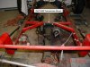
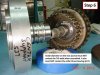
Today I decided it was time to start thinking seriously about the relocation of my
trans mount. The TBucket had a TH350 before, but now I'm building an overdrive
trans called a 200-4R. The 200-4R doesn't have a bolt on tail shaft housing, like
the TH350 did. The mounts are about 6 inch difference if you are only considering
the transmission, but in my situation the mount will have to move about 4 inches.

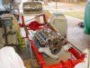
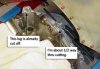
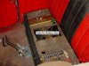
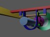
I used the an old Chevy 350 cu in block for my mock up to see how I'm going to
do this. I'm thinking about dropping down from the top like I did before, that
way when I need to pull the trans out there is nothing under it to get in the way.


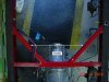
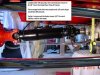
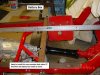
I'm considering this as a possible solution. Add new mount where the WHITE arrow
is below. Then drop down to the trans mount from there.


Attachments

  • FrontView01_3486.jpg
    FrontView01_3486.jpg
    70.8 KB · Views: 306
  • SideView01_3488.jpg
    SideView01_3488.jpg
    66.6 KB · Views: 306
  • TopView_3492.jpg
    TopView_3492.jpg
    52 KB · Views: 306
  • OldTH350Mount_0006.jpg
    OldTH350Mount_0006.jpg
    52.7 KB · Views: 306
I can see where some 2" angle iron, some careful measuring, and a chop saw and welder, would allow you to easily fabricate a easily removable trans mount
 
grumpyvette said:
I can see where some 2" angle iron, some careful measuring, and a chop saw and welder, would allow you to easily fabricate a easily removable trans mount

Are you thinking about using the framework (1"x1") that's already there or using the main rails (2"x3")??? Would it go under the trans mount?

This is my first thought was something like this.


Attachments

  • SideView01_3488.jpg
    SideView01_3488.jpg
    67.2 KB · Views: 299

Before I can make any real decisions about what the new trans mount will look
like, I needed to get the body on the frame. As I suspected the two unused mounting
lugs for the trans were going to be to high and interfere with the body.

Since they are not used, then there was no problem with cutting them off. This is
NOT the transmission case that will be used for the rebuild that I'm doing, so there
was no need to make this real pretty. Just get them out of the way. After cutting
them off I used my die grinder to cut them down some more.


Attachments

  • RemovingTransLugs03_3755.jpg
    RemovingTransLugs03_3755.jpg
    55.3 KB · Views: 262
  • RemovingTransLugs02_3754.jpg
    RemovingTransLugs02_3754.jpg
    53.3 KB · Views: 262
  • RemovingTransLugs01_3748.jpg
    RemovingTransLugs01_3748.jpg
    43.5 KB · Views: 262
Wow Rick, that is a very tight fit between the 200R4 Trans Case & the T- Bucket Body.
1964 to 1972 Pontiac GTO guys would kill to have your GM 200R4 before you cut off the 2 upper unused ears. Those 2 are meant for Buick, Olds, Pontiac V8 engines. The Overdive 200R4 is the #1 choice for Musclecar GTO owners wanting to do Hot Rod Power Tour Pro Cruising Events.
I see why you had to remove them.

BR
 

I hate to to be the bearer of bad news, but I'm going to do it again to my other trans case. The one that will actually be going in the car, I will do a much nicer and smoother job on the next case.

The 200-4R has one of the lowest parasitic loses of any OD trans. Also in its favor is the best OD for cruising the highway at .67: 1 On the down side it will not handle over about 300-350 lb*ft of torque in it's stock form. So they almost always have to be beefed up for anything other than the original power plant.


Today I put the fuel tank(Coors Beer Keg) on the chassis and filled it with 15 gallons
of water. Also in the body seating area I piled in another 210 lbs. Trying to simulate
a average loaded condition, so I can determine the drive line angle. I need to know
the distance from the top of the frame to the transmission mount. Searching Summit
I found a trans mount bushing with dimensions of 1-15/16", which would be added to
the 8-1/8" in the photos.

The angle looks pretty good thru the Trans , U-Joint, Driveshaft, U-Joint, Pinion Gear.
I'm 50 lbs off from a calculated normal load of 385 lbs. But at 1/4" per 100 lbs, I'm close
enough to normal.


I'm planning on adding to 1" x 2"cross member just behind the K member, both a trans
mount and the drive shaft loop. Hard to understand from the previous photos, but it
will become clear in the future posts.

Another reason for putting the body on the chassis is to confirm it's clearance of the
200-4R. It was fine when I had the TH350, but the bell housing part of the trans is
likely different in it's dimensions.

BTW, I did compensate for the difference in water and gasoline. I used 8.34 lbs/gal
for water and 6.0 lbs/gal for gasoline.


Attachments

  • DriveLineAngleWith330Lbs_3763.jpg
    DriveLineAngleWith330Lbs_3763.jpg
    61.6 KB · Views: 244
  • Inches8-1~8-toTopOfFrame_3773.jpg
    Inches8-1~8-toTopOfFrame_3773.jpg
    47.8 KB · Views: 244
  • RearViewOfDriveLineAngle_3772.jpg
    RearViewOfDriveLineAngle_3772.jpg
    51.6 KB · Views: 244
  • TransTouchingBody_3764.jpg
    TransTouchingBody_3764.jpg
    48.7 KB · Views: 244
  • TBucket.jpg
    TBucket.jpg
    47 KB · Views: 244
Indycars said:

I hate to to be the bearer of bad news, but I'm going to do it again to my other trans case. The one that will actually be going in the car, I will do a much nicer and smoother job on the next case.

The 200-4R has one of the lowest parasitic loses of any OD trans. Also in its favor is the best OD for cruising the highway at .67: 1 On the down side it will not handle over about 300-350 lb*ft of torque in it's stock form. So they almost always have to be beefed up for anything other than the original power plant.


:D

Someday I may want to use a 200R4 behind a Pontiac or Olds engine Rick.
But not this year, too much going on already.
Yes, I have heard very good things about 200R4's. You don't see many no more in daily drivers'. Even the GM 700R4 RWD & 4wd version has become obscure.
All Electronic Overdrive transmissions.
Most people don't even know what a TV or Throttle valve cable is anymore.
The Buick Grand National guys favor the 200R4. I understand they had a specially modified unit just for them from GM.
Caught tidbits on the internet about 200R4 Planetary gearset updates while rebuilding my 87 Vette 700R4.
I am sure your aware of them better than me.
I used NOS GM 5- Pinion Planetary Gearsets in my 700R4. Add some much needed strength for the long haul.

Does a 200 R4 use an intermediate shaft & support like a GM Turbo 400 ? It adds alot of driveline geartrain strength to an automatic trans.
700R4 & 4L60E don't have intermediate shaft & support. 4L80E trans has intermediate shaft support like Turbo 400 has.

BR
 
Indycars,As always IM simply amazed at your ability to take and post clear photos of your projects.
Ive seen several guys try and fail to post anything near as clear of pictures or guys that might have pictures they want to post but are clueless as to how to get a digital picture from a camera to the thread they choose to post it in!
YES I FULLY ADMIT I, and several other older members are being dragged kicking and screaming all the way into the age of computer use!
could you post a step by step guide for computer and camera total idiots as to how you take and post pictures now Im sure most people have access to or can get access to a digital camera, but once the pictures taken, how do you get it from the camera to posted in a thread?
remember your instructions are to be used by and your more than likely dealing with people who are totally unfamiliar with the process.
obviously a few tips on how to take clear pictures and what camera to buy, or connection cables, interface devices, software or any other related info would also help guys that may not yet have a camera , or guys who have never posted a picture they took.

YES IVE READ THRU THIS THREAD SEVERAL TIMES and while I understand much of it , there are parts that I don,t seem to understand as Im sure is true with some other members
viewtopic.php?f=25&t=4217&p=11112&hilit=posting+pictures#p11112
 
Does a 200 R4 use an intermediate shaft & support like a GM Turbo 400 ? It adds alot of driveline geartrain strength to an automatic trans. 700R4 & 4L60E don't have intermediate shaft & support. 4L80E trans has intermediate shaft support like Turbo 400 has.

Yes the 200-4R has a Center Support. Not being an expert it's hard for
me to be sure about the Intermediate Shaft, but it looks like MAYBE
they combined the Rear Sun gear and the Intermediate Shaft in 200-4R.


Attachments

  • CenterSupportToForwardDrumInterface_3477.jpg
    CenterSupportToForwardDrumInterface_3477.jpg
    57.9 KB · Views: 236
Thanks Rick.
The 200 R4 Having a Center support explains how when built up for Buick Grandnational GNX crowd, the 200R4 Trans can take over 1400 Horsepower & hold together for a 3,300 lb race weight car into the 8's 1/4 mile.

BR
 

More room is always good and I may need to install the cross member back about
another 2 inches. But for that to happen the battery box will have to move.

I'm considering using a smaller AGM battery made by Odyssey model # PC680. It
can be installed in any orientation except upside down. Lots of guy in the TBucket
world are using them. The PC680 is only 3.11 inches wide, therefore I could lay
it down under the seat right over where the battery box would have extended up
thru the floor. It's not vented so it would be safe for the electrical connections nearby.

This would free up a lot of room under the car because it would be completely
inside the body now.

These batteries are a different animal. They have a tremendous output for their
size, but over a shorter period of time. Consider the PHCA rating, it's like the HCA,
but for only 5 seconds, instead of the normal 30 second test. Most cars start within
5 seconds, especially the well maintained street rods and hot rods. It also holds a
charge much longer. Anyway you can read more about them, just use the link below.

Odyssey Battery Company
http://www.odysseybattery.com/batteries.html


Check out the electric scooter with 4 PC680 batteries, he claims it's faster than his
Vette up to 60 MPH. Most of his buddies bit the dirt trying to ride it.
See the whole story here.
http://www.tbucketeers.com/threads/fast ... ric.11986/


Here is the thread for the guys using this battery in their TBuckets.
http://www.tbucketeers.com/threads/odys ... 680.12246/


Attachments

  • BatteryBoxConflict_3744.jpg
    BatteryBoxConflict_3744.jpg
    50.8 KB · Views: 260
  • BatteryBoxConflict_3745.jpg
    BatteryBoxConflict_3745.jpg
    60.6 KB · Views: 260
  • OdysseyBatteryPoweredBike.jpg
    OdysseyBatteryPoweredBike.jpg
    66.9 KB · Views: 260
  • OdysseyBatterySpecifications.jpg
    OdysseyBatterySpecifications.jpg
    74.8 KB · Views: 260

Since I have the 3D software, I might as well use it to do some visualization of
what I'm thinking for a trans mount. I want to include with the trans mount a
driveshaft loop. Don't really want that driveshaft coming thru the floor of the
TBucket, which is possible at this time since the floor is 3/4 inch plywood. So
alittle steel between the driveshaft and my tail is a good thing.

I just moved the mount back for the loop, so I have NOT extended the vertical
component with holes forward, but I think might get the idea where I'm headed.


Attachments

  • TransMountSideView01.jpg
    TransMountSideView01.jpg
    12.3 KB · Views: 238
  • TransMountTopView01.jpg
    TransMountTopView01.jpg
    11.3 KB · Views: 238
  • TransMountPerspectiveView01.jpg
    TransMountPerspectiveView01.jpg
    11.9 KB · Views: 238

I took a day of vacation so ..... I've been working most of today on visualizing
the trans mount and driveshaft loop. My goal has been to combine them into
the same cross structure.

It wanted to make it adjustable, because it's just not possible to make exact
measurement when everything is not at 90° with each other. So the trans
mount and loop have several holes to make it adjustable.

For the important components I've tried to make reasonably accurate
measurements which are depicted in the graphics below.


Attachments

  • TransMountPerspectiveView02a.jpg
    TransMountPerspectiveView02a.jpg
    15.3 KB · Views: 231
  • TransMountPerspectiveView02c.jpg
    TransMountPerspectiveView02c.jpg
    14.3 KB · Views: 230
  • TransMountSideView02.jpg
    TransMountSideView02.jpg
    9.3 KB · Views: 230
  • TransMountTopView02.jpg
    TransMountTopView02.jpg
    9.9 KB · Views: 230
  • TransMountPerspectiveView02d.jpg
    TransMountPerspectiveView02d.jpg
    24.5 KB · Views: 230
  • TransMountPerspectiveView02b.jpg
    TransMountPerspectiveView02b.jpg
    17.6 KB · Views: 230
you never fail to keep impressing me with your skill at computer graphics and related ability with a camera :mrgreen:
 

I find it's alot easier to make mistakes in the computer, instead of on the real part
and starting over. I've backed up and made many changes, sometimes several times
to the very same piece. Can't do that on the real part and even get done.

I really need to make sure I have it right so I can give some drawings to
busterrm (Bob). He has been kind enough to offer his services and cut out
several of the pieces and then come and weld them for me using a process
called Dry Rig or Scratch Start TIG.

Since I don't need to worry about weight, I selected 3/8" plate so I can drill
and tap holes where I need to bolt it together. I'm considering putting a lock
nut on the back, so it can't come loose.

 
grumpyvette said:
(1)
could you post a step by step guide for computer and camera total idiots as to how you take and post pictures now Im sure most people have access to or can get access to a digital camera, but once the pictures taken, how do you get it from the camera to posted in a thread?
remember your instructions are to be used by and your more than likely dealing with people who are totally unfamiliar with the process.

obviously a few tips on how to take clear pictures and what camera to buy, or connection cables, interface devices, software or any other related info would also help guys that may not yet have a camera , or guys who have never posted a picture they took.

(2)
YES IVE READ THRU THIS THREAD SEVERAL TIMES and while I understand much of it , there are parts that I don,t seem to understand as Im sure is true with some other members

viewtopic.php?f=25&t=4217&p=11112&hilit=posting+pictures#p11112

(1)
You are a sneaky something ;), how long did you wait to post these questions???
The only things I see that have not been covered are...... "what camera to buy, or
connection cables, interface devices"

(2)
I'm not sure if you are referring to taking photos or the subject of the thread.....are
you suggesting something that's not been covered in my thread below???

Check out the thread below and then let me know what you think we need.

viewtopic.php?f=25&t=5595

 
I like what I see there, thats a good plan of action to incorporate both the tranny mount and the driveshaft loop from the same origin. I will await the drawings and will get to work making all the parts. I think its going to look great when its done.
 
Okay, per Indycars drawings, here is a picture of the transmission mount parts I currently have fabricated so far:
transmissionmount001.jpg

The long curved pieces mount to the permanent crossmember and make their way down to a U-bracket(not yet made) that mounts to the transmission itself. the little C shape pieces are the mounting brackets that the driveshaft loop(not yet made either) mounts to behind the cross member. the flat piece is the piece these parts will be attached to, that is suspended below the actual crossmember.
 

Those are some very very COOL looking
brackets now, even if I say so myself!!!


Many many thanks to busterrm for his help!!!
ThankYou.gif


Back
Top