TBucket 200-4R Transmission Project


Trying to get my head back in the game, I was ready about my three setup options
with the 1-2 and 3-4 accumulator valves. By just reading the manual, I should pick
the last option to get the firmest shift possible. But I wondered since most shift kits
are for cars much heavier than mine by 1500-2000 lbs, I decided to send Chris at
CK Performance an email to confirm the right option.

Luckily for me I sent that email because he suggested starting with the softest
option ....completely opposite of the the manual.

I would start with the softest settings. As for the governor we need to
know where it shifts at now and what governor you are using.


-----Original Message-----
From: rickmiller <rickmiller@cox.net>
To: trannyman0101 <trannyman0101@aol.com>
Sent: Thu, May 16, 2013 11:29 am
Subject: 24RSRK/A Shift Kit Options

Chris,

I need to confirm which option to choose for the 1-2 & 3-4 accumalator in the
200-4R trans. You recommend for anything over 325 HP to eliminate the valve
and use the 1/4" cup plugs per your instruction manual.

My car is a TBucket that only weighs about 1800 lbs and will mostly be used for
street/cruising, with the occasional blast. Should I still use 1/4" cup plugs or
drop back to the middle option from your instructions for the shift kit 24RSRK/A.


Car/Engine Specs:

Your D5 2800 RPM stall converter
Ford 9" , 3.7:1 limited slip differential
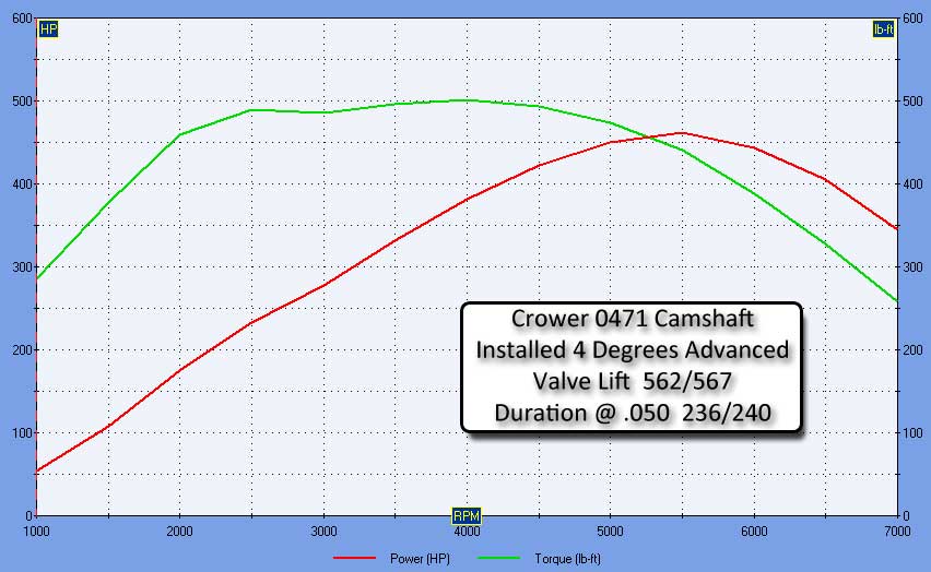
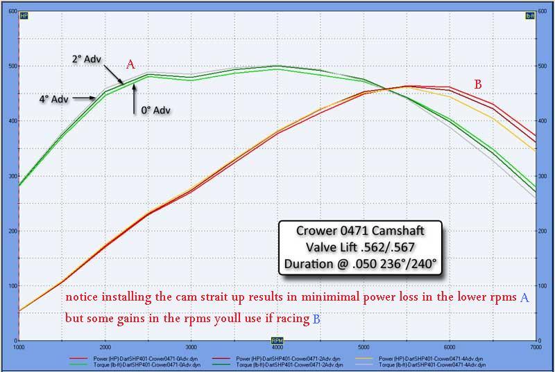
400 cuin SBC (See HP/Torque Attached)
Crower Camshaft 00471

DynoSim5_Plot.jpg

Below is the page of the manual I was reading with my options for configuring the trans.

Page13CKPerformance.jpg


Last edited:
Indycars said:

Now that I have the case painted, I've been cleaning up all the bolts on the
bench grinder/wire wheel and and few small pieces that go inside the pan.
If I'm lucky I might get started with the final assembly this weekend, but
knowing that I've never been there before it still might be a slow process.
The wife's 60th birthday is tomorrow so that might get in the way just alittle
bit. Just so you know, she married a younger man ! :)

It's not just a matter of bolting everything back together once the trans is
done. For example, the old shifter is not going to work most likely and the
throttle linkage will have to change. Most likely I will go to a cable setup there,
but again it's not just a bolt in operation for the TBucket.

Grumpy ..... I wish I could give a everyone a good guess when I'm going to
drive the TBucket, but I thought I would have been done over a year ago when
I first started this project to put the car back on the road ....sigh !!!

But your going to be in great shape when its back on the road Rick. Take pride in that!
 
DynoSim5_Plot.jpg


Im looking forward to seeing the results of this engine build in your t-bucket, Id like to hear your impression after a test drive!
IM reasonably sure youll find it rather interesting!

Now I fully realize this doesn,t really apply in this case, BUT I,ll point out here that The vast majority of people who install cams rarely take the time to degree them in correctly and simply install them using the factory timing sets index marks where the cam will usually be indexed close to 4 degrees advanced from the strait up or split over=lap location in relation to crank index. (btw I usually install cams like that strait up or split overlap or rarely 4 degrees retarded,not 4 degrees advanced, )

can you post two more dyno sim, plot curves? or even better show all three on the same chart??
engine power curve sims using the changed cam index,
that are basically similar in every respect,
but one strait up and one 4 degrees retarded for a comparison,
(kind of an instructional aid)
the reason I tend to degree in the cams in engines built like this one is, in the strait up or even retarded, indexed a few degrees retarded is that it tends to increase the AVERAGE torque curve slightly, if you think about it youll rarely be concerned with off idle or low mid rpm torque in a light car with a 3.73:1 rear gear, smoking the tires is rarely difficult with the power to weight ratio, but if your holding the gas petal on the floor, and trying to maximize the cars 1/4 mile speed, its a fair bet the upper mid range and peak power level holds some importance to your goals, far more than a few foot lbs at 2500rpm-3500rpm , that you gain by having the cam timing advanced, that retarded cam timing tends to show advantages in the 5000rpm-6500rpm power band.
your vary unlikely to notice the difference untill the cars well tuned and your familiar with the car, but after its sorted out you might

related threads

viewtopic.php?f=52&t=90

viewtopic.php?f=69&t=3814

viewtopic.php?f=52&t=1070

viewtopic.php?f=52&t=399

viewtopic.php?f=52&t=181

viewtopic.php?f=52&t=480

viewtopic.php?f=52&t=528

viewtopic.php?f=52&t=9074

viewtopic.php?f=52&t=4532

viewtopic.php?f=52&t=3745&p=9929&hilit=cam+degree+tools#p9929

viewtopic.php?f=52&t=1759&p=4441&hilit=cam+degree+tools#p4441
 
Take your time assembling the T-bucket's 200R4.
Its all about details, careful planning, good premium parts used, and reading up in the service manual & ATSG Book.
My 87 Corvette was down for 10 months. Took time to research, find premium parts I wanted, time to blueprint, & assemble.
Once built I had the 700R4 back in my car in 6 hours.
Driving later that night.
3 days later my son Nicholas was born.

Life has been busy since !!
 
87vette81big said:
Take your time assembling the T-bucket's 200R4.
Its all about details, careful planning, good premium parts used, and reading up in the service manual & ATSG Book.
Brian..... if I take anymore time, none of us will live long enough to see this car run!!! :lol: :p

 
Im looking forward to seeing the results of this engine build in your t-bucket, Id like to hear your impression after a test drive!
IM reasonably sure youll find it rather interesting!

Rick Speaking,
I'm sure my voice with be a few octaves higher after the first drive.


Now I fully realize this doesn,t really apply in this case, BUT I,ll point out here that The vast majority of people who install cams rarely take the time to degree them in correctly and simply install them using the factory timing sets index marks where the cam will usually be indexed close to 4 degrees advanced from the strait up or split over=lap location in relation to crank index. (btw I usually install cams like that strait up or split overlap or rarely 4 degrees retarded,not 4 degrees advanced, )
Rick Speaking,
I have to admit, I got lazy and didn't want to go back and change it
after I had gone thru the degreeing process at 4°advanced.


can you post two more dyno sim, plot curves? or even better show all three on the same chart??
engine power curve sims using the changed cam index,
that are basically similar in every respect,
but one strait up and one 4 degrees retarded for a comparison,
(kind of an instructional aid)

the reason I tend to degree in the cams in engines built like this one is, in the strait up or even retarded, indexed a few degrees retarded is that it tends to increase the AVERAGE torque curve slightly, if you think about it youll rarely be concerned with off idle or low mid rpm torque in a light car with a 3.73:1 rear gear, smoking the tires is rarely difficult with the power to weight ratio, but if your holding the gas petal on the floor, and trying to maximize the cars 1/4 mile speed, its a fair bet the upper mid range and peak power level holds some importance to your goals, far more than a few foot lbs at 2500rpm-3500rpm , that you gain by having the cam timing advanced, that retarded cam timing tends to show advantages in the 5000rpm-6500rpm power band.
your vary unlikely to notice the difference until the cars well tuned and your familiar with the car, but after its sorted out you might

Here you go Grumpy:


CamTimingComparison.jpg
 
Last edited:

I wanted to replace the wiring harness while into the transmission, but then I
started wondering if I need an OEM wiring harness. It's only function that I'm
aware of is to activate the converter lockup solenoid, and I'm sure that's going
to change from the OEM setup. Anyone have links to options that I might use???

Dorian should have some input on this since, the TT did not have the 200-4R originally.

WiringHarness_2736.jpg

 
Last edited:
I see a temperature or pressure switch in the lower left hand corner of your picture Rick.
Not real familar with 200R4 trans.
On my 87 Corrvette 700 R4 , torque converter lockup does not happen till coolant temp is 120 F.
Lockup is ECM activated. Otherwise all transmission functions are done hydraulic through valvebody.
Not sure of GM engineers logic why torque converter lockup only alowed 120 F and above.
I purchased a new TRANSTAR internal harness , part of TCC lockup soleniod on my car.
Cost was about $25.
Dorian should know more & be able to help out better than me here.
 

Thanks for jumping in with what you do know! That switch you pointed out
is listed in the ATSG manual as a pressure switch. Some 200-4R trans have
two switches.

 
http://www.summitracing.com/parts/bmm-70244/overview/

BMM-70244_QQ.jpg


I used this one and am VERY happy with it because you can adjust the speed it comes on and toggle it off + the wiring harness and connector are included + red light shift to green when the the lock is powered.

The only thing I might consider adding is a vacuum switch the cuts the lockup automatically when you get on the gas...
 

Thanks Dorian for the input!

I have found several possibilities, didn't know there were so many options.
 
Why not post links to several options you find it might prove to be useful to people reading the thread
 

I found six different companies that sell a torque converter lockup kit for the
200-4R, ranging in price from $90 to $195. The kits might use one to all the
components in the list below.

It would not be hard to wire my own lockup kit. A simple one could be made
from pressure switch that is already in the valve body and an adjustable vacuum
switch. Even simpler would be just a manual switch that the driver would have
to activate, but you might want to at least wire it thru the brake light switch.
One will need to consider ALL the ramifications of how you build your system,
for example……. If you don’t wire a brake light switch in the system, then an
emergency stop could kill the engine.

Cruise Control Switch
Manual Override for 2-4 gear
Vacuum Delay Switch
Vacuum Switch in TCC Wiring (Adjustable)
Brake Light Switch
Electronic Controlled
LED Indicator

Any way here are some of the resources that I found:

B&M
http://www.summitracing.com/parts/bmm-70244/overview/
BMM-70244_QQ.jpg

Bowtie Overdrive (BTO)
http://www.700r4.com/tech/tc_article/
http://bowtieoverdrives.com/catalog/cat ... &CATID=OA2
http://www.bowtieoverdrives.com/catalog ... ITEMID=339
BowtieOverdriveLockupKit.JPG

Monster Transmissions
http://www.monstertrans.com/store/produ ... p-Kit.html
MonsterLockupKit.jpg

Painless Wiring
http://www.summitracing.com/parts/prf-60110/overview/
Painless Lockup Kit 60110.jpg


Ron Francis Wiring
http://www.ronfrancis.com/prodinfo.asp?number=TC-75
RonFrancisTC-75.jpg

TCI
http://www.summitracing.com/parts/tci-376600/overview/
TCI-376600.jpg


Building your own system, then these components might be useful.


Standard Motor Products
http://www.summitracing.com/parts/SMP-VX3/
http://www.ebay.com/itm/Standard-Motor- ... 2c64b0e13f
VacuumSwitchSMP_VX2_01.JPG

The vacuum delay switch can be pretty expensive at around $40. GM used
it on these vehicle, so you might find one at the salvage yard for a few bucks.
GM #14014519
BUICK 87-81
CHEVROLET 87-79
GM LIGHT TRUCKS 87-80
OLDSMOBILE 87-81
PONTIAC 87-80

Stewart Warner
http://www.summitracing.com/parts/SWW-77343-04/

Superior Transmission Products
http://www.superior-transmission.com/Pr ... cfm?ID=186
Superior K058 Adjustable Vacuum Switch.jpg

Electrical Supplies
http://theelectricaldepot.com/index.php ... ex&cPath=1
http://www.clipsandfasteners.com/O_E_M_ ... _s/259.htm
https://www.pegasusautoracing.com/group ... upID=WIRE1
https://www.pegasusautoracing.com/advca ... NITIONELEC
http://terminalsupplyco.com/default.aspx


For an in-depth article written by Mike Rowand use the link below:
viewtopic.php?f=71&t=9239


Attachments

  • Painless 60110 Instructions.pdf
    362.4 KB · Views: 4
  • Lockup Kit TCI 376600.pdf
    171.5 KB · Views: 5
Last edited:

Got back from vacation, I didn't think it was going to come soon enough!!!

Had to build a another tool to support the output shaft until I can assemble
the trans far enough to hold it in place, see pic below. Actually it was a practice
piece that "Busterrm" used before he started the welding on the transmission
mount. Drilled three holes in the piece, one of which is threaded with 5/16-24
to make it adjustable as you will see it needs to be in the following pics.

OutputShaftSupport_4152.jpg

In the pics below the "Parking Paw" should be centered with the "ID 664". The
camera is slightly off to the side making it look like the two pieces are not
centered very well.

ParkingPawAlignment_4158.jpg

Looking at the inside of the trans this is what it looks like.

CenterSectionAssembly_4159.jpg

 
Last edited:

In the photo directly above, only the first steel is installed for the Lo/Reverse
clutch. There are 7 steels and 6 friction disks (ID 655) that make up this clutch.
On top of the last steel is a wave plate (ID 654), which is a type of spring that is
used thru out the transmission. Then finally the thin snap ring (ID 647) is installed.

AssemblyUpToFirstSnapRing_4161.jpg

The steel plates of the Lo/Reverse clutch have two teeth missing, they
are orientated to the top and bottom of the case.

SteelPlatesLoReverseClutch_3452.jpg
InternalComponents01.jpg

Finally on on my way to getting this trans done!!!

 
Last edited:
wow! as always great picture and info!
Im looking forward to seeing the results and seeing the car driven!
 
grumpyvette said:
wow! as always great picture and info!

Thanks Grumpy !!!

I'm looking forward to seeing the results and seeing the car driven!

That's makes two of us. :)
 

Another way to tell if you have the output shaft support adjusted properly is
to look from the pan side to see if there is any spline showing. Just a little thou.


OutputShaftSupportAdjustment_4162.jpg
 
Last edited:
Back
Top