TBucket Engine Project (Dart SHP)

I agree with Dorian, your thread is chalk full of superb engine building information. I applaud you in not only your skills as a engine builder but also your ability to share not only your words but also documenting it in illustrations of photos and charts. I have been following your thread since I joined Grumpy's site and I look forward to reading each and every single one of your posts. It gives me new and improved ideas to incorporate in what I do with my projects.
 

Is this what you are saying?

So the sealer would push up thru the expanded metal to seal against the one piece pan gasket?

WindageTraySealing.jpg

EDIT: I just realize that there would be a clearance problem by running the windage tray all the way up to the pan rails......right ? If there are clearance problems with the rods as they go by the block that grinding sometimes is a must and some oil pans will contact the rods. Then I would assume that there is not enough room for a windage tray.
 
Last edited:

Dorian, Grumpy & Busterrm

I'm truly touched by such kind words !!! :)

Sometimes I thought my posts were being perceived as just showing off, but I can see now that's not true. I probably could have been done building the engine weeks ago, but I enjoy so much, sharing the process that I wouldn't have it any other way !!!

Thanks guys, now that's enough of the touchy feely stuff, lets get back to working on our projects.
 

I was checking out the very small taper that the machine shop puts at the top of the
cylinder after they are done boring the block. Looks like it got hit by something on the
edge pushing some material into the bore. It's not deep enough that the rings would
run across this surface when it's running, but when installing the rings and pistons it
might be a problem.

Buldge01_2291.jpg

Upon looking closer with my eye loupe 8x magnification you can see how much rougher
it is than the cylinder. I was concerned that the rings would receive some scratches
as they slide into the cylinder during installation. So I used a 1/2 inch wood dowel rod
and some 1000 grit wet-or-dry sandpaper and WD40 to polish the edge.

PolishEdge01_2311.jpg
PolishEdge02_2312.jpg
TaperedSurface01_2297.jpg
TaperedSurface02_2308.jpg

Looks like I got something to do now before I can clean the block for final assembly.
.
 
Last edited:
Indycars said:

I was checking out the very small taper that the machine shop puts at the top of the
cylinder after they are done boring the block. Looks like it got hit by something on the
edge pushing some material into the bore. It's not deep enough that the rings would
run across this surface when it's running, but when installing the rings and pistons it
might be a problem.

I had the same issue. Did your sandpaper dowel trick and cleaned up edges of all the cylinders. What a difference it made test installing the pistons. I'm sure it will make ring installation easer also. Thanks for posting the tip..
 
bytor said:
I had the same issue. Did your sandpaper dowel trick and cleaned up edges of all the cylinders. What a difference it made test installing the pistons. I'm sure it will make ring installation easer also. Thanks for posting the tip..
It was moving too slow, so I tried some of my abrasives on the die grinder. This rubberized abrasive wheel did the trick. Again working the edge at several angles. Then I would use the 1000 grit paper on the dowel rod for a few minutes.


Attachments

  • RubberizedAbrasiveWheel_2316.jpg
    RubberizedAbrasiveWheel_2316.jpg
    35.4 KB · Views: 45
AHH! power die grinders! boy, have I got stories....they can be a huge help, and be a huge time saver, or a quick way to ruin parts, mostly depending on your skill level and experience.
 
grumpyvette said:
AHH! power die grinders! boy, have I got stories....they can be a huge help, and be a huge time saver, or a quick way to ruin parts, mostly depending on your skill level and experience.
Yes they can take material very fast or when that cartridge roll came apart on me and bent the arbor in heart beat. That will get your attention. :shock:

As far as the taper at the top of the cylinder, I never pushed down, just the weight of the grinder is all.
 

Since I'm replacing cam bearings again after I damaged them and will be installing them
myself, I have the chance to change the clock position of the oil hole if I want.

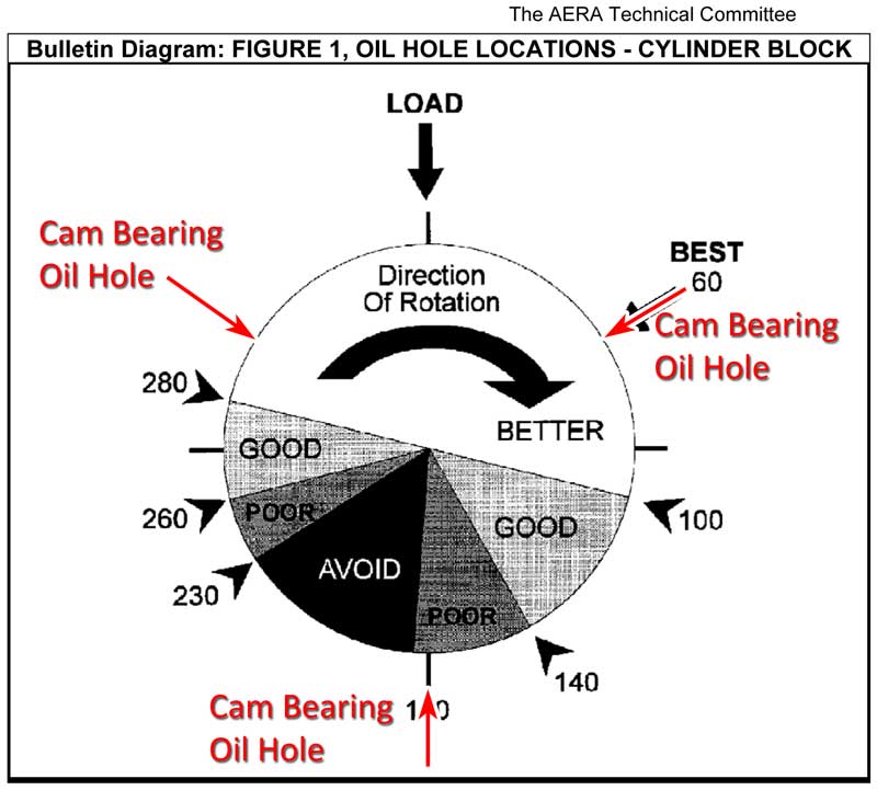
According to the diagram below, the hole should be at the 2 o'clock position, but my bearings
(DuraBond DT-1T) have a circumferential groove and 3 holes. Do I want the hole at 6 o'clock
to line up with the oil flow coming from the mains. Could the hydrodynamic lubrication
pressure be higher than the oil pressure in the block and feed backwards momentarily?

Maybe I should install them at 3 or 4 o'clock position???

Note: The Dart SHP block has "Priority Main Oiling", the oil goes to the mains first and
then to the rest of the engine.

http://www.mellingdurabond.com/Portals/ ... lletin.pdf
http://www.mellingdurabond.com/Portals/ ... arings.PDF

CamBearingClockPositionDiagram.jpg
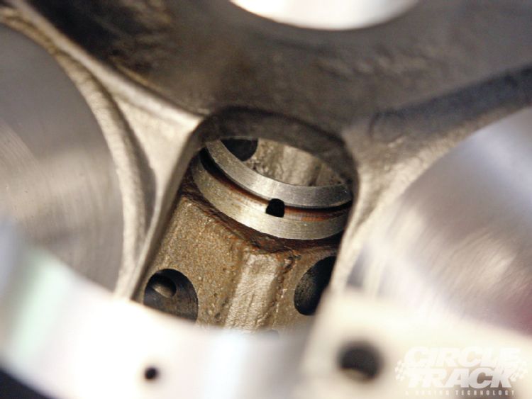
CamBearingOilHoles_2322.jpg
 
Last edited:
file.php

with the block in its normal operational position
any oil needed will easily travel thru the passages and grooves,on the back side of the cam bearing, obviously if theres no oil groove in the rear of the bearing shell or block you have zero choice but to align the oil feed to the cam bearing oil feed holes. I would keep the bearing feed holes as previously indicated if these a oil feed groove.
many cam bearings and many blocks are grooved to provide oil flow to the bearing feed holes,
direction of the feed flow to the bearing is less important than maintaining the oil wedge under the cam journal at the area of max loads


REMEMBER the pressure in any portion of an hydraulic system is equal throughout that system., your oil pump will maintain pressure and oil flow to the bearings, changing the flow direction of the oil feed passages has little effect
(oil pan at the 6 0,clock location)
place the cam bearings in the blocks cam bore exactly like the picture shows
the groove on the back helps to eliminate the total loss of oil reaching the cam journals if it is indexed into the block incorrectly, but having the oil flow enter at the top 1/3rd of the rotation provides the best possible hydraulic oil film. load support
CamBearingClockPositionDiagram.jpg


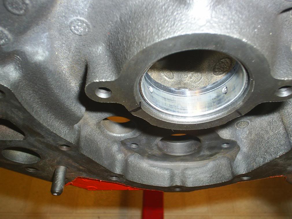
heres the block with the oil pan mounting surface at 12 o,clock or upside down, look at the correctly located oil feed holes in the cam bearings, notice they match the diagram, and two red arrows that show where the dual oil feed holes should be, on bearings with only one feed hole the 12 o,clock to 2 o,clock oil feed hole index is correct, the load is mostly on the cam bearings lower 180 degrees so you sure don,t want oil film strength lowered in that area, by having a oil feed hole that can act like an oil pressure release point in some conditions, you want a maximum thickness oil wedge formed under and supporting the cam journal
012-3.jpg
 

Since the Dart block has the oil flow going to the mains first and then up to the camshaft, the oil arrives in the worst possible location at 6 o'clock position. This is what prompted my question, since the diagrams does not address this situation.

So you think some of the oil will travel around the bearing on the outside and come in at the 2 o'clock position?
 
Wont the cam oiling come from the oil gallery?
Am not surei understand so am gonna wait for an answer me too, just curious :D
 
any oil needed will easily travel thru the passages and grooves,on the back side of the cam bearing, obviously if theres no oil groove in the rear of the bearing shell or block you have zero choice but to align the oil feed to the cam bearing oil feed holes. I would keep the bearing feed holes as previously indicated if these a oil feed groove.
many cam bearings and many blocks are grooved to provide oil flow to the bearing feed holes,
direction of the feed flow to the bearing is less important than maintaining the oil wedge under the cam journal at the area of max loads


REMEMBER the pressure in any portion of an hydraulic system is equal throughout that system., your oil pump will maintain pressure and oil flow to the bearings, changing the flow direction of the oil feed passages has little effect
oil-gallery-groove.jpg
 
mathd said:
Wont the cam oiling come from the oil gallery?
Am not sure I understand so am gonna wait for an answer me too, just curious :D
You would be correct if it was an OEM block, but I have the Dart SHP block. It's different in
that the oil goes to the oil galley, then the mains and up to the cam bearings.

OilFlowDirection.jpg
 
Last edited:

I removed all the cam bearings, including the two that I messed up earlier. Did the final wash on
the block, much easier now that 3/4 of it is painted and I don't have to worry about it rusting
except for the machined surfaces.

I put WD40 on all machined surfaces before I even started washing. The water just rolls off for
awhile, buying you some time. For the cylinders I would wash one and re-coat with WD40
immediately, then move on to the next cylinder.

The next day it was time to install the new cam bearings. The back one was alittle harder in that
you couldn't look thru the oil passage for alignment with the block upside down like I did for all
the others. I got alittle ahead of myself by installing the rear bearing and then realizing that I
wanted to chamfer the oil holes like you see below.

SideBySideComparison01_2323.jpg
UntouchedBearingCloseup01_2327.jpg
ChamferedBearingCloseup01_2330.jpg
ChamferID01_2331.jpg

This is what I used to chamfer the bearings. On the OD I used a drill, but the inside only required
a few twists by hand. The actual bearing material is very soft.

ChamferBit01.jpg

This is what the setup looked like, except when installing the rear bearing the rod was not long
enough to leave the alignment arbor on. Not really a problem since the entire length of the cam
tunnel helps you keep it straight.

BTW, you will need a small sledge hammer, a regular ball peen hammer is not heavy enough.

Overview_2339.jpg

To get the driving arbor in place you need to turn it sideways to get it into the cam tunnel.

CamTunnel_2350.jpg

Take your time here, once you start driving the bearing in, there is no going back.

LineupBearingInBlock01_2335.jpg


PERFECT !!!

CheckingAlignment_2345.jpg

I found that while driving the bearings in, it was leaving metal shavings. I used my telescoping
magnet and placed it near the bearing as I was driving it in. Afterwards I passed it over the
area around that bearing to get any remaining metal.

Look at this metal shaving that I found. At first I thought it was a brush hair.

MetalShaving_2351.jpg

If I had know it was really this easy and the tools on cost $35 for (SBC only), I would have done
it myself the first time. Would have been alot easier that loading the block up and taking it to
the machine shop.
 
Last edited:
as always the photos are amazing, thank you for posting what is an excellent educational tool,and yes installing cam bearings with the correct tool is rather easily done.
 
Me and a buddy did the cam bearing install thing with his sbc and we got the same shaving on each bearing. I would say that is normal wouldn't you agree Grumpy? Depending on the material of the bearings, I think its when the bearing is centering itself in the bore and its off just a skosh off and it shaves off the edge of the outside edge of the bearing.
 
its very common to find shavings from the cam bearings after forcing the cam bearings in place in the block.
its not required but using a dremel tool with a flap sanding wheel, to grind a minor SMOOTH 1/32" bevel on the front of the cam journal in the block, and remove burrs , and oiling the cam bearing before the install, to smooth the transition as its forced into place helps reduce this, most guys and shops don,t bother, because most cam bearings are slightly beveled on the back and front edge

dremel1.jpg

dremel2.jpg
 
Back
Top