You are using an out of date browser. It may not display this or other websites correctly.
You should upgrade or use an alternative browser.
You should upgrade or use an alternative browser.
TBucket Engine Project (Dart SHP)
- Thread starter Indycars
- Start date
Your take on this is pretty close to mine, but it does differ in that I don't think the mains have anything to do with this. One thing I didn't mention was that I turned the engine over a couple of revs before taking a reading. To get a reading I had to go thru several more revs, it was hard to read while turning and trying to do it at constant rate.busterrm said:I would be willing to say that the different increases to turn the crank has something to do with the location of the piston just put in and the pistons already in the block. For instance, #1 put in gave 65 in/lbs then #2 gave 10 more, then it took 50 more with #3 then 25 more with #4. My point is with #1 and 2 your pulling 2 mains and 2 rods, then #3 and 4 your pulling 3 mains and 4 rods. Then you move to another set, by this time you have turned it some and the lube is getting spread around all the rods and mains, so #5 doesn't affect it zilch, then # 6 bridges it to next main and adds 50 more, now your pulling 6 rods and 4 mains. Now you go to the last rod journal, # 7 adds 25 more then # 8 adds nothing, but by this time your turning real well pulling 8 rods and 5 mains. With 225 in/lbs your pulling 28.125 in/lbs or 2.344 ft/lbs per piston. I agree with Grumpy 18-20 ft/lbs is a good number for rotating assembly rotation. I am wondering what it will add when your cam has been degreed in?
The peak torque happened when the crankshaft was at about 90 & 270 degrees for that cylinder. So as I added more pistons to the mix, they were peaking at different places and therefore the torque did not always change by 65 in/lbs.
This is somewhat counter to what I know about friction. There are basically two types, static and dynamic friction. Static is typically higher and dynamic or when an object is moving does NOT change with the object velocity. So I need to look for another reason.
The other factor in all this is the leverage of the crank throw. When the crank throw is at TDC & BDC, the crank has the most leverage. When it moves thru area of 90 & 270 degrees then the leverage is reduced and therefore the reason for the additional torque required to keep the crankshaft turning.
That's my take on this.

Last edited:
The head are the Brodix IK200. The manifold is Edelbrock Performer RPM Air-Gap and the carb is undecided, but it will be a 750 cfm Quick Fuel or Speed Demon.busterrm said:Rick, this a nice looking shortblock! What are your heads? I forget! And what intake and Carb are you going to run on this beast?
http://www.summitracing.com/parts/EDL-7501/

Last edited:
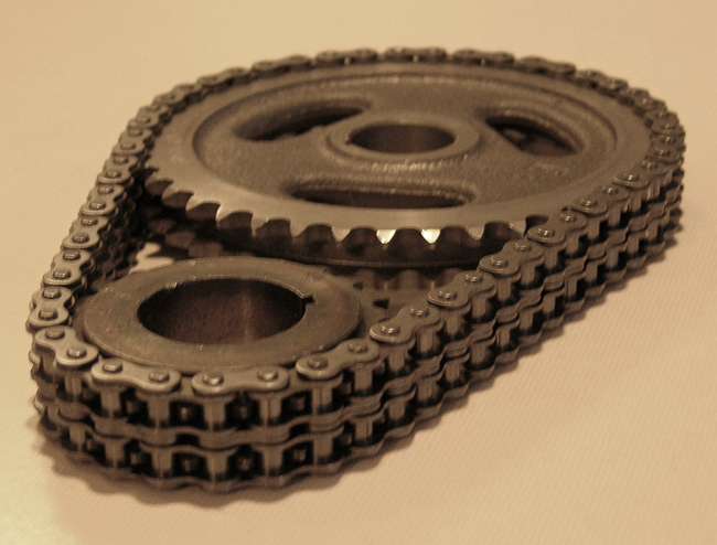
I posted the first picture back in November showing the mis-alignment between the cam
gear and crank gear. Thought I had it covered, since I ordered shim months ago in .015"
and .005" with a 1-1/4" ID to fit the crank snout. But the thing I didn't consider was the
radius, so it looks like I need to order shims with a 1-3/8 ID. It will make the OD bigger of
course but it still fits in the crank gear recess.
The Fastenal website doesn't show them in stock locally, so most likely it will be 2-3 days
before I have them in hand.


Last edited:
While getting the two gears perfectly aligned is a good idea, Id point out that theres far more flex in the chain than required to self compensate for that minimal miss alignment between the two gears.
related threads
viewtopic.php?f=52&t=90
viewtopic.php?f=52&t=181
viewtopic.php?f=52&t=5734&p=17492&hilit=timing+gear+moly#p17492
viewtopic.php?f=52&t=1793&p=4553&hilit=cam+nylon+button#p4553
viewtopic.php?f=54&t=2187
related threads
viewtopic.php?f=52&t=90
viewtopic.php?f=52&t=181
viewtopic.php?f=52&t=5734&p=17492&hilit=timing+gear+moly#p17492
viewtopic.php?f=52&t=1793&p=4553&hilit=cam+nylon+button#p4553
viewtopic.php?f=54&t=2187
busterrm
solid fixture here in the forum
I remember not many posts ago you had the freeze plug in the back of the cam didn't you say it was deeper than you wanted it? Or I maybe confused about which sprocket is out more from the block. But it looks to me like the cam is out, just thought it might be that freeze plug in to far, as you said in that post.Indycars said:
I posted the first picture back in November showing the mis-alignment between the cam
gear and crank gear. Thought I had it covered, since I ordered shim months ago in .015"
and .005" with a 1-1/4" ID to fit the crank snout. But the thing I didn't consider was the
radius, so it looks like I need to order shims with a 1-3/8 ID. It will make the OD bigger of
course but it still fits in the crank gear recess.
The Fastenal website doesn't show them in stock locally, so most likely it will be 2-3 days
before I have them in hand.
busterrm
solid fixture here in the forum
I agree about the torque increasing at 90 and 270, I wondered about it when I was building the SBC in my nova. Not sure if it matters, once I got my shortblock together, I dropped an old distributor in and spun it with a 1/2 inch impact. Oh, and the freeze plug was just something that crossed my mind due to it being just short time ago in your posts. Glad it's not that, too far in might cause the cam to wear a hole in that freeze plug.
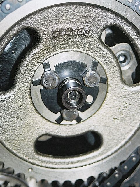
Ok I was determined to solve my problem with crank to cam gear alignment before the
weekend. I called Graingers, Fastenal, Motion Industries, MSC Supply, KP Supply and
Kamen, but none of them had or could get by tomorrow what I needed in an arbor shim
with a 1-3/8" ID. Besides it would cost me between $15-$25.
So this is what I came up with....modify what I have by using tin snip to cut several small
reliefs in the ID!!!
I wanted to be absolutely sure that the crankshaft gear didn't wobble so I checked the
runout. There is a recess in crankshaft gear that I don't have a picture of. For the crankshaft
gear to butt up against the crankshaft shoulder, there is a recess in the crankshaft gear to
allow it to seat solidly against the shoulder, but not bind up on the radius.
Since I'm measuring close to the center of rotation, there can't be much error, but I think I'm
OK and plan to use it as shown.
I started with a .024" offset, now I have a .010" offset in gear alignment. I will say that
measuring accurately is not going to happen with a scale and feeler gauges, but it's better
than NOT measuring and better than what I started with.


Last edited:
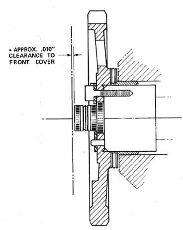
After installing the cam gear, I checked the camshaft end play again. It was .004" during
pre-assembly checking. Now I had zero and was concerned that I might have installed
the rear cam plug too far.
I suspected that it was the assembly lube that was taking up the space, but how can I
tell without removing the cam plug. It would be a real bitch to remove the cam plug, since
I can't lift the engine now. It would have to wait until I was installing the engine in the
car and had it on the engine crane.
That was yesterday, but today it hit me how I can tell and it would be very easy. Loosen
the cam gear and see how far it moves back, simple right. (Slapping forehead....you idiot!
 )
) I could see I had plenty of clearance by just looking at the dowel pin, but I needed to measure
it some how.
I used the cam bolts, they are 5/16-18 or 18 threads per inch. I tighten the bolts until
they just touched the gear with the cam pushed all the way to the back. Then I counted
the turns until it pulled the cam and gear together......7/8 of a turn. Basically I'm using the
bolts as a micrometer.
One turn would be 1/18 = .0555".....therefore
7/8(.875) / 18 = .049" of clearance. ( From camshaft to rear cam plug)
Yeah I have absolutely NO PROBLEM!!! And I didn't have to back up and remove
and re-install the cam plug.

Onward and upward !!!!!!!!!!!
Last edited:

Its up to you, I generally clean them with a scotch-brite pad,clean carefully with a clean solvent lint free rag and compressed air, spray both surfaces with copper coat spray and install them damp then torque the heads into place with sealant on the head studs threads .
when installing a copper head gasket be sure to put on one or two wet even coats on both sides of the head gasket and install and torque while the copper coat sprays still damp
good info to read thru
viewtopic.php?f=52&t=1074&p=2072&hilit=copper+coat#p2072
viewtopic.php?f=51&t=3208&p=8539&hilit=anode#p8539
viewtopic.php?f=50&t=342&p=418&hilit=torque+wrench#p418
viewtopic.php?f=50&t=1859&p=17369&hilit=threads+sealant#p17369
Not much has changed lately, but I have been busy cleaning and getting ready to install the heads.
I would have continued with timing chain and gears, but I'm waiting on a cam bolt lock plate
and new timing cover. It's in the same order as the the Proform two piece valve covers. Should
be here Tuesday.
I'm NOT sure MathD can handle this kind of engine porn, but really......who cares if he can !


I would have continued with timing chain and gears, but I'm waiting on a cam bolt lock plate
and new timing cover. It's in the same order as the the Proform two piece valve covers. Should
be here Tuesday.
I'm NOT sure MathD can handle this kind of engine porn, but really......who cares if he can !
Last edited:
It's nice and safe all wrapped up and packed away in a box. I'm using this cheaper pan for now that I bought, but decided not to use. I may even put the motor in the car before I replace the oil pan with the nice black one. The only sealer will be between the gasket and the block, but none between the gasket and the oil pan.busterrm said:hey what happened to that pretty black oil pan?
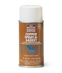
I was changing the hold I had on the head gasket and I dropped it, but I caught it before it fell over on the ground. To put it another way, it fell standing up and I caught it before it fell flat on the ground. I bent the gasket pretty good, but mainly just around the one cylinder. I straightened it by hand alittle and then put it on the block. It has two coats of the Permatex "Copper Spray-A-Gasket" #80697
I torqued the head bolts in 4 stages 20, 35, 55 and 70 ft/lbs.
What do you think, will I be OK??????????
Several of the head bolts did NOT torque smoothly. Can I loosen the head bolts and retorque them again or will that mess up the copper spray sealer?????


I torqued the head bolts in 4 stages 20, 35, 55 and 70 ft/lbs.
What do you think, will I be OK??????????
Several of the head bolts did NOT torque smoothly. Can I loosen the head bolts and retorque them again or will that mess up the copper spray sealer?????
Last edited:
"Several of the head bolts did NOT torque smoothly. Can I loosen the head bolts and re-torque them again or will that mess up the copper spray sealer?????"
you can, loosen the head bolts one at a time and then re-torque to the 55lb and 70 lb values, that should cause no major issues if done within 6-10 hours. and ID point out that bending a copper head gasket slightly is hardly a unique experience, I would not be overly concerned, thats one of the reasons they work well, they are rather pliable, in fact you can re-use copper head gaskets after cleaning and careful inspection 2-3 times with new copper coat added.
just some info for future builds
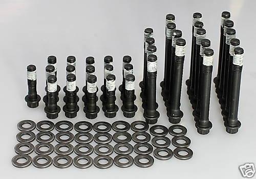
aluminum heads ALWAYS require head bolt washers with oil or ultra lube to get consistent clamp values and the flat surface faces the head the inner bevel faces the bolt head
on head STUDS the same things required on aluminum heads to get even clamp loads and no galling
unlike a OEM block DARTS blocks have blind threaded head bolt holes that don,t enter the water jacket so you need to be sure the threads are clean, theres no crud in the threaded holes and you use minimal thread sealant on the lower threads because theres little chance off coolant leaking up thru the threads like with an OEM block where head bolts enter the coolant passages
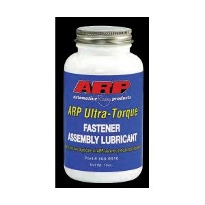
this should be used only in head bolt holes that don,t enter water jackets in the block on the lower threads

viewtopic.php?f=50&t=50&p=12558&hilit=threads+lube+torque#p12558
http://arp-bolts.com/pages/technical_installation.shtml
viewtopic.php?f=50&t=50&p=59&hilit=studs+heads+bolts+lube#p59
you can, loosen the head bolts one at a time and then re-torque to the 55lb and 70 lb values, that should cause no major issues if done within 6-10 hours. and ID point out that bending a copper head gasket slightly is hardly a unique experience, I would not be overly concerned, thats one of the reasons they work well, they are rather pliable, in fact you can re-use copper head gaskets after cleaning and careful inspection 2-3 times with new copper coat added.
just some info for future builds
aluminum heads ALWAYS require head bolt washers with oil or ultra lube to get consistent clamp values and the flat surface faces the head the inner bevel faces the bolt head
on head STUDS the same things required on aluminum heads to get even clamp loads and no galling
unlike a OEM block DARTS blocks have blind threaded head bolt holes that don,t enter the water jacket so you need to be sure the threads are clean, theres no crud in the threaded holes and you use minimal thread sealant on the lower threads because theres little chance off coolant leaking up thru the threads like with an OEM block where head bolts enter the coolant passages
this should be used only in head bolt holes that don,t enter water jackets in the block on the lower threads
viewtopic.php?f=50&t=50&p=12558&hilit=threads+lube+torque#p12558
http://arp-bolts.com/pages/technical_installation.shtml
viewtopic.php?f=50&t=50&p=59&hilit=studs+heads+bolts+lube#p59