TBucket Engine Project (Dart SHP)

With the engine out I was now able to measure the motor mount holes in the
frame at 19.75 inches. So I drilled two holes per side that are non-intersecting.
Maybe a 1/16 inch between the diameters. Then I used my die grinder to make
the two holes into a slot by grinding out the metal between the holes.

This mount was fabricated by Bob or busterrm...... big thanks Bob !!!


FP16_MotorMountNewByBob_6243.jpg

FP16_MotorMountNewByBob_6244.jpg


Below is the quick and dirty mount I made to get the car on the road two
summers ago.

FP15_AlternatorAdjustment_4711.jpg
 
you didn,t mention the reason WHY you elongated the engine mount holes,
and while its rather obvious to me that the object its to allow you some way to relocate the engine,s location ,
to gain more clearance , or a bit better weight distribution,by the change in engine location,
by moving the engine,forward or backward in the car in relation to the frame and front axle could you go into that minor modification,
a bit more detail, as I'm sure most of the younger guys would just buy motor mounts,take them out of the box,
and just bolt them on and never consider the option of modifying them in any way or why you might want to!

BTW GREAT PHOTOS AND NICE CLEAN PROFESSIONAL QUALITY WORK!
 
I felt there was very little room for error. So I slotted the holes to provide just
a little bit of adjustment. It was the same way on the older motor mount.
 
Hey Rick, did you bolt it up to the block to check how accurate my holes are? I am just curious about that!
 
I'm replacing the firewall, but I have wires running thru it. The hole is too small
for the connectors to fit thru the holes, so the only things I could do was cut the
wires and remove them. Now I can get the old firewall off and I can make the hole
big enough for the connectors to fit thru.

The old firewall below is suppose to be chrome plated aluminum, but it was a poor
job and after 30 years it's really looking bad.

FP01_FirewallOldWires_6246.jpg

FP01_FirewallWireRepair_6249.jpg

The connector below is going to my transmission temperature sender located
in the output line from the trans.

FP01_DeutschConnectorComplete_6251.jpg

Below is my new firewall, but this is the back side which already looks better
than my old firewall. The other side is protected by a skin that peals off. It is
shipped by wrapping heavy cardboard around it. What you see in the pic is
just half of what they use.

FP01_FirewallPacking_6252.jpg

Below is an example pic from the website "Mirrored Stainless Solutions".
http://www.mirroredstainlesssolutions.com/gallery.htm

FP01_SSFirewallExample.JPG
 
it will be interesting to see if you can cut and install that firewall without getting the almost inevitable minor surface scratches
(I think youll find the minor flaws are un-avoidable but no one but you really will notice)
 
I'm going to have Gerald Brand Racing run some dyno tests in the next two
weeks. I hope to know later today exactly what day all this will happen.

Not sure how to plan for a dyno test, any ideas on what I should do before
the test. I have 3 sets of new spark plugs coming, should be here tomorrow.
I also have a list of questions to ask about what he needs on the engine. For
instance he has a starter to use, so I don't have one installed on arrival.

I'm also wondering how he will drive the water pump with a belt, since there
is no alternator to use for adjustments. Maybe he'll just hooks up to water
pressure and that pushes the water thru the engine and cools the motor during
tests. Something I need to know to prepare.
See if he has a Shop engine dyno electric water pump.
Bolt on MOROSO OR CSI OR A MEIZURE Electric water pump.
Usually you supply all required to run the engine.
Your headers intend or have been using.
A single belt wrapped around the water pump and crank pulley works too.
How we dynoed my 1st Race Pontiac 455 in 1997.
I had to supply my own Srattershield and Billet steel Flywheel . Special to a Pontiac V8.
 
My Hooker Super Comp Pontiac Round port headers too. No engine builder in Illinois has for Pontiac on hand.

SBC & BBC They have extras on hand to Superfllow water brake dyno.
 
Keep in mind that rear wheel dyno results are typically 18%-20% lower than flywheel dyno results due to drive train frictional losses and tire slippage, so for example if you pull 415 rear wheel HP that translates as about 500 flywheel hp.
the results should be interesting, but ID point out,
(Ive NEVER SEEN A SINGLE PERSON HAPPY WITH THEIR CARS REAR WHEEL DYNO RESULTS)the ability of your cars drive train tires and suspension to transfer engine power to the pavement efficiently and with an automatic transmission the converter stall speed and slippage can change the effective measurable results a great deal
EXAMPLE
http://garage.grumpysperformance.co...ns-loss-due-to-trans-change.11442/#post-52515

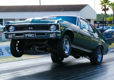
(EVEN WHEN THEIR CAR WAS PULLING THE FRONT WHEELS A FOOT OFF THE TRACK FOR 30 FEET ON A LAUNCH & RUNNING VERY LOW 10 SECOND 1/4 MILE TIMES AT OVER 136 MPH, in a 3800 LB CAR)

c3vettelaunch.jpg

leaf-spring-suspensions-400x279.jpg

Ive never worried much about what the dyno shows simply because a experienced dyno operator can play with several factors and have results swing in either direction by easily 15%
a more reliable test in my experience is car weight/1/4 mile trap speeds but keep in mind thats the car weight with you sitting in it and its real rear wheel hp , BUT THATS ONLY VALID WITH A GREAT SUSPENSION AND TIRES, IF THE DRIVE TRAINS ALLOWING THE CAR TO RUN THROUGH THE LIGHTS AT NEAR THE PEAK RPM HP, and you kept the engine operating at near peak power the whole run!
BlackoutSteve said:
There is no formula, fixed amount or fixed percentage that can be applied to every application.

Each application is different even with the same FWHP and exact same drivetrain.

Example..
Vehicle A with an engine that produces 500hp @ 5000rpm
verses
Vehicle B with an engine that produces 500hp @ 6500rpm
..will both have different rear wheel figures because parasitic losses raise exponentially as rpm increases.

Another example regarding percentage of losses would be..
A 100hp buzz-box verses a 1000hp Chevelle..
The buzz box would lose maybe 30% to produce 70hp at the wheels, where the Chevelle may only lose 15%.

A 30hp loss for the buzz-box would be considered normal, but a 300hp loss for the Chevelle would indicate (to me at least) problems.

Any formulas that indicate rear wheel figures, even with accurate and real engine figures are GUESSING. :)


http://www.gregraven.org/hotwater/calculators/qm-from-wt-hp.php

http://www.ajdesigner.com/fl_horsepower_trap_speed/horsepower_trap_speed.php

http://www.wallaceracing.com/et-hp-mph.php

http://www.cprparts.com/HPcalculator.html

http://www.calculator.net/engine-ho...d=110&v2speedunit=mph&calctype=trap&x=78&y=14

RELATED INFO
http://garage.grumpysperformance.co...ng-to-a-dyno-test-on-your-car.3175/#post-8460

http://garage.grumpysperformance.co...-results-may-or-may-not-tell.5357/#post-16030

http://garage.grumpysperformance.co...-not-always-your-parts-combo.8540/#post-29972

http://garage.grumpysperformance.co...s-in-dyno-tests-in-magazines.1817/#post-26481

http://garage.grumpysperformance.com/index.php?threads/dyno-disapointment.4947/#post-23654
 
Last edited:
Whatever it makes it makes that's what I have learned Rick.
Rear diff gearing is real important .
Street car Gear.
Top end gears.
Drag Race Low diff gears.
 
Things are not going as planned at Brand Racing Engines, so I've been
postponed for another week. I'm suppose to call this Monday and find
out for sure when to bring the engine into the shop.

Went to work gaping all 24 RN12YC spark plugs so I won't loose time
while on the dyno, just have to change plugs saving time by not having
to gap them before installation.

I found that over 1/2 the plugs were not in proper form. The center electrode
was not centered directly under the ground electrode, so I had to tweak them.
I also found that none of them had the proper gap of .044 inches. Two of
them were almost touching like the one in the photo below.

FP01_SP_StrOutOfBox_6253.jpg

FP01_SP_StrOutOfBox_6255.jpg

I used a wire gauge like the photo below to adjust all my spark plugs. A .044
inch would have a slight drag and a .045 inch wire would not go.

FP01_SP_WireGauge_6261.jpg

I used pliers to adjust the ground electrode to give the proper alignment and
gap. I was very careful not to leave a burr on the electrode during adjustment.
See the next 2 photos below.

FP01_SP_Adjusting_6257.jpg

FP01_SP_AdjustingTool_6263.jpg

After I was done the plugs looked liked the following photo.

FP01_SP_AdjustmentComplete.jpg
 
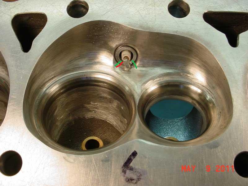
Even though I know you checked clearances during the assembly process, my first thought there, on seeing the bent ground electrodes on the spark plugs, is that you might need to INDEX the plug grounds , as the ground electrodes are being contacted and bent by the rotating assembly at higher rpms, or the plugs your using extend a bit deeper that the plugs used to check clearances???

index.php


less than ideal plug ground above, GROUND ELECTRODE CLOSER TO PISTON

MUCH better INDEXING BELOW WITH THE GROUND ELECTRODE NEAR COMBUSTION CHAMBER ROOF

DSC00757n.jpg

http://garage.grumpysperformance.co...exing-plug-ground-electrodes.4836/#post-13221

http://garage.grumpysperformance.com/index.php?threads/spark-plug-info.202/#post-35388

 
Last edited:
I'm going to have Gerald Brand Racing run some dyno tests in the next two
weeks. I hope to know later today exactly what day all this will happen.

Not sure how to plan for a dyno test, any ideas on what I should do before
the test. I have 3 sets of new spark plugs coming, should be here tomorrow.
I also have a list of questions to ask about what he needs on the engine. For
instance he has a starter to use, so I don't have one installed on arrival.

I'm also wondering how he will drive the water pump with a belt, since there
is no alternator to use for adjustments. Maybe he'll just hooks up to water
pressure and that pushes the water thru the engine and cools the motor during
tests. Something I need to know to prepare.
I watch a lot of dynos online and see both, a short belt running the water pump or electric pumps. Personally I would rather have my pump do it, it stays with the rpm the engine is running
 
my first thought there, on seeing the bent ground electrodes on the spark plugs, is that you might need to INDEX the plug grounds , as the ground electrodes are being contacted and bent by the rotating assembly at higher rpms, or the plugs your using extend a bit deeper that the plugs used to check clearances???

All 24 plugs are new and never been in the engine. I'm not having any problems
with the spark plugs coming out of the engine.

.
 
I don't know the difference from header plugs, but mine were not hard to index. I had to swap them around but they were pretty close to perfect for me already pointing at the exhaust valve. I have them numbered to go in the correct cylinder.
 
Back
Top