TH400 Amateur Build

I was just looking at your engine build thread the other day. Your PDF file is about 10 pages behind, need to update that pretty soon.

Have I done one for this thread on your trans?
Rick, wow, I guess with the car stuff on that thread I moved ahead more than I thought lol. I think as long as the engine build to start is on a pdf thats going to work fine. Other stuff like wiring, brakes etc I've got documented with plenty of pics.
Sometime when the transmission is fully assembled that will be a nice pdf document to post for anyone to have as a reference.
Thanks!
 
its always nice to see some members who obviously have skills, :like:
that I don't currently have mastered yet,:facepalm: posting info!:like:

after all the sites whole reason for existing is to help members build better cars with fewer screw-ups
I've built almost 200 engines in the last 56 years,( I lost count years ago)
I've swapped gears in several ford 9"and dana 60 differentials
and replaced gears in a muncie 4 speed, but never rebuilt an automatic trans yet!
 
Sonnax Case Saver ....

Besides my knee I've got some family issues with aging parent, so this will really be a stop and start series. Actually, it's a great benefit to put my mind onto this project as a break from the other stuff.

Anyway, onward I go....

I went back and rechecked endplay several times. I ended up with a consistent .010 measurement using the .041 bearing and two .010 shims, for a total of .161 thickness. As mentioned, spec is .007-.019 and most builders look to set it up on the tighter side. So I'm going with this endplay.
1000003103.heic.jpg

I also decided to replace the center support hollow bolt that (besides anchoring the support) pulls the center support tight against the case in order to ensure a good seal to all the fluid feeds. I'm sure the old one would be ok, just one of those things that's not much cost and a good idea to start with a brand new bolt.

TH400 center support bolts are harder to get and quite pricey, but an equally good (hardened) 4L80e center support bolt has the same thread and 12 pt head. The only difference is that it's longer. A couple minutes with my cut-off wheel and dressing the end will result in a brand new TH400 bolt.
1000003100.heic.jpg

Note! the Sonnax Case Saver partial install is shown below to just highlight some main points. The reverse band has to be installed first.

Here's the Sonnax case saver that installs over the front band anchor pin. This version is for non-trans braked applications like mine. Note that there are two types of this version, depending on what year the transmission is.

1000003104.heic.jpg

Here's a video that shows the case saver installation in a 4L80e, it's about the same for the TH400.

This is the correct installation of the case saver as related to the fretting ring. The ring is a bit droopy here, but it goes under the case saver. When everything is assembled it will be held up snug against the bottom of the case saver. The purpose of the case saver is to provide support to the fretting ring (if the transmission has one) and to the center support snap ring. That's a wide gap in that part of the case, with no snap ring support.
1000003106.heic.jpg

This is what happens if you place the fretting ring on the little ledge of the case saver - you can see it gets pulled up out of position.
1000003105.heic.jpg

I then removed the case saver and fretting ring so there was room to install the reverse band. There was a bit of horsing around getting it in there, but it fit nicely. I've not yet looked at servo travel dimension, just wanted to move forward with some more assembly. I did soak the reverse band for a couple of days to get a bit of fluid soaked into the band facing.

Here's the anchor side of reverse band - there are two depressions in the band anchor that rest against two pins in the case.
1000003109.heic.jpg

Here's the servo pin side of the band. I used the servo to ensure that the band was aligned correctly and that I could see movement when I pushed in on the servo.
1000003111.heic.jpg

There's specific servo travel measurements that will be taken to verify that the servo pin length is ok.
1000003110.heic.jpg

After the reverse band is installed, the case saver and fretting ring can be put into place.
1000003112.heic.jpg

Here's the case saver with the center support in place - you have to shift it slightly as the center support is installed, otherwise the support can hang up on it a bit. As you can see the case saver width fits right between the lugs of the center support.
In this picture the fretting ring isn't seen anymore as it's now below the center support.
1000003107.heic.jpg
 
Center Support ......

Nicks Transmission
reference video:

I was over the picture limit in the post above, but I did set the geartrain into place to ensure the relationship of the reverse band and reaction carrier was ok. The geartrain was able to turn fine, but this was with no preload on the band from the servo pin. This was just a check of general fitup, the geartrain was once again pulled out to await final installation with the center support attached.
1000003113.heic.jpg

I had held off on the center support in order to install the intermediate clutch piston.

Here's the components. That lip wizard is an amazingly simple yet effective tool for seal installations. In the picture, there are three standard duty return springs. Upon recommendation I replaced them with six heavy duty (stiffer) new springs. The idea is that the piston applies slightly harder as it takes more fluid pressure to overcome the additional three springs, then the piston releases a bit faster too.
1000003114.heic.jpg

I bought a new spiral snap ring lock for the intermediate clutch, as well as what I thought was a spiral lock for the spring retainer vs the oem snap ring. But there's a discrepancy in the diameter - the new spiral lock is smaller diameter, so I need to figure out why. You can also see the wider spiral lock ring vs the oem standard snap ring.
1000003115.heic.jpg

Here's the piston installed into the center support bore with new seals and return springs. That Lip Wizard makes all the difference safely installing new seals.
1000003117.heic.jpg

I rotated the springs a little so that they were leaning in slightly. Probably no difference, but just to lean them into the center of the spring retainer.
1000003118.heic.jpg

I went ahead and used the original snap ring for now until I resolve the question of the spiral lock ring - it was listed as spiral lock for intermediate sprag, so I may have misunderstood.
1000003119.heic.jpg

At this point, unless I tinker with that snap ring again, the lower gearset should be ready for final installation.

Edit - I had misunderstood the spiral lock application. As it had been clearly described with the product, that spiral lock is for the intermediate sprag. No mention of intermediate spring retainer so obviously I goofed that up. So re-using the snap ring for the retainer was fine.
Incidentally, that 4L80e direct drum assembly that I had bought does include the 34 element intermediate sprag and oem spiral lock. So now I've got an extra spiral lock :)
 
Last edited:
the more I've read and look at the photos you've posted the more impressive and a bit more daunting the thread becomes,
simply because its a rather new and uncharted (at least for me) area I'm trying to learn.
Yeah I felt the same way when I was tearing down my first engine with the help of a mentor when I was about 16!
I've always liked learning new stuff! :like: :fingerscrossed:

I've certainly respected yours and Ricks advice on my engine, especially when I see someone well experienced that still looks forward to learning about new stuff.
Knowledge is key in my book, and since I don't know a lot about this, its a great opportunity to learn. There's also a lot of ties to the engine, including design torque/hp that will be noted in this thread too.
 
Rear Geartrain Installation ....
Teflon Sealing Rings .....


I finished installing the rear geartrain today.

First thing was to air pressure check the intermediate clutch piston.
The pen is pointing to the fluid port on the center support where the air check is done. Very little air is needed - under 10 psi, just enought to gently move the piston up. All went well with this check, piston moved freely, no air leaks.
1000003174.heic.jpg

I had decided to replace the stock steel sealing rings on the center support stator with Teflon seals, generally regarded as a better sealing option. I bought a complete Teflon sealing ring kit for the transmission rather than piecemeal these.
1000003175.heic.jpg

There's a couple of different types of teflon seals - one-piece and scarf-cut.
I went with the scarf cut seals as they were easy to install and didn't to be re-sized after installation like the one-piece seals would require.
1000003176.jpg

Using lots of blue lube, I eased them onto the stator, making sure that the scarf locations didn't line up with each other (just like we do with piston rings), and that the scarf cuts overlapped properly on each seal. I also added blue lube to hold the seals in place. Pretty straightforward.

You'll notice that the second seal has been left out - this is for the dual feed mod that you see described all over the internet. There's plenty of detail out there, but this modification essentially creates a major cross leak between the reverse and direct circuits as I understand it. This allows the full area of the direct drum piston to be used for 2-3 clutch application instead of just half the piston area. The piston area is separated by seals for reverse and direct - this modification removes the separating seal. I'll cover this a bit later when I get to the direct drum.
1000003178.heic.jpg

The center support was then installed into the gear trains, using a gentle ccw rotation to ease it into the low roller clutch assembly. Rotation was checked yet again, with ccw rotation ok, then locking when rotated cw. That little lifting tool has been great!
1000003179.heic.jpg

Next was to cut the new 4L80e center support feed bolt (bottom) to proper length. I believe that the original longer version works in cases 1990 and up. I decided to simply hacksaw the bolt and dress the end instead of using a cutoff wheel. I wasn't sure if the heat from the cutoff would affect the bolt hardness.
1000003180.heic.jpg

The gear train assembly was lowered (I hope for the final time) into the case. The center support beveled snap ring was installed - the usual 9 o'clock position of the open end of the snap ring was slightly shifted to ensure it securely held the case saver in place, per Sonnax directions.
1000003183.heic.jpg

As this was done, the center carrier (hollow) bolt was loosely installed, per ATSG instructions. After the snap ring was installed, I followed ATSG which said to use a drift or similar to apply ccw pressure to the center support through the left feed hole, while tightening the carrier bolt to 22 ft. lbs. I assume this was to thrust the center support against the lugs. Anyway, this was done, another straightforward job.
1000003182.heic.jpg

I continued to check for smooth rotation as assembly continued. Feels a lot different from the original setup due to all the new bushings installed, a good easy yet "snug" rotation feel. Now I can really see how loose the original setup was, makes me glad I went with new bushings..
1000003186.heic.jpg
 
Reverse Feed Block-off .....
(Part of Dual Feed Mod)

The other part of the dual feed mod is to use a 3/8 in cup plug to block the reverse oil passage to the center support. It's the hole to the right of the carrier bolt.
1000003185.heic.jpg

I bought a couple of parking pawl cup plugs from Amazon - they are the right size for this application. I just needed one plug, but I got an extra just in case. I've seen where they are supposed to be usually supplied in th400 rebuild kits, but there were none in my kit, and its a Level 2 kit that's supposed to include "everything".
1000003184.heic.jpg

I used red threadlocker on the plug and a smooth end punch to tap it into position. It all went very well, the plug tapped into place with what felt like the right resistance and then bottomed against the center support. That's a primary reason why the center support needs to be in place when the plug is installed. I also liked that the wall thickness of this plug wasn't so thick that it distorted the valve body opening.
1000003187.heic.jpg
1000003188.jpg

Next up I'm going to get the intermediate clutches in place.

The original parts.
1000003189.heic.jpg

And what I need to get this done. I have a couple of new steels and three new clutches.
I'll need to verify what clutch clearance is needed to see what thicknesses of steels are applicable.
1000003190.heic.jpg
 
I wanted to specifically identify and thank Nick's Transmissions which has many different transmission rebuild videos on YouTube.

Nick's Transmissions

His th400 rebuild series has been my main guide and he's been kind enough to answer my questions.

He's like the Grumpy and Rick of my transmission world :like:
 
I went with the scarf cut seals as they were easy to install and didn't to be re-sized after installation like the one-piece seals would require.
1000003176.jpg
You are right the one piece seals that I used were a bear to get installed. The scarf cut are super easy.
 
Intermediate Clutch ....

Moving further into the intermediate clutch now....

This shows the new clutches and steels, along with the old steels, wave washer and pressure plate. In general, sifting my way through information, I agree with a general preference for waffle type clutches and thicker steels. The waffle type are thicker than the smooth type clutches, and the grid helps retain fluid in the clutch surface. The thicker steels are more heat resistant.
1000003190.heic.jpg

However, in order to get to a specific clutch pack clearance specification (generally .010 per clutch), a combination of thicker and thinner clutches/steels needs to be used. For this build, I'm not getting into machining parts or pistons, that's above my pay grade.

First thing, the Sonnax Case Saver requires a small notch cut into the intermediate clutch pressure plate, not a big deal, and no affect on the plate operation. The notch is essentially equal to one lug on the plate.
You can see the bluing and white mark indicating the area that needs to be modified. The pressure plate fits into the case lugs, so its fixed into position, no guesswork on where the notch needs to go.
1000003245.jpg

Here's the pressure plate, you can see the solid no-lug section that ends up approx. at the 9 o'clock position when in the case. I've already done the notch in it, this is just to see the plate shape.
1000003262.jpg

Placing an intermediate steel onto the pressure plate and matching the lugs clearly shows where the notch goes (pencil pointer). The Case Saver itself is designed to fit into the lug pattern of the case, as was shown when the center support was installed.
1000003264.jpg
1000003246.jpg

I did what Sonnax recommended, which was to use a hacksaw to cut notches, then file as needed. Straightforward and it only needs to clear the Case Saver, so supreme accuracy isn't needed.
1000003247.heic.jpg

Here's the pressure plate in place, now clearing the Case Saver.
1000003251.heic.jpg
 
Intermediate Clutch ....

Now we get into figuring out what combination of clutches and steels will provide spec clearance.

The original setup used smooth clutches.
1000003189.heic.jpg

The kit that I wanted and ordered has the waffle clutches, which I will use whenever possible.
1000003190.heic.jpg

I also went with a spiral snap ring vs stock snap ring on the intermediate clutch pack. The stock snap ring is almost always replaced by a more robust snap ring, and they can be bought in different thicknesses. You can see the difference on the spiral vs stock snap rings.
1000003239.jpg
1000003241.heic.jpg

I installed the wave plate and waffle clutches and two new steels. I used one of the original steels too, a bit thinner.
1000003231.jpg

However, when I placed the pressure plate on top of the clutch pack, there wasn't enough space in the lug notches for the snap ring.
1000003252.jpg

So, time to start figuring and adjusting. The intermediate has the largest diameter clutches/steels - I don't have any extras of different thicknesses, so I'll have to order some parts. I'll verify the preferred sweet spot, but the overall clutch clearance needs to be in the .050 range I believe.

Here's some numbers, taking into account there's some wear on the original parts. This is just to get an idea of starting point and where we are heading. I didn't take a clearance measurement of the original clutch pack and I hope Rick checks my math :)

Snap Ring Thicknesses (not installed yet)
Stock original = .093
New spiral type = .086

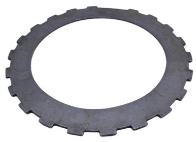
Original Clutch Pack Thicknesses
Original smooth clutch = (3) average of .078
Original steel = (2) .100
Original steel = (1) .070
Original wave = (1) .067, just material thickess, not including the wave height
Original Pressure Plate = (1) .323
Total Thickness = .894

New Clutch Pack Thicknesses (first pass)
New waffle clutch = (3) average of .092
New steel = (2) .098
Original steel = (1) .070
Original wave = (1) .067, just material thickess, not including the wave height
Original Pressure Plate = (1) .323
Total Thickness = .932

I've got an immediate thickness increase of .038, and I can't fit the snap ring into the case lug grooves. Meaning that there is zero clearance in the clutch pack, and I've got to reduce the thickness by at least that .038 amount to see what ballpark the overall clearance may be in. So now I need to do some research on clutches/steels and decide what to get. I don't want to use Alto smooth clutches as they are very thin - if I do need smooth clutches, I'll use Raybestos or Borg Warner.

Edit - it seems that most th400 have .080 smooth frictions in the intermediate. I'm not sure why this kit has .092 frictions, but I went ahead and ordered three .080 waffle type Raybestos frictions. I want to keep the steels as thick as possible, and the wave plate will be re-installed for shift cushioning. And I'll use the thinner spiral snap ring. So I should be able to look at combinations of frictions and steels to get to desired pack clearance.

In the meantime I can mess with the 4L80e direct drum clutch setup, install the piston, etc.
 
Last edited:
The stock snap ring is almost always replaced by a more robust snap ring, and they can be bought in different thicknesses.
How much can you make up with a snap ring change?

Looks like you might have to use 2 steel plates of .070" thickness and 1 of .098" thickness to make up .028" of the .038". I wonder if you could take off another .010" by hand on the Pressure Plate. This would allow you to fine tune the clearance, sneaking up on the clearance you want while taking measurements.

What about the wave plate effective thickness, are they the same? I see where some put a flat steel plate in place of the wave plate, would that make the shift too harsh?

The steels (.063") below would give you another .007" or .005" depending on which steel you replaced.


and I hope Rick checks my math :)
Yeap, it all looks good !
 
Rick, thanks for the math check! I need that review!

There's a variety of snap ring thicknesses available, I'd rather use the spiral, but if I had to, I could find another thickness in a regular snap ring. Almost all aftermarket are wider than the stock ring, which is good.

I had edited my earlier post after doing some research:
Edit - it seems that most th400 have .080 smooth frictions in the intermediate. I'm not sure why this kit has .092 frictions, but I went ahead and ordered three .080 waffle type Raybestos frictions. I want to keep the steels and the clutches as thick as possible, and the wave plate will be re-installed for shift cushioning. And I'll use the thinner spiral snap ring. So I should be able to look at combinations of frictions and steels to get to desired pack clearance.
--------------------------------------
Keeping the steels thick is mainly for heat resistance, and I'm reluctant to go any thinner than .080 on the frictions and .070 on the steels in the intermediate, where there's only three of each. Using the combo of three .080 frictions, two .098 steels, one .070 steel "should" be an almost duplicate of the original setup, and ill see where the clearance lands with the .086 spiral ring and stick wave. From what I read, a bit looser is better on the intermediate stack.

Almost everyone recommends leaving wave plates in place for heavier duty street applications like mine to help control shift harshness. I think on transbrake or full race applications that's a different story.
 
I did see a thinner pressure plate if that's something that would work for you I could probably find it again.
 
Direct Drum.....

While waiting on intermediate clutch frictions, I moved on to the direct drum.

Another reference video....

This was the 4L80e direct drum assembly from Ebay, it all looks very good. It was more cost effective to get the whole assembly vs buying separate piston, spring retainer, 34 element sprag and spiral lock ring.
1000003303.heic.jpg

The 4L80e sprag uses a spiral snap ring instead of a standard snap ring as the sprag retainer. Even if you're using a th400 drum, the spiral lock is recommended.
1000003313.heic.jpg

Molded piston, the seals were in excellent condition. I'll explain the 1 and 2 marks next picture.
1000003309.jpg

As part of the dual feed mod, the seal that the orange pick is pointing to is left out. This matches up with the second sealing ring that was left out on the center support stator. This allows the entire piston surface to act as one surface instead of the two small separate sections as shown in the picture above.
The blue awl is pointing to a location where a lot of builders add a small bleed hole through the drum. Recommended for transbrake applications and high rpm >6500 rpm engine speeds. My application requires neither, so I'm not drilling this bleed hole. The drum does have the standard bleed/checkball in it as you can see. There is no bleed hole in the piston.
1000003307.jpg

The molded piston has been installed along with the return springs/retainer (one piece assembly) and that's a new spiral lock for the retainer on this side of the drum. I was glad I had my compressor tool and press, there's a lot of spring tension from all those springs. This is all stock 4L80e stuff. The Lip Wizard tool makes piston installation very easy, just go slow and apply steady light downward pressure on the piston while rolling the tool around the lip.
1000003315.heic.jpg
1000003312.jpg

These oem spiral locks have a little lock tab on them to ensire the top spiral hooks onto the turn below it. A bit fiddly to do, but they must mesh in order for the spiral lock to seat properly in the groove. Big improvement over the stock snap ring.
1000003317.jpg

On the other side of the drum, the 34 element sprag was installed. This picture was taken before the flat retainer plate was in place, meaning I forgot it!162024162923.jpg

Everything is now properly installed and lubed. Very good rotation feel of the sprag assembly, and the drum race looked great. I wrote the correct rotation on the drum itself and verified the the sprag turned CW and locked CCW. Very easy to install - it goes inside that outer splined race as a good snug fit (see above). The outer race itself has the dual rings cast into it for the "up" side). Just like the low roller clutch in the center support, you have to work a bit to get it into place.
162024165024.jpg

Here's a good comparison of the 4L80e sprag thickness vs the TH400 sprag on the right.
The 4L80e sprag not only has the 34 element roller, but it's also slightly thicker than the TH400 sprag. The depth ensures that it fits fully into the intermediate clutch pack. It also has 4 large fluid holes in the perimeter, and the splines look a bit more robust as well. I think this is a good upgrade for the TH400.
1000003365.jpg
 
Last edited:
Direct clutch pack...

This is a five-clutch setup. I don't want or need to add another clutch because the steels will get way too thin to get the proper clearance. Since they act as heat sinks, the thicker I can keep them the better. The kit has ten .080 fibers and about the same or so steels of different thickness, plus I have the original steels, many in good shape that can be used if needed.
The clutches/steels are the same for the direct and the forward drums, so the steels can be mixed and matched as needed to get to proper clutch stack clearance in each drum.
1000003302.heic.jpg

Original clutch pack was five fibers/steels, no wave plate at the bottom. I'll duplicate the setup without the wave plate.
EDIT - that's not correct. The original TH400 direct setup didn't have a wave plate, but after a quick check of 5 fibers/steels in this 4L80e drum, there's a whole lot of clearance. I don't want a 6 clutch setup, as the steels get thin. After some research, it appears that this 4L80e direct drum was originally provided with a wave plate. I was comparing apples and oranges.
I ordered Transgo TH425 3127A wave plate at .068, there's also a TH400 wave plate at .060, but I had a hard time finding one. Wave plates are interchangeable between these transmissions.
1000003314.jpg

I'll get into setting up the direct clutches after I get the additional wave plate. I may also work on the forward drum at the same time in order to use the steels efficiently in both drums. I want to use up all the new steels before re-using any of the original steels.
 
Last edited:
Forward clutch.....

In general, this drum and clutch assembly seems to show the most wear of all the components so far. I guess it makes sense because - if I've got it right - the forward clutch is in operation most of the time.

These are the upgrades that I bought for the forward clutch:

Aluminum piston on the left to replace the stock steel on the right. You can see the difference in the "shelf" that the fibers or steels sit on, also the difference in the spring retention. I set a clutch on them to hopefully show the difference in support. Neither of these has a checkball, so if you're replacing the stock version, match the new one with the checkball setup, as some pistons did have a checkball.
1000003366.jpg

Sonnax heavy duty spring retainer. It's simply a heavier gauge steel than the stock one on the right.
Also shown is the new spiral lock retainer vs the stock snap ring on the right.
1000003370.jpg

Sonnax steel forward hub on the left vs the stock cast iron hub on the right. Maybe not a requirement, but a bit of insurance on this part.
1000003368.jpg

I'm re-using the direct clutch hub (it's attached to the forward drum), but I needed to clean up the surface a bit. Not terrible, but needing some attention.
1000003371.heic.jpg
1000003372.jpg

I used my trusty leveling block that I've modified with flat aluminum plate to ensure all is level.
1000003373.heic.jpg

I added some light oil and then ran the hub in circular pattern over the 600 grit paper.
1000003374.heic.jpg

Just a general smoothing and a surface cleaning.
1000003395.jpg

The forward has a five-clutch setup plus wave plate that I will duplicate. The steels are in the .075-.078 range. The steels do show some bluing spots from heat, but the clutches were all in reasonable condition. I've not found one burned clutch in this transmission.
1000003375.heic.jpg

I'm not liking the wave plate - looks like it's had some heat on it from the bluing. It also makes me think about how that repeat heat cycle may have affected the spring (cushioning action) of the wave.
1000003367.jpg

I did find TH400 wave plates, so here's what I've got ordered to hopefully finish up both the forward and direct clutch packs (note that direct and forward steels/fibers are all the same diameters).

- (2) TH400 wave plates (.060)
- (1) TH425 wave plate (.068)
- (3) intermediate frictions (.080)

I'm giving myself a little wiggle room in the wave plates - they can be used in either the forward or the direct drum. I'll wind up with one extra but that's ok. So for now, the intermediate, direct and forward clutch assembly is on hold until I get these parts.
 
Forward Drum Piston ....

I decided to at least get the forward piston into the drum, one less thing to do later.

Here's the drum, the pick is pointing to the checkball. I ensured that it moves freely. The original center seal is still in place - for a novice like me, I leave all the seals in place until I'm actually ready to replace them. My bucket holder is coming in handy, as the input shaft is attached to the forward drum.
1000003376.heic.jpg

Generally, the seal lip points towards the motion of the piston to capture the fluid pressurizing the movement.
This center seal in the drum points up. I also noticed that the three seals for this drum/piston were "ok" but were not quite as pliable as in the other assemblies.
1000003388.heic.jpg

New seal with the same orientation.
1000003392.heic.jpg

Original piston seal orientations - shown here with the piston upside down on the bench. They will point down into the drum on installation.
1000003390.heic.jpg
1000003391.heic.jpg

New seals on the "new" (ebay) aluminum piston installed to match the orientation. That's discoloration on the piston.
1000003393.heic.jpg

Installed the piston, plenty of blue lube and using the Lip Wizard tool. This one was the fiddliest to get into place, but it's in there fine. One learning curve here - I'll leave the springs/retainer off until after I check clutch pack clearance. Makes using a feeler gauge much easier.
1000003394.heic.jpg

I'll still do air checks on all drums.
 
Back
Top