You are using an out of date browser. It may not display this or other websites correctly.
You should upgrade or use an alternative browser.
You should upgrade or use an alternative browser.
TH400 Amateur Build
- Thread starter TXChevy
- Start date
while technology is constantly advancing, and I love working on the muscle-car era cars,
most of us tend to work with or modify the engine or drivetrain that came with the original car!
that's VERY understandable as it insures you run into far fewer fit & function issues.
only the marginally insane and well equipped hot rodders like myself tend to assemble combos of parts,
the factory engineers never thought of, (mostly because the OLDER cars were built before those components existed)
SO GUYS WITH MARGINAL COMMON SENSE (yeah i'm guilty at times)
TRY RETRO-FITTING NEWER PARTS IN OLDER CARS)
its been my experience that extensive research, before you open your wallet, tends to save you a ton of miss spent cash,
yes a TH400 can be built to handle an amazing amount of power, but it lacks an over drive top gear,
its main great features are strength and reasonably low cost and well known technology, easy to locate parts,
some of the newer transmissions don't have rebuild parts available yet.
you always have options, so do research before jumping into any project,
there's always better and newer options, the TH400 is at least 50 plus year old tech,
even the marginally more recent 4l80E has overdrive and similar strength, there's zero wrong with either trans
either are a darn strong transmission, but if you don't have one already there are several newer and marginally stronger drive train components (transmissions) that MIGHT BE a better option in some applications that add easy software programable programing and over drive gearing
I know I bought a 4l80E for my C4 corvette BBC engine swap project, I probably should have waited and bought a 6L90e
6L90E comes to mind
as it has two over drive gears and from the factory handles about 700 hp,
 globaltransmissionparts.com
most of us tend to work with or modify the engine or drivetrain that came with the original car!
that's VERY understandable as it insures you run into far fewer fit & function issues.
only the marginally insane and well equipped hot rodders like myself tend to assemble combos of parts,
the factory engineers never thought of, (mostly because the OLDER cars were built before those components existed)
SO GUYS WITH MARGINAL COMMON SENSE (yeah i'm guilty at times)
TRY RETRO-FITTING NEWER PARTS IN OLDER CARS)
its been my experience that extensive research, before you open your wallet, tends to save you a ton of miss spent cash,
yes a TH400 can be built to handle an amazing amount of power, but it lacks an over drive top gear,
its main great features are strength and reasonably low cost and well known technology, easy to locate parts,
some of the newer transmissions don't have rebuild parts available yet.
you always have options, so do research before jumping into any project,
there's always better and newer options, the TH400 is at least 50 plus year old tech,
even the marginally more recent 4l80E has overdrive and similar strength, there's zero wrong with either trans
either are a darn strong transmission, but if you don't have one already there are several newer and marginally stronger drive train components (transmissions) that MIGHT BE a better option in some applications that add easy software programable programing and over drive gearing
I know I bought a 4l80E for my C4 corvette BBC engine swap project, I probably should have waited and bought a 6L90e
thoughts & ideas related too, modernizing/ improving the older corvettes
if you own a c1-c4 corvette, you know there's dozens of feature's upgraded components or mods or upgrades in the gauges,OPTIONS, drive train and suspension, brakes etc, that more modern corvettes have, that in many cases can be upgraded and used on the older corvettes, if you have some...
garage.grumpysperformance.com
anyone have experience converting a 4l80E to full manual?
https://www.google.com/url?sa=t&source=web&rct=j&url=http://www.atra.com/Gears/2015/2015-03/2015_3_32.pdf&ved=2ahUKEwi6qJiC7ObfAhVisYsKHX3DAWYQFjAKegQIAhAB&usg=AOvVaw1cAAGGXHLjLsKC2ZZ6xR6s
garage.grumpysperformance.com
6L90E comes to mind
as it has two over drive gears and from the factory handles about 700 hp,
General 6L80 6L90 Transmission Specifications & Info
General information and specifications plus great high performance replacement parts for GM 6L80 and 6L90 automatic transmissions from Global Transmission Parts.
Last edited:
I honestly don't remember the shift points. I had a B&M basic shift kit (slightly larger holes in separator plate) and 6 checkballs. I'll re-use the plate after I research the hoke sizing and go with 5 checkballs.Will you be modifying the shift points with changes to the governor or valve body?
What are the shift points before you started the rebuild?
.
I'll wait on the governor till I road test it, easy to modify.
please keep in mind when I post info or tips , or links, they MAY OR MAY NOT be directed at anyone in particular,
who may or may not have previously posted info or commented on the main topic of the thread,
it's just info I felt the links or info or advice needed to be included for people reading through the thread months or a year from now. as it might help them make more informed choices
for better or worse I tend to think like an engineer and think about what the thread might be used for and the potential ,
the threads contents and links have to help people even a year or more in the future
who may or may not have previously posted info or commented on the main topic of the thread,
it's just info I felt the links or info or advice needed to be included for people reading through the thread months or a year from now. as it might help them make more informed choices

for better or worse I tend to think like an engineer
 and think about what the thread might be used for and the potential ,
the threads contents and links have to help people even a year or more in the future
please keep in mind when I post info or tips , or links, they MAY OR MAY NOT be directed at anyone in particular,
who may or may not have previously posted info or commented on the main topic of the thread,
it's just info I felt the links or info or advice needed to be included for people reading through the thread months or a year from now. as it might help them make more informed choices
for better or worse I tend to think like an engineerand think about what the thread might be used for and the potential ,
the threads contents and links have to help people even a year or more in the future
Oh, I didn't take anything wrong at all, it was a valid comment. There's a lot of benefit to gaining 6 speeds in approximately the same size unit!
I just wanted to assure you that you were doing a very nice job, but at the same time point out to future readers that there's almost alway options, as you gain age/wisdom, you tend to look back on some decisions you made in the past, and say to yourself %%^&*& 
what was I thinking??
Theres almost always several routes that anyone can take to accomplish similar goals and that a good deal of research rarely hurts.
I know from personal experience that one of the huge issues I personally had was running into "DEALS" or really good prices on components that did not match or work towards improving my projects, that frequently resulted in me not having the required funds when the deal on the parts I really wanted happened, and of course diving right into spending a good deal of time and cash building or rebuilding what you currently have access to, rather than what you really intended to build.!
its really a good idea to take the effort to plan out your cars build with as many of the characteristics and ideal components listed
and take the effort to make sure the parts all work reasonably well at the engine rpm and power levels, you intend to operate at... obviously be realistic and keep your bank balance, and skill level and availability of a place to work and tool access in mind!

what was I thinking??

Theres almost always several routes that anyone can take to accomplish similar goals and that a good deal of research rarely hurts.
I know from personal experience that one of the huge issues I personally had was running into "DEALS" or really good prices on components that did not match or work towards improving my projects, that frequently resulted in me not having the required funds when the deal on the parts I really wanted happened, and of course diving right into spending a good deal of time and cash building or rebuilding what you currently have access to, rather than what you really intended to build.!
its really a good idea to take the effort to plan out your cars build with as many of the characteristics and ideal components listed
and take the effort to make sure the parts all work reasonably well at the engine rpm and power levels, you intend to operate at... obviously be realistic and keep your bank balance, and skill level and availability of a place to work and tool access in mind!
Last edited:
Intermediate Clutch .....
In our last exciting episode, I had left off on the intermediate to wait for three .080 waffle frictions with the intent to replace the kit-supplied .092 frictions. The reason was that using the .092 frictions resulted in way too tight of a clearance.
I was wrong! Another chapter of the learning curve resulted, at least this time it didn't cost a lot for the lesson.
But let's start where I started today.
New green .080 frictions next to the .092 friction.
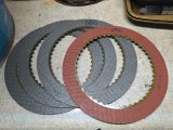
I saw an interesting comment about waffle vs smooth frictions that seemed to make sense. There's a laminar fluid flow that occurs across the clutch surface during operation. As the clutches are applied, there may some resistance to fluid being pushed out of the surface, something like when it's difficult to split two smooth discs apart when they are wet. The waffle surface gives the fluid a quick exit and also helps with heat dissipation for fluid flow throughout the friction surface. Obviously there's a lot of factory transmissions with smooth frictions - this unit had them - but it did seem that the waffle surface may have some benefits. Not an expert, just an observation on what I found.
The basis of my error was in how I took the previous clearance measurement.
It cannot be taken like this, using the direct drum as an example:
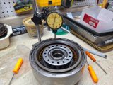
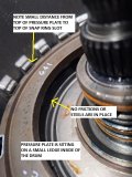
Putting the dial indicator on top of the pressure plate only gives you a tiny amount of play. That play is from the top of the pressure plate to the snap ring. The pressure plate does not sit directly on the clutch friction, as there's a small ledge inside of the drum or center support.
In this picture the center support pressure plate is sitting on the small ledge - as you can see, there are no frictions/steels below it. When the clutch stack is installed, including the snap ring, the only measurement you'll get is the little movement from the pressure plate being pushed up tight against the snap ring.
A good way to find clutch pack clearance is to use a combo of feeler gauges between the top friction and the pressure plate. The feeler gauges also push up on that slight play of the pressure plate/snap ring gap.
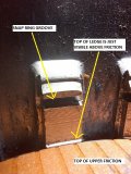
I also found some info on getting into the general ballpark - as you load the stack, the last (top) fiber should be just below that small ledge. That's just a starting point, but if the fiber is above, there won't be any clearance using a stock pressure plate.
In the picture below, this was my final clearance on the intermediate, which is fine. That's a .020 and a .025 feeler stacked together. There's a general rule of thumb of .010/friction, but I found some more-preferred stack clearances. Also in the picture is a spiral-lock snap ring (.086) that replaced the standard stock snap ring (.093). One key advantage is the width of almost any snap ring you get - the replacements are much wider and can be found in different thicknesses to help with clutch pack clearance setup.
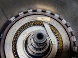
I did several stack assembly trial runs to get to the final clearance of .045.
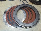
The final combination (bottom to top) was:
(1) wave plate (plate is .070 thickness, but the overall wave depth is somewhere around .110)
(2) steels at .098
(3) frictions at .092 (the new .080 frictions weren't needed)
(1) pressure plate .325
(1) spiral snap ring .086
Of course, your combo may vary.
After I verified the clearance, I did a 30 psi air check, using a small regulated compressor. You don't want to run 100 psi or you'll blow the seals out. The little compressor works great for this.
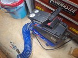
Air is applied through the hollow center support bolt.
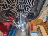
Beautiful apply of the intermediate piston - very solid THUNK with good hang time. Very pleased.
I then went back and re-checked the stack clearance now that the piston had cycled a few times.
So, then it was time to give the frictions a soak.
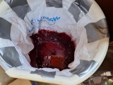
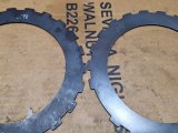
In the meantime, I cleaned up the surface of the new Kolene steels, usually recommended to do this.
Just a light scotchbrite application, difference is on the right.
My plan is to get intermediate/direct/forward clutch packs finished and clearance checked, then soak the frictions while I do additional measurements of the input, etc.
I'll then be ready to final-assemble the clutches/drums and the rest of the transmission.
In our last exciting episode, I had left off on the intermediate to wait for three .080 waffle frictions with the intent to replace the kit-supplied .092 frictions. The reason was that using the .092 frictions resulted in way too tight of a clearance.
I was wrong! Another chapter of the learning curve resulted, at least this time it didn't cost a lot for the lesson.
But let's start where I started today.
New green .080 frictions next to the .092 friction.

I saw an interesting comment about waffle vs smooth frictions that seemed to make sense. There's a laminar fluid flow that occurs across the clutch surface during operation. As the clutches are applied, there may some resistance to fluid being pushed out of the surface, something like when it's difficult to split two smooth discs apart when they are wet. The waffle surface gives the fluid a quick exit and also helps with heat dissipation for fluid flow throughout the friction surface. Obviously there's a lot of factory transmissions with smooth frictions - this unit had them - but it did seem that the waffle surface may have some benefits. Not an expert, just an observation on what I found.
The basis of my error was in how I took the previous clearance measurement.
It cannot be taken like this, using the direct drum as an example:

Putting the dial indicator on top of the pressure plate only gives you a tiny amount of play. That play is from the top of the pressure plate to the snap ring. The pressure plate does not sit directly on the clutch friction, as there's a small ledge inside of the drum or center support.
In this picture the center support pressure plate is sitting on the small ledge - as you can see, there are no frictions/steels below it. When the clutch stack is installed, including the snap ring, the only measurement you'll get is the little movement from the pressure plate being pushed up tight against the snap ring.

A good way to find clutch pack clearance is to use a combo of feeler gauges between the top friction and the pressure plate. The feeler gauges also push up on that slight play of the pressure plate/snap ring gap.
I also found some info on getting into the general ballpark - as you load the stack, the last (top) fiber should be just below that small ledge. That's just a starting point, but if the fiber is above, there won't be any clearance using a stock pressure plate.

In the picture below, this was my final clearance on the intermediate, which is fine. That's a .020 and a .025 feeler stacked together. There's a general rule of thumb of .010/friction, but I found some more-preferred stack clearances. Also in the picture is a spiral-lock snap ring (.086) that replaced the standard stock snap ring (.093). One key advantage is the width of almost any snap ring you get - the replacements are much wider and can be found in different thicknesses to help with clutch pack clearance setup.

I did several stack assembly trial runs to get to the final clearance of .045.
The final combination (bottom to top) was:
(1) wave plate (plate is .070 thickness, but the overall wave depth is somewhere around .110)
(2) steels at .098
(3) frictions at .092 (the new .080 frictions weren't needed)
(1) pressure plate .325
(1) spiral snap ring .086
Of course, your combo may vary.

After I verified the clearance, I did a 30 psi air check, using a small regulated compressor. You don't want to run 100 psi or you'll blow the seals out. The little compressor works great for this.

Air is applied through the hollow center support bolt.

Beautiful apply of the intermediate piston - very solid THUNK with good hang time. Very pleased.
I then went back and re-checked the stack clearance now that the piston had cycled a few times.
So, then it was time to give the frictions a soak.

In the meantime, I cleaned up the surface of the new Kolene steels, usually recommended to do this.
Just a light scotchbrite application, difference is on the right.

My plan is to get intermediate/direct/forward clutch packs finished and clearance checked, then soak the frictions while I do additional measurements of the input, etc.
I'll then be ready to final-assemble the clutches/drums and the rest of the transmission.
The same as a tire with very little tread on a wet surface ....... hydroplaning occurs.As the clutches are applied, there may some resistance to fluid being pushed out of the surface, something like when it's difficult to split two smooth discs apart when they are wet. The waffle surface gives the fluid a quick exit
I'm confused, if the pressure plate sits on the ledge, then it can't push on the friction plate if it's below the ledge??? The pressure plate can only move between the snap ring the ledge.I also found some info on getting into the general ballpark - as you load the stack, the last (top) fiber should be just below that small ledge. That's just a starting point, but if the fiber is above, there won't be any clearance using a stock pressure plate.
Seems when taking a measurement with the feeler gauges you would need to measure in TWO places, one being 180° from the other. Otherwise you are just pushing one side up and the other side down [180° from the other].
1) wave plate (plate is .070 thickness, but the overall wave depth is somewhere around .110)
(2) 2 - steels at .098
(3) 3 - frictions at .092 (the new .080 frictions weren't needed)
(1) pressure plate .325
(1) spiral snap ring .086
0.110 + (2x.098) + .(3x.098) + .323 +.086 = .991
Earlier you got 0.932 for the thickness, shown below. I get 0.991 for the above calcs. Also the pressure plate changed from 0.323" to 0.625", did you change your mind on the pressure plate.
New waffle clutch = (3) average of .092
New steel = (2) .098
Original wave = wave plate (plate is .070 thickness, but the overall wave depth is somewhere around .110)
Original Pressure Plate = (1) .323
Spiral snap ring .086
Total Thickness = .932
Are you going to measure pressures after startup to verify those are correct?Just a few minutes to install the NPT plug on the drivers side pressure port, because there's always a good chance I'll forget.
.
Rick, this is why I think the help here is terrific - both you and Grumpy ask constructive/challenging questions that make me think. I've seen where not only where I miss stuff/errors, but there's some assumptions I've made without really considering alternatives. So thanks as always.The same as a tire with very little tread on a wet surface ....... hydroplaning occurs.
I'm confused, if the pressure plate sits on the ledge, then it can't push on the friction plate if it's below the ledge??? The pressure plate can only move between the snap ring the ledge.
Seems when taking a measurement with the feeler gauges you would need to measure in TWO places, one being 180° from the other. Otherwise you are just pushing one side up and the other side down [180° from the other].
1) wave plate (plate is .070 thickness, but the overall wave depth is somewhere around .110)
(2) 2 - steels at .098
(3) 3 - frictions at .092 (the new .080 frictions weren't needed)
(1) pressure plate .325
(1) spiral snap ring .086
0.110 + (2x.098) + .(3x.098) + .323 +.086 = .991
Earlier you got 0.932 for the thickness, shown below. I get 0.991 for the above calcs. Also the pressure plate changed from 0.323" to 0.625", did you change your mind on the pressure plate.
New waffle clutch = (3) average of .092
New steel = (2) .098
Original wave = wave plate (plate is .070 thickness, but the overall wave depth is somewhere around .110)
Original Pressure Plate = (1) .323
Spiral snap ring .086
Total Thickness = .932
Are you going to measure pressures after startup to verify those are correct?
.
Pressure Plate
The pressure plate (other than having a little wiggle depending on the snap ring thickness) doesn't do the pushing - it's the piston under the clutch pack that used fluid pressure to push the clutch pack upwards into the pressure plate. The piston is moving upwards inside the drum, compressing the clutch pack against the pressure plate which is retained by the snap ring.
Clearance Measurement
When I used the feeler gauges to measure clearance, they also pushed the pressure plate up against the snap ring so I could see what the total clearance was. There's a spec range for clearance, so this measurement should be applicable, it doesn't have to be to the thousandth (thankfully). I also checked with your input about 2 measurements at 180d but it didn't really make a difference. I see your point, but maybe the diameter isn't large enough not to really make a difference. But well worth a double check.
Clutch Pack Thickness
I had to go back and look at again, it's been more than a day lol.
I realized that measuring the old clutch pack thickness didn't really offer any real comparison because the key measurement is the new stuff that's being installed. I never did go back and try to make further reference to the original setup because I had never measured the clearance of the original setup. What I do remember is that every clutch pack felt pretty loose, but that's subjective of course.
There's some factors that came to light as I thought about all this .....
Original Clutch Pack Thicknesses
Original smooth clutch = (3) average of .078
Original steel = (2) .100
Original steel = (1) .070 NOTE I thought this was a steel but it's actually a wave plate, so there's a wave height that's applicable
Original wave = (1) .067, just material thickness, not including the wave height
Original Pressure Plate = (1) .325, using .093 standard snap ring (minor correction on thickness, no real impact)
Total Thickness = .894 this isn't a correct thickness due to the additional wave plate height that I missed.
New Clutch Pack Thicknesses
(1) wave plate (plate is .070 thickness, but the overall wave depth is somewhere around .110)
(2) steels at .098
(3) frictions at .092 (the new .080 frictions I just bought weren't needed)
(1) Original pressure plate .325 using .086 spiral lock snap ring
I moved away from looking at or comparing total pack thickness and simply worked the components to get the proper clearance. If I did just generally add in the second wave plate at about .110 to the original pack, it's in the range of .894 + .110 = 1.004, not too far from .991. So I'm thinking that it's at least around the general range. I'm not sure about a .625 pressure plate?
I have no idea why this original intermediate clutch pack had two wave plates, and there's no question that it did have two. But I'm not using the original .067 wave plate - this allowed the use of the thicker .092 frictions instead of the .080 frictions that I thought were needed. I liked that, thinking about heat dissipation. I want wave plates in all the clutch packs, but I didn't need two of them in a pack.
Sequence from the bottom = wave, friction, steel, friction, steel, friction, pressure plate.
This is the second head scratcher I found on this original unopened transmission. The first was the three horseshoe clips on the pump pressure regulator instead of the standard single clip. I believe that the additional clips would have resulted in increased line pressure.
Speaking of line pressure (what a great segue), I had totally ignored the value of the pressure port, just assumed I put the plug back in and away I go. But your question showed me I was missing the boat!
I'm going to install a JIC fitting in there instead and use a 1/8 NPT fine thread to #4 JIC flare fitting. I'm already planning to make or buy some PTFE lined braided hoses for the transmission cooler line ends (at cooler and at transmission, hard lines in-between). Just makes it easier to attach the hard lines, just like I did for the fuel lines. So at the same time I'll set up a #4 braided line from the pressure port to a gauge inside the car. I also found where the port can be used for a fluid temperature sender instead of putting it in the pan. One less hole in a pan is a good thing.
Let me know if all this makes sense and thanks again.
I moved away from looking at or comparing total pack thickness and simply worked the components to get the proper clearance.
I suppose all this talk about measurements of each component and adding up all of them is a moot point since you measure the clearance.
I have no idea why this original intermediate clutch pack had two wave plates, and there's no question that it did have two.
I think I have seen where sometimes they use 2 wave plates for reverse. It's not critical to have a quick shift to keep the heat at a minimum and you don't get that Big Clunk as it goes into reverse gear. I guess with higher pressures, that might be why reverse is sometimes a problem or more of a annoyance when you see the car jump when going to reverse.
Original steel = (1) .070 NOTE I thought this was a steel but it's actually a wave plate, so there's a wave height that's applicable
I think we agree that it's the effective height of the wave plate and NOT the material thickness.
Do you have idea of what the pressures should be for your application?This is the second head scratcher I found on this original unopened transmission. The first was the three horseshoe clips on the pump pressure regulator instead of the standard single clip. I believe that the additional clips would have resulted in increased line pressure.
Will it have fluid FLOW around the sensor or will be a static fluid>I also found where the port can be used for a fluid temperature sender instead of putting it in the pan.
I have personally used a sensor in both the cooler line and the pan on the TBucket. In fact I have both installed, but can only read one at a time. A sensor in the cooler line Will Drive You Crazy with it's dramatic changes in temps. I've seen temps jump 40°F very quickly by just going up a hill.then drop 50°F by going down the hill. I'm talking about a hill that might take 45 seconds to climb on the highway at 70mph, then another 45s to reach the bottom. Very subjective, I would call these rolling hill like in Missouri if you might be familiar with I-44 there.
I would suggest putting the sensor in the pan. It's where the graph from ATI that you see quite often is measured. Confirmed when I emailed them what where they were measuring fluid temp.
Time for dinner or I could keep adding more to this temp thing.
.
I had welded in a bung on the pan many years ago, used it for a temp gauge, so its easy enough to use it again. I'd have to look at a fluid diagram but my guess is that port is static flow.
I took a cursory look and there's info on what pressures to expect at each of the park, reverse, etc gear selections. I'll get that posted when its about ready to run.
Yes, I think also a moot point on the total pack thickness - I say this since I never used that info to get to spec clearance, just worked with individual piece thicknesses as I was getting to the overall clearance.
That's interesting in the double wave plates, I never knew that. As I remember the shift to reverse wasn't excessive, all forward shifts were generally firm. It'll be interesting to see what happens now.
The thing about using the output port from the trans to the cooler is that it's coming right off the torque convertor. That's probably the hottest the fluid sees during it's time circulating in the trans. Now I'm not totally sure about your TH400 if that true for your situation.The pan provides a good average temp with all the mixing that's going on in 4-5 quarts of fluid.I had welded in a bung on the pan many years ago, used it for a temp gauge, so its easy enough to use it again. I'd have to look at a fluid diagram but my guess is that port is static flow.
If the pressure port is static, then I would think it's not going to provide a good average temp. If it's flowing, then it depends on where it's coming from.
.
Yes, I've seen info on the outlet/inlet temps on the cooler lines - I'm ok with seeing the average temp using the fluid in the pan.
I was looking at a Nicks Transmission video on the valve body, not there yet but I like to get a look-ahead as I (slowly) progress with this rebuild.
He had a link to a really good overview of the TH400, I've attached it here to this post. I downloaded a pdf, but it was too large to use here as an attachment.
TH400 Fast Facts
For now, I'm at a stopping point until I get the waves for the direct and forward clutches. Still have things to do on the car itself though.....
Direct and Forward Clutches ....
Sometimes I feel like the dumbest guy on earth lol. I had mentioned that I ordered a couple of .060 wave plates for the forward and direct clutches. Today I was organizing the different clutch parts and a couple of the steels caught my eye. I have no idea why I missed it, but they were actually new wave plates - I now marked them as such. So looks like I'll have a couple of extra ones now
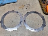
So I decided to take a swing at the clutch pack/clearances for the forward and direct drums. I did them both at the same time since the clutches/steels are the same size for both. I could go back and forth a bit on what steels I used.
Things that changed:
Forward drum got a better piston.
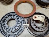
Direct drum was swapped out with a 4L80e drum assembly/sprag/etc.
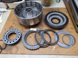
One thing that I saw was to use a steel at the very top when measuring clearance - easier for the feeler gauges to slide in between that steel and the pressure plate. Steel/clutch order doesn't really matter just to get the measurements for the entire stack.
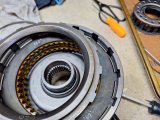
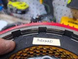
Also, as I've seen online, I use the visibility of the small ledge on the drum to get a general idea of where the clutch pack height is in relation to the final clearance. Just a ballpark - if the pack is way below the ledge, it's way too much clearance, and it's above the ledge, chances are that the clearance will be way too tight.
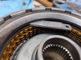
In the picture below, that ledge is just visible, so I know I'm in the ballpark. Top friction swapped with steel to make the feeler gauge measuring easier.
Here's a video from TW McDaniel that has a good overview of using that ledge as a general guide.
I'm using the TH400 Fast Facts linked from Nick's Transmissions for the clutch pack clearance/travel specifications.
Note that the clearances I came up with will also be checked against general builder consensus of which TH400 clutch packs are better set up as tight or loose. So my numbers may or may not be tweaked a bit.
Forward Drum .... clearance/travel range .030--050
I tried a couple of different setups and ended up with this selection.
The clearance is .042.
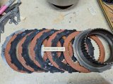
I was able to get the feeler gauge inside the hub to get the clearance measurement.
There's also no spring pack to get in the way.
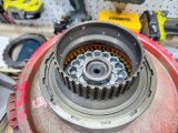
Direct Drum..... clearance/travel range .040-070
I had to remove the retaining spring assembly to get the feeler gauge in there to measure my clearances.
It was a no-go with it in place and there wasn't really room even if the gauges were bent.
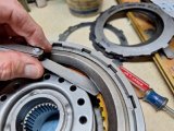
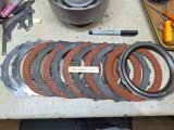
This was a first pass - huge amount of space, but it's mainly showing that the feeler gauges could be easily used once the spring assembly was out of the way.
With that initial large amount of space, I gave some thought to maybe using .080 frictions instead of the .092, and maybe some thinner steels to get six frictions in there instead of the standard five frictions. But then this isn't a mega horsepower build and I didn't think that the gain would be significant. With the new build, selected improvements, the dual feed, and slight changes to the valve body separator plate, this should be a good sturdy unit.
I added an extra steel at the wave plate and ended up with a clearance of .060.
Now for yet more research into what clearances the pros prefer. This was just a start.
I'm generally happy with the current results as my preference is to use thicker clutches/steels when possible for heat resistance.
Sometimes I feel like the dumbest guy on earth lol. I had mentioned that I ordered a couple of .060 wave plates for the forward and direct clutches. Today I was organizing the different clutch parts and a couple of the steels caught my eye. I have no idea why I missed it, but they were actually new wave plates - I now marked them as such. So looks like I'll have a couple of extra ones now


So I decided to take a swing at the clutch pack/clearances for the forward and direct drums. I did them both at the same time since the clutches/steels are the same size for both. I could go back and forth a bit on what steels I used.
Things that changed:
Forward drum got a better piston.

Direct drum was swapped out with a 4L80e drum assembly/sprag/etc.

One thing that I saw was to use a steel at the very top when measuring clearance - easier for the feeler gauges to slide in between that steel and the pressure plate. Steel/clutch order doesn't really matter just to get the measurements for the entire stack.

Also, as I've seen online, I use the visibility of the small ledge on the drum to get a general idea of where the clutch pack height is in relation to the final clearance. Just a ballpark - if the pack is way below the ledge, it's way too much clearance, and it's above the ledge, chances are that the clearance will be way too tight.
In the picture below, that ledge is just visible, so I know I'm in the ballpark. Top friction swapped with steel to make the feeler gauge measuring easier.

Here's a video from TW McDaniel that has a good overview of using that ledge as a general guide.
I'm using the TH400 Fast Facts linked from Nick's Transmissions for the clutch pack clearance/travel specifications.
Note that the clearances I came up with will also be checked against general builder consensus of which TH400 clutch packs are better set up as tight or loose. So my numbers may or may not be tweaked a bit.
Forward Drum .... clearance/travel range .030--050
I tried a couple of different setups and ended up with this selection.
The clearance is .042.

I was able to get the feeler gauge inside the hub to get the clearance measurement.
There's also no spring pack to get in the way.

Direct Drum..... clearance/travel range .040-070
I had to remove the retaining spring assembly to get the feeler gauge in there to measure my clearances.
It was a no-go with it in place and there wasn't really room even if the gauges were bent.

This was a first pass - huge amount of space, but it's mainly showing that the feeler gauges could be easily used once the spring assembly was out of the way.

With that initial large amount of space, I gave some thought to maybe using .080 frictions instead of the .092, and maybe some thinner steels to get six frictions in there instead of the standard five frictions. But then this isn't a mega horsepower build and I didn't think that the gain would be significant. With the new build, selected improvements, the dual feed, and slight changes to the valve body separator plate, this should be a good sturdy unit.
I added an extra steel at the wave plate and ended up with a clearance of .060.

Now for yet more research into what clearances the pros prefer. This was just a start.
I'm generally happy with the current results as my preference is to use thicker clutches/steels when possible for heat resistance.
Hmmm, I've got some rechecking to do. I started thinking about putting a friction directly on a wave plate - seemed to me that a friction needs a flat steel and that a wave plate could damage a friction.
The ATSG shows the clutch pack breakdown, and shows wave plates on some models. But the waves are in a separate outline under the main clutch pack, on second look they're not identified as a replacement for anything, just an addition. I'll get a picture later.
Worth pausing to confirm, I've got two packs so far that I've put the bottom friction over the wave plate.
Thunderbolt
Well-Known Member
My guess is you should not run a friction directly on a wave plate.
This build thread is great
This build thread is great

You're right!My guess is you should not run a friction directly on a wave plate.
This build thread is great
Nick's Transmissions was kind enough to respond to my question and yes, there needs to be a steel between the wave plate and friction.
The ATSG manual actually shows the correct pattern, I'll post a picture of it tomorrow. I think now I know why the original frictions were .080 vs the .092 in my kit. I anticipate needing to get .080 frictions- I'll go further with all this in the next post.
So I'm going to back up to the intermediate and start again. I think I've got a better handle on this now.
Edit - anticipating needing the .080 frictions, I want ahead and ordered 10 Raybestos .080 waffle and 5 Raybestos .080 smooth frictions from Sun Transmissions. Very reasonable cost. This gives me flexibility in the forward and direct clutch stacks. I already have both .080 and .092 waffle frictions for the intermediate.
Had I better experience, I would have waited to first disassemble the unit to see what was inside. I thought frictions were all the same thickness, but not so. About a $50 learning lesson.
Last edited:
ATSG Clutch Diagrams.....
I missed the boat here.
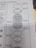
Note that you can leave the wave plates out of all the clutch packs but for this build I'd rather have the shift cushioning from keeping them. The unit should still have quick firm shifts.
Intermediate
The wave plate is shown as "per individual model" but it's in addition to the basic clutch pack. I replaced the bottom steel with the wave which was not correct.
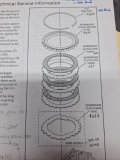
My setup
Direct
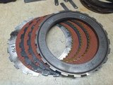
Same thing here. The wave doesn't replace the bottom steel.
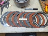
My setup that is actually (by accident) ok. Of course I'll double check the clearance again. Notice the steel between the wave and the friction. Remember that this is for the 4L80e drum that's got the molded piston - very different remaining dimension for the clutches from the TH400 drum. I used that steel to reduce clearance and happened to put it in the right place.
Forward
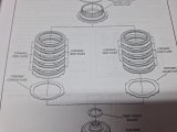
This one's a little different. Using the cushion plate vs wave plate isn't usually recommended- the cushion discs are fairly thin and can sometimes cause the bottom fiber to jam into the lower groove of the drum.
But note that ATSG shows use of the cushion as an extra, but the wave can be used without a steel. I think it's because the forward isn't a shifting clutch pack, it's engaged pretty much all the time.
This one needs a bit closer look as I still see more logic to separate the friction from the wave.
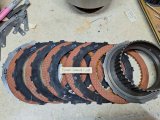
My setup which mimics the ATSG diagram. I just don't know why in this case the bottom flat steel is omitted. Still seems that the wave plate compressing directly onto the friction could damage or warp the friction.
After I receive the .080 frictions, I'll go back through the direct and forward clutches.
Since I have the .080 frictions for the intermediate, I can mess with that one now.
Edit - no, I can't. I need to add a steel between the wave and bottom friction. I ordered some thinner .076 intermediate steels, so between the different frictions and steels I'll be able to get the right clearance. No wonder builders keep a parts variety!
I missed the boat here.
Note that you can leave the wave plates out of all the clutch packs but for this build I'd rather have the shift cushioning from keeping them. The unit should still have quick firm shifts.
Intermediate
The wave plate is shown as "per individual model" but it's in addition to the basic clutch pack. I replaced the bottom steel with the wave which was not correct.

My setup

Direct
Same thing here. The wave doesn't replace the bottom steel.

My setup that is actually (by accident) ok. Of course I'll double check the clearance again. Notice the steel between the wave and the friction. Remember that this is for the 4L80e drum that's got the molded piston - very different remaining dimension for the clutches from the TH400 drum. I used that steel to reduce clearance and happened to put it in the right place.

Forward
This one's a little different. Using the cushion plate vs wave plate isn't usually recommended- the cushion discs are fairly thin and can sometimes cause the bottom fiber to jam into the lower groove of the drum.
But note that ATSG shows use of the cushion as an extra, but the wave can be used without a steel. I think it's because the forward isn't a shifting clutch pack, it's engaged pretty much all the time.
This one needs a bit closer look as I still see more logic to separate the friction from the wave.

My setup which mimics the ATSG diagram. I just don't know why in this case the bottom flat steel is omitted. Still seems that the wave plate compressing directly onto the friction could damage or warp the friction.

After I receive the .080 frictions, I'll go back through the direct and forward clutches.
Since I have the .080 frictions for the intermediate, I can mess with that one now.
Edit - no, I can't. I need to add a steel between the wave and bottom friction. I ordered some thinner .076 intermediate steels, so between the different frictions and steels I'll be able to get the right clearance. No wonder builders keep a parts variety!
Last edited:

