Here's some more tips Brian! Spread the word on this one I'm tired of seeing cars like ours assembled wrong.
I'm currently working on front end assembly/panel alignment and some fender vent aero mods I'll talk about in my next progress post. However I've been wanting to post about this problem unique to 70-73 bird's for years and today's the day!
Soapbox time!
70-73 Firebird front bumper and panel alignment.
I was a car guy teen when these cars were new and been researching/studying the bumper mounting , panel fitment, and the gaps for the past 25-30 years since my stepson got his first 70. Most of the 70-73 front ends on birds I see now have not been assembled/aligned correctly.
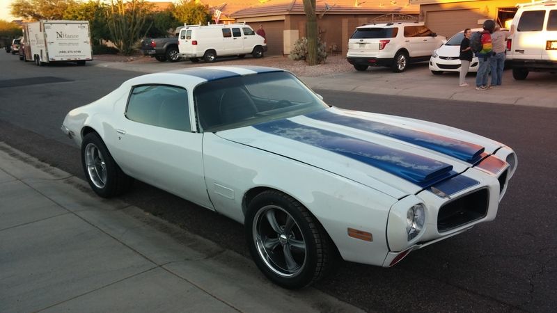
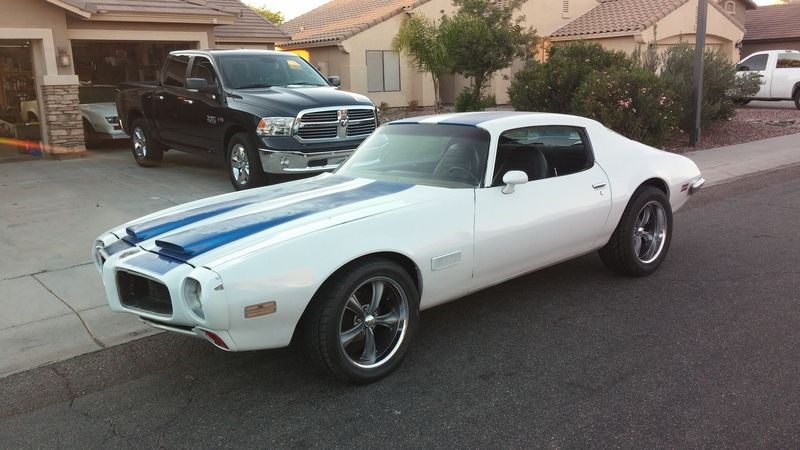
THE FRONT BUMPER IS NOT SUPPOSED TO TOUCH THE FENDERS.
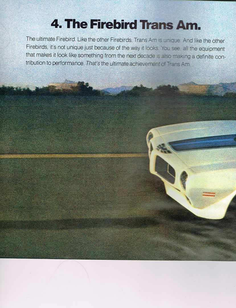
There is supposed to be a gap. It's wider than people want to see. Nobody likes it, not even the folks at Pontiac liked it when they were new. As you can see in the pics below the marketing people at Pontiac photoshopped (was that a thing then?) the gap between the fender and bumper right out of some of the pics in the 70 brochure because it looks "funny".
I see many beautiful cars where the owners have taken every step they can, buying NOS and correct original pieces for crazy prices just so they know they've got the right stamping's, date codes, etc. only to see the whole front end isn't panel aligned correctly. I feel bad for them because they just don't know. To me it's almost like hearing someone say they've got a "Big Block" Pontiac.
Soon after these cars were built they started getting in accidents etc.requiring bodywork and paint. IF the person took it back to the dealer the shop might have put the bumper back on correctly however many shops might just try to eliminate or reduce the gap if they even knew there was supposed to be a gap. It's been over 45 years since these cars were built and so even a body man who was in his 20's is probably retired even if he was a body man his whole life. So the folks who've been repainting these cars the past 30 years or so probably never even saw these cars new and don't realize the bumper isn't supposed to touch the fender. Most in the restoration/ body repair business now never saw these cars before they started being reassembled wrong so they try to split the differences and make the panel alignment/gaps look as good as they can with the bumper tight to the fender because they never even saw one with the correct gap. The misconception has gone on so long now that the majority of the cars I see now are assembled wrong and look kinda wonky but few realize why. The poor panel alignment is often attributed to the lower quality sheet metal stamping of yesteryear.
The subframe, bumper brackets, and bumper (as a solidly bolted structure) were isolated from the unibody,fenders, core support, splash pan, and core support/latch brackets (again solidly bolted structure) by
8 rubber bushings allowing the 2 sections to move slightly independent of each other. 4 rubber body mounts, 2 rubber core support mounts, and the 2 rubber upper bumper mounts. This allowed movement of the two structures individually and so a gap was needed between the fenders and bumper to prevent the bumper being deformed on uneven surfaces and when the car was jacked up. When the first urethane bumpers arrived on the 69's they put a rubber gasket between the bumper and body and people didn't like it so in 70 they reduced the gap and left it open.
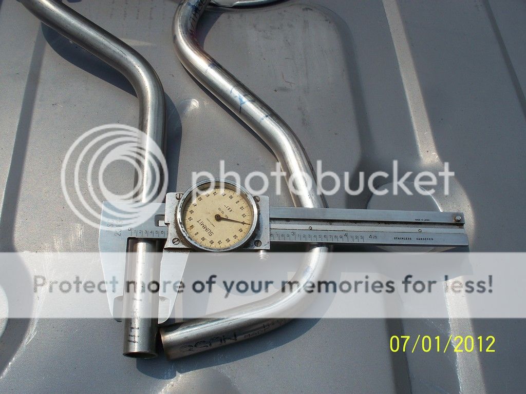
The gap needs to be roughly 3/16" - 1/4" on most of the cars to get everything lined up as well as can be keeping in mind that factory stamping and tolerances of early 70's cars was nothing like today's cars.
In this first page from the brochure you can see that the marketing guys made the gap disappear on the passenger side of the upper image while it is clearly seen on the lower image.
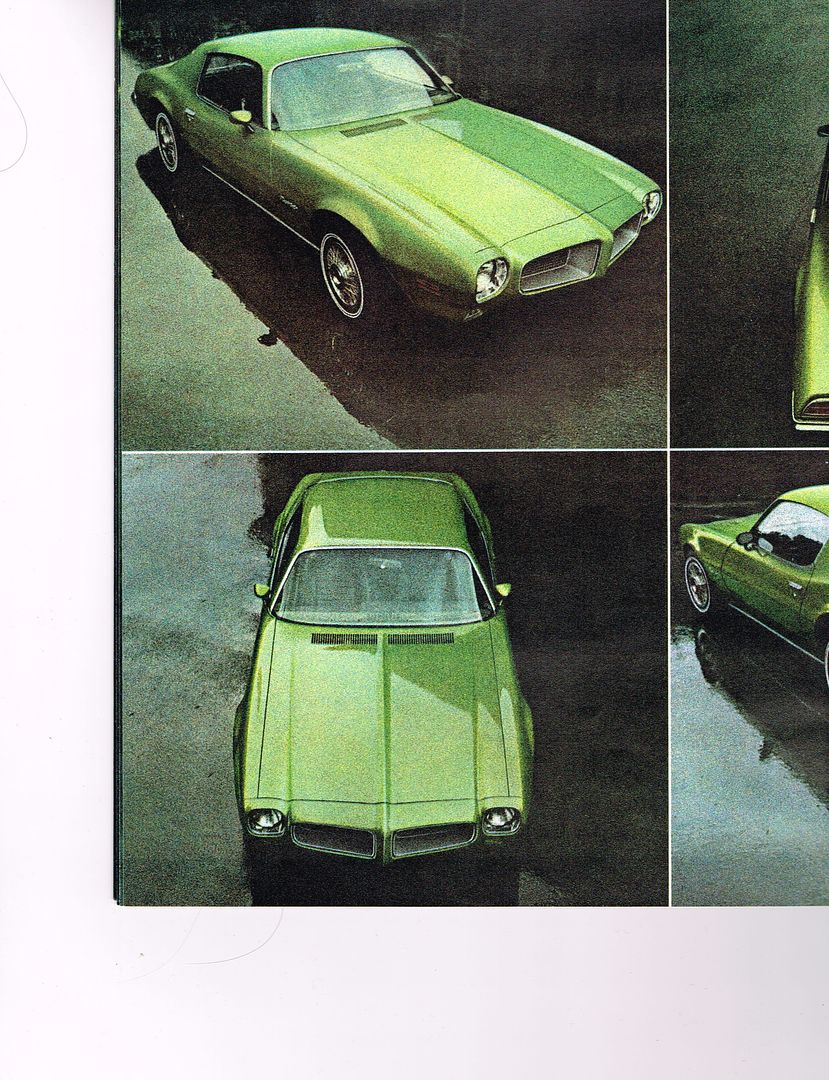
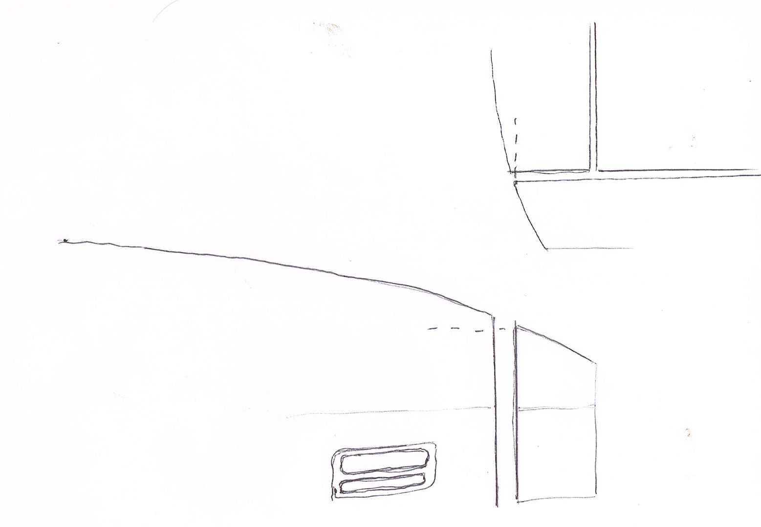
On the page below you can clearly see the gap, note the front of the hood lines up with the front of the fender.
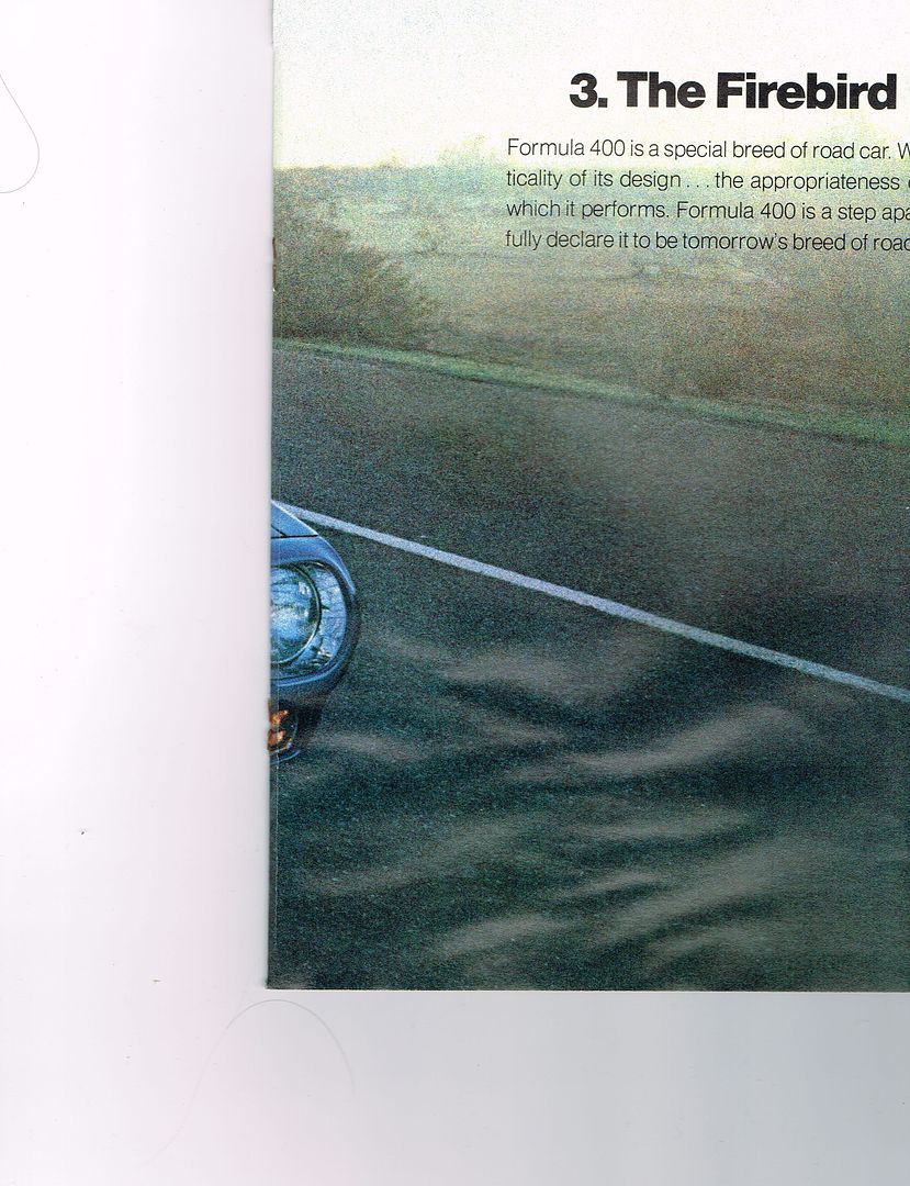
Apparently the marketing folks figured the gap showed up waaay too much on a white car.
Pic below is exaggerated to show how the body lines and fitment get screwed up. Think of it as taking a slice out of a cone and then trying to mate the remaining pieces. The gap needs to be roughly 3/16" - 1/4" on most of the cars to get everything lined up as well as can be keeping in mind that factory stamping and tolerances of early 70's cars was nothing like today's cars. When folks try to have the bumper touch the fender it causes problems aligning the front end sheet metal. Several problems arise and folks try to juggle all the pieces to minimize the affects but the pieces won't line up well so the common thought is "They just didn't make the cars very good back then"
These are the most noticeable effects of trying to have the bumper touch the fender.
1. The hood sticking too far back toward the windshield and sticking up even when the hinges are adjusted to the max trying to lower it.
2. The middle of the hood arches above the fender. Commonly attributed to the "Formy arch" or lousy hood springs. It's actually also caused by the hood being too far back and the arch of the hood not matching the arch of the fender.
3. When the bumper is tight to the fender people pull the fenders in toward the hood trying to get the points on the top of the bumper to line up with the top of the fender. this causes too small of a gap to the hood and often the car gets assembled without the side rubber hood bumpers because they push the hood up causing the mid hood arch to be off even more with the fender.
4. When the fenders are pulled in, the bottoms of the fender get pulled in afterward when trying to get the side of the fender to curve like the side of the bumper. Then the splash pan seems like it's too long.
5. The side body line will be off because when pulling the bumper tight to the fender it also gets raised to have the top of the bumper flush with the top of the fender. So the bumper body line ends up slightly higher than the fender body line. Sometimes this gets "fixed" during bodywork with filling/blocking if the bumper is on the car at the time.
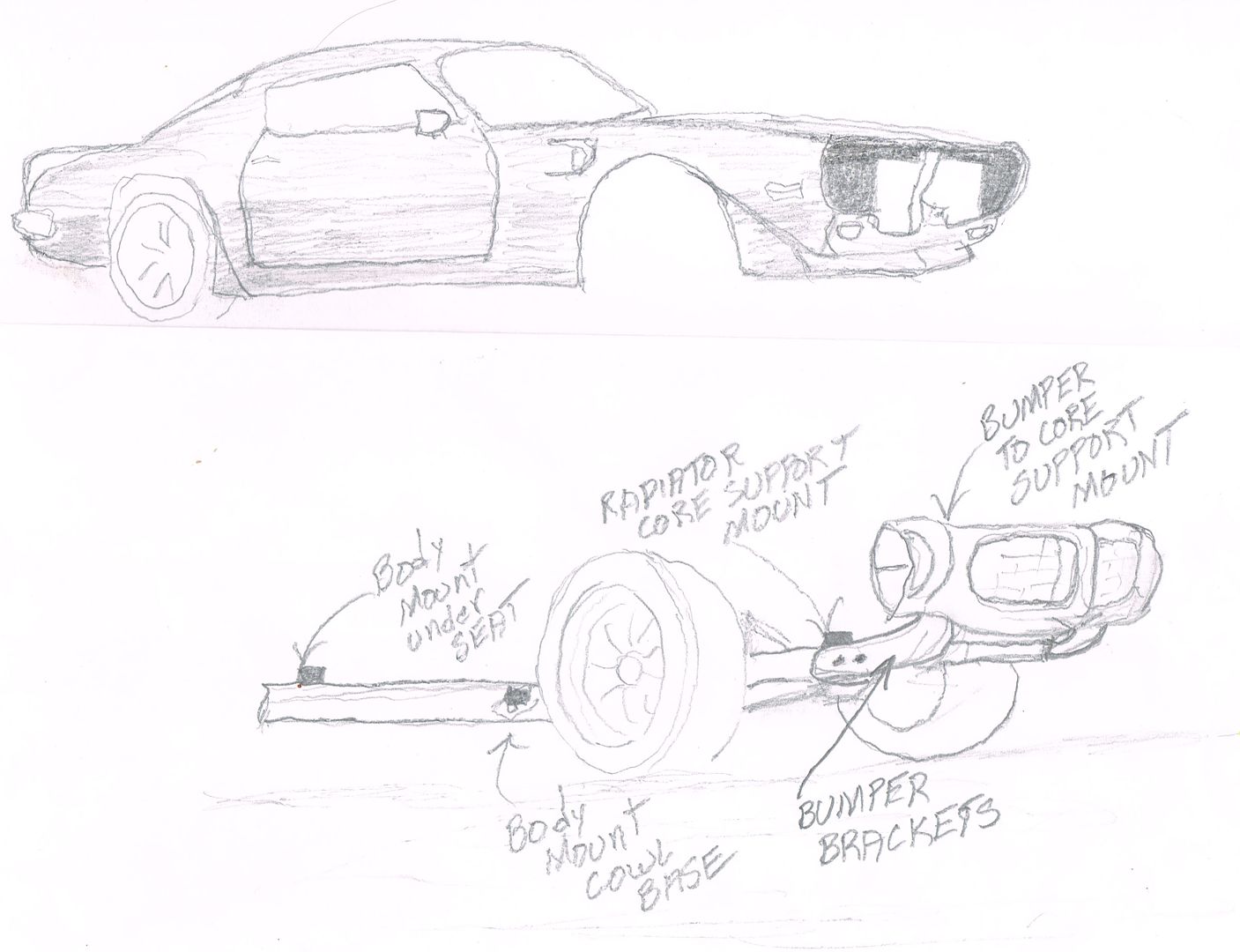
The crude sketches below show how the car is built. The main portion of the car is comprised of the unibody along with all the front sheet metal bolted solidly together (excluding hood because it's on hinges). It includes the fenders, inner fenders, inner fender extensions, core support, latch support, and splash pan. The smaller section includes the subframe, bumper brackets, and bumper (with lights and grills) bolted solidly together with the front suspension and steering attached. A third section is the engine/transmission bolted solidly together and "floating" on rubber mounts over the subframe.
The gap was necessary to allow the two main sections of the car to move a little independent of each other without damaging the sides of the bumper and paint on the leading edge of the fenders.. Even if you use solid body mounts the bumper still needs the gap to get the panel alignment correct because it was designed knowing the gap was necessary and the body lines needed to appear to flow over the gap.
Came across some pics on another forum that demonstrate how
NOT to line up the bumper. This is a classic example of what happens when folks try to have the bumper touch the fender and don't know what they're doing is wrong. As an added bonus it also shows how the more flexible formy hood reacts. Don't worry, I'm not picking on someone's car that's being used like this. It's already apart for restoration.
The bumper below looks like it was installed while the car was on jack stands or a lift and they tried to have the bumper touch the fender. Then when they dropped the car on the ground the result was popping the paint on the drivers side of the bumper and a funny gap on the passengers. The hood was moved back so there would be a gap and the hood corners by the windshield probably got sanded off because they looked funny. The fenders were pulled in toward the hood in front trying to match the bumper causing the raised section of the Formy hood mid fender. Also notice the side body line of the bumper is now too high compared to the fender.