Unforgiven
solid fixture here in the forum
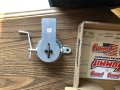
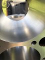
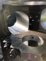
the internal air passages look to be very restrictive in the picture, far smaller than the area of the carb base plate opening
Thank you Grumpy... I thought the same thing but I have been known to be wrong.
the internal air passages look to be very restrictive in the picture, far smaller than the area of the carb base plate opening
It may have porting potential.https://www.aussiespeedshop.com/pro...4-carb-supercharger-adapter/?wmc-currency=USD
IF I decide to use two Converted Predator carbs... this is the adapter I was looking at.
I don't know if the area in the adapter looks large enough to flow well. It looks small.
Guy's I realize that I am all over the board with my fuel delivery... I am just looking at different options at this point in time.
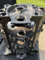
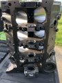
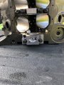
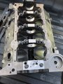
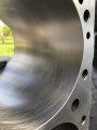
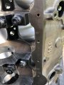
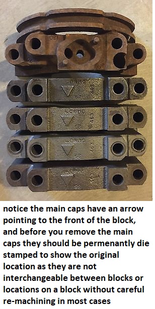

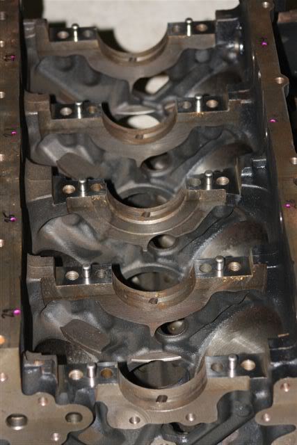
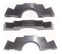
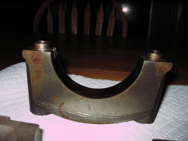
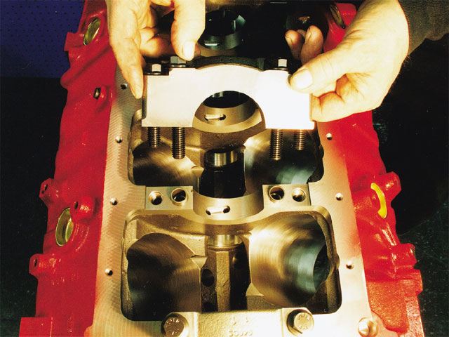


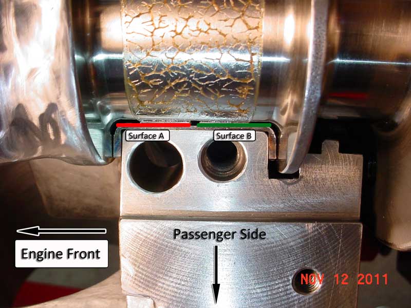
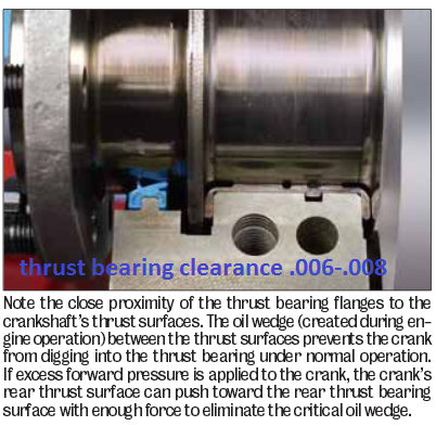
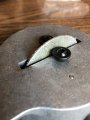
to me it looks like the rear main caps lower thrust bearing surface,
is a recessed couple thousands more to the rear of the block,
than the matching upper block thrust bearing surface,