Unforgiven Project

wow! Thats a damn impressive update and some great, related pictures!
congrats on the significant progress!
and yes youve very easily increased engine efficiency too a noticeable degree with the removal of that port flow restriction
 
Last edited:
Engine Porn, I love it!!!

That was a lot of material to remove from the intake, surely that will make a sizeable difference.
 
Thank you Men!
I ended up porting all the way into the plenum . It was scary cause the manifold was a lot thinner the closer I got toward the plenum.
But I think it will breath now..:)

I forgot to mention that all that material was on the topside of the port..The intake was upside down when I took that pic
 
Those tires would be 18.4 x 16.1 TITAN 's
They are agricultural tires normally found on Combine farm equipment.
They are around 44" tall ... and weigh 225lbs including the wheel.. Each.
It takes lots of torque to spin those puppies!
The suspension has to be modified to be able to withstand the abuse also.
I have custom designed and built the entire under carriage of this truck.
It uses 1410 U-Joints.
2 1/2 ton military axles
Transfer case is a special reverse front rotation matched with the axles also.
This is because the ring gear in the front axle is located on the opposite side in the center chunk
from any other axle. If you where to use a regular Transfer case ... the front axle would spin in reverse while the rear axle spins forward.
I have added shackles to each end of the front leafsprings for a softer ride. In order to do this, I had to fabricate a parallel 4 link control bar suspension.
The steering has been removed and replaced with a FULL hydraulic control system.
You can steer this beast with your little finger!:D

Thanks for letting me know.
 
I bought another timing pointer from Summit , and it's mount surface pad is short...So I made an aluminum extension pad on in order to use it.
I am fortunate to have a CNC milling center that I can whip one up really quick! :D

IMG_0482.JPG IMG_0483.JPG IMG_0484.JPG IMG_0485.JPG

I like to use a paint marker on the "0" line and a different color on the "36" line for a quick reference when I set or check timing.

So.... I made another smooth move yesterday :bhow:
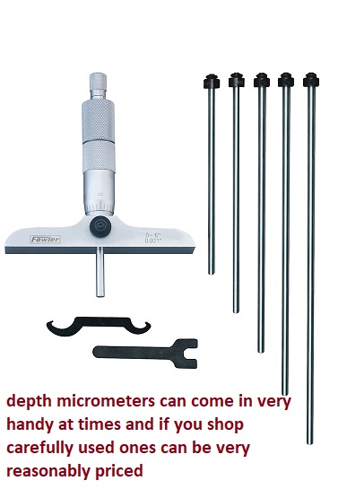
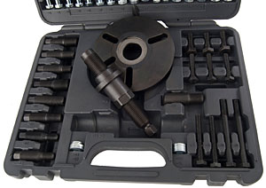
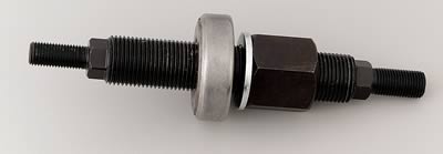
... I had rented a balancer install tool and installed the balancer ...so I thought!
I returned the tool yesterday at lunch so I could try to keep organized . What I forgot about , was I did not seat the balancer because I needed to install the pulley's and make sure it all lined up. WELL.....They didn't! And there I stood last night without that install tool!
BUT... The pointer looked NICE!!!:)
So I will return to the parts store and rent the damn thing again today!:facepalm:

Luckily... AutoZone 's rental policy is you buy the tool and return it for a refund. The rental cost is ZERO.
 
if you buy a damper/installation/removal tool get one thats universal,
with interchangeable threaded tip inserts,
yes you will eventually over tighten the tool and bust the REPLACEABLE INSERT,
these are generally available separately for about $15 each individually
(call the manufacturer)
(don,t bother too ask...
yeah Ive screwed that up a couple times in the last 55 years,
and had to order spare replacement inserts)
use of a dial caliper and careful measurement tend to avoid over tightening the tool,
and your almost certain to strip crank snout threads if you think you can use the damper retention bolt,
to pull the damper onto the crank snout,
the tool allows all the threads to bear the stress loads,
before the stress is applied vs only a few with the retention bolt used.

522251160.jpg

13cal.jpg


balancerdepth.jpg


918999.jpg

http://www.jegs.com/i/JEGS-Performance-Products/555/W89711/10002/-1

harmonic3.jpg

http://www.tavia.com/cat12.html#1

tav-08200_w.jpg


https://www.amazon.com/gp/product/B000F5LIW4/ref=oh_aui_detailpage_o01_s00?ie=UTF8&psc=1
index.php


https://www.otctools.com/products/harmonic-balancer-pullerinstaller-set
read through all links and sub-links
http://garage.grumpysperformance.com/index.php?threads/harmonic-balancer.3554/#post-53706


http://garage.grumpysperformance.com/index.php?threads/what-damper-flywheel.6026/#post-21582

http://garage.grumpysperformance.com/index.php?threads/don-t-beat-that-damper.83/#post-14101

http://garage.grumpysperformance.com/index.php?threads/damper-honing.4975/#post-13912

http://garage.grumpysperformance.com/index.php?threads/damper-tool.223/#post-8024

https://www.dieselarmy.com/engine-tech/engine/how-it-works-viscous-dampers-a-k-a-harmonic-balancers/

https://www.dragzine.com/tech-stori...ers-are-crucial-to-the-health-of-your-engine/

http://www.laskeyracing.com/shop/harmonics.htm

https://fluidampr.com/how-a-fluidampr-works/

http://www.dieseltechmag.com/2009/02/dt-tested-fluidampr-performance-damper

https://motoiq.com/project-golf-r-mkvii-fluidampr-test/3/

http://garage.grumpysperformance.com/index.php?threads/cheap-damper-ballancer-source.279/#post-1673
 
Last edited:
I am fortunate to have a CNC milling center that I can whip one up really quick! :D
Do you have to point that out every chance you get!!! :( hehehe!

Is that pointer going to be hard to see, it looks like it's under the water pump somewhat???
 
Do you have to point that out every chance you get!!! :( hehehe!

I actually threw that out there to get a reaction from you Rick! :D:)
I have'nt heard from a few of you guys lately.... Summertime keeps us all busy I guess.


As far as the pointer.. I was wondering the same thing. But , I have to press the balancer another 3/8" back. This would put the needle
closer to the etching marks also. It was hard to see the stock pointer for sure!
That is one of the reasons I like to highlight the "0" mark and the "36" mark for a quick reference.
As of now... It looks like I will be able to see alot more of the balancer.
With your connections, couldn't you scribe new timing marks that are in a much better position
for viewing straight on. They might have to be on the other side of the engine since the alternator
will be in the way if you go lower on the driver side.
 
Maybe you could just move the pointer to the other side and use cylinder #2 to check timing. That
way you could use the same timing marks only they would be 90° CCW looking at it from the front
of the engine.
 
Maybe you could just move the pointer to the other side and use cylinder #2 to check timing. That
way you could use the same timing marks only they would be 90° CCW looking at it from the front
of the engine.

He would get confused like I would if he done that. Left is right and right is wrong is the way it would wind up--only opposite.
 
With your connections, couldn't you scribe new timing marks that are in a much better position
for viewing straight on. They might have to be on the other side of the engine since the alternator
will be in the way if you go lower on the driver side.

The alt is up high on the passanger side..
The aluminum bracket you are seeing is for the power steering pump

But thats an idea that I never would have thought of.
 
I remember the only thing that was blocking my view ... was that really wide stock timing plate.
It covered the entire surface of the balancer, which made me come up with the painted line idea on the front of the balancer.
but as far as seeing down onto the balancer... I think this new one is going to be the ticket.

Also my radiator hoses are routed different also, the radiator is in the bed. I have a 1 5/8" emt pipe running along the frame
to the engine bay, then it 90's up for about 4" for the hose connection. I actually relocates the hose from blocking the balancer
view.
 
He would get confused like I would if he done that. Left is right and right is wrong is the way it would wind up--only opposite.

It would be better for me to put the mark on the bottom.... cause my truck sits 9' in the air. Then i could just sit in my office chair
that I got from work (where I have access to all those CNC machines), And slide myself under the motor for an easy view of the balancer!:rofl::cwl:
 
How I do timing pointer. http://garage.grumpysperformance.com/index.php?threads/timing-tabs-and-indicators.1015/#post-49812

TIP: Apply a ring of Permatex to the inside of the harmonic balancer hub before installing on the crank to prevent an oil leak, especially along the keyway slot. Place the Permatex about 3/8" further in than where the end of the snout will end up. It will roll into a bead as it is pressed on. Use anti-seize on the snout. Be sure to oil the seal and make sure that the lips of the seal do not get folded in. A dental pick works well to carefully straighten it out. Then use you finger to smooth the sealer, if you want to. Mike.

index.php
 
I had a very very Bad night last night.
I installed the pulleys and discovered that they where off by about 1/2"
My buddie was out of town when I called him for a second set of eyes... He told me to walk out of the barn and DON'T touch
anything .... ( he could tell I was fustrated)
I should have listened to him......

I felt that something was stopping the balancer from going in further... so I removed the water pump and timing cover to expose the chain set.

Well in my fustration... I forgot that on Friday I installed my new 1 piece pan seal, and began to remove the timing cover. I TORE THE SEAL IN HALF!

I deserved it!! I should have just walked away and relaxed!

ANYWAY.. I reinstalled the balancer after checking that the gear set was properly installed and seated.

The issue is: The pulleys won't line up... They are the same pulleys that was on the old motor.
The blower pulley lined up before on the old block, and it is showing that the lower pulley needs to be pushed toward the block about 1/2"

I have checked and found the new balancer is the same overall length compared to the new balancer. The balancer is seated as far onto the
crank as it will go...it is up against the timing gear, which is seated against the crank shoulder.

Everything is showing me that I need to machine down the back off the lower blower pulley and find some off set accessory pulleys.
Do you guys have any ideas of what I may not be see'ing.

I am very fustrated cause the only thing new is the block , the crank , and the balancer.. and it measures the same as the old one for length. It just has a smaller O.D than the old one.

Everything lined up on the old motor!??

IMG_0489.JPG IMG_0492.PNG
IMG_0490.PNG IMG_0491.PNG
 
have you measured the distance from the crank/damper shoulder to the front main cap?
if you have access to a decent lathe Id consider cutting a 1/2" out of that dampers rear extension length
that slides over the crank snout, obviously look that option over, it will have near zero effect on balance but key ways might be effected
 
Grumpy!!!
I was hoping you have ran into this situation before.
I thought about that but I was not sure about it.
My thought was to turn the rear extension... but I was wondering if it would effect the overall weight of the balancer enough to cause damage to the front bearings. the whole rotating assembly was balanced within .2 gr

The other problem with turning it is: I would only be able to turn off about .225 before the back of the balancer would rub on the timing cover.
 
have you measured the distance from the crank/damper shoulder to the front main cap?

No I have not yet. But from what I see the timing chain and gears cannot go back any further or the gear on the cam will rub on the block.
The gears are lined up straight .
I am thinking that I may have to machine some off the back of the lower blower pulley to allow it to line up with the upper.
That would cure that situation but it leaves me with the power steering pump and alternator crank pulley to be replaced.
 
In a nut shell:
There is only .225 space between the balancer and timing cover.
The lower blower pulley needs to be moved in .500
The lower V bellt pulley needs to move in .437
 
Back
Top