You are using an out of date browser. It may not display this or other websites correctly.
You should upgrade or use an alternative browser.
You should upgrade or use an alternative browser.
Electrical Wiring for a TBucket
- Thread starter Indycars
- Start date
NOT A TA
reliable source of info
Indycars said:
The grey wire is for grounding the tach to set the RPM Limiter.
I anticipate showing the tach wiring in the instrument wiring diagram.
OK, cool. Carry on!
I know it would be easy to ask MSD, but I like to see if I can figure out the
answer before I call them to confirm. What size fuse should be used to protect
the MSD coil?
I only need to protect the primary side, so ...... I = E / R
12.5 / .355 = 35.2 amps or 40 amp fuse
Sure seems high, so what could be wrong??? Input please!!!
Attachments


NOT A TA
reliable source of info
It only takes a small wire to power coils so a 40 amp fuse is probably too big. The SS and other MSD coils I've installed were always in conjunction with versions of the MSD 6 box so I haven't wired one direct as you are planning. I'm not a math guy at all so if I were going to run a coil wired as you are planning I'd call the MSD tech line.
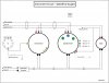
Instead of having just one drawing, I'm going to have two drawings for my
instruments. One for the SpeedHut gauges and one for the AEM gauges.
Below is the drawing for my SpeedHut gauges .....
The gauges come with connectors already installed except for the turn signal
and high beam indicators on the speedometer. Also the cruise control wire I
had added from the stock configuration.
Attachments
mathd
solid fixture here in the forum
RickIndycars said:
I know it would be easy to ask MSD, but I like to see if I can figure out the
answer before I call them to confirm. What size fuse should be used to protect
the MSD coil?
I only need to protect the primary side, so ...... I = E / R
12.5 / .355 = 35.2 amps or 40 amp fuse
Sure seems high, so what could be wrong??? Input please!!!
You can't use the primary resistance for the math because the primary side is an inductor working ac current not a resistor. When working with inductor you need to use the primary impedance (so we need to know the operating frequency of the circuit with the inductance to figure the inductive reactance so you can then use the I = E/R formula) that wil be good for unloaded circuit not the best way to figure it out for what we are trying to do.
The primary of that coil is probably not running at 13.8 volt anyway?
The turn ratio is 70:1, so for 40k volt you need 500 volt on the primary Sounds crazy eh?(magic happen when an inductor is switched on and off, usually the duty cycle is what set the coil output voltage on a PWM dc-dc converter,, but distributor are alot simpler), So in fact the primary side of the coil and circuit is some kind of really simple boost converter
") 13.8v input but coil primary run at about 450v~
13.8v input but coil primary run at about 450v~So be carefull with the primary wires you could get a surprize if you touch them at the wrong time
Without going into technical details..
Make it simple.. use the spec we have
70:1 turn ratio, peak output current 300ma on the secondary side... so 300ma X 70 = 21 peak amp on the primary side.
So yes using a 20amp fuse seem about right. (you may think, make it bigger so it not blow at peak current @ 21A) but this is a peak AC value, if you figure the real constant power the current is not gonna be 20A total its probably going to end around 8 amp.
Here is how, say we have 450v peak volt at the primary side, we expect 21 peak amp, so we find the primary load impedance (450/21)=21ohm.
We rms the 450 volt v-p-p = 159 Vrms.. now we find the real current.. 159/21 = 7.57 amp (or a bit more, if you add coil current and some loss and how good or bad the circuit is designed)
.So i guess a 10-15 amp fuse should do it.
Blaster coil are rated at 450v input, and my msd 6-al box around 8amp or 1amp per 1000rpm.. so we are within spec.
Also should use 13.8v when doing car math not 12.5, its the norm for car elect.
Most car electronic is designed to run at 13.8vdc +/- 15% negative ground.(between 11.7 and 15.8volt)
Seem clear? questions?
BTW am back on the board, i was stupid and had a feeling my advice was useless here.. so i left for a couple month, tryed to do ham radio repair but am too picky, i want to repair only yaesu or icom because i like the part department and service manual haha.. Anyway, next winter i think am going to start a snow blowing business
.First let me say it's great to have you back Mathieu !!!! I knew you would miss
me too much to stay away for ever!!! :roll:
I know of inductance and reactance, but that's about it ..... not enough to include
in my analysis. I upped the voltage, just not enough, good to know the norm for
calculations is 13.8 volts. Thanks for that great explanation with some actual
number examples.
Hope you plan on sticking around and helping out :!:
mathd
solid fixture here in the forum
Yes i plan on staying around. Its so hard to find a great place and great people like we have here.. Can't live without itIndycars said:
First let me say it's great to have you back Mathieu !!!! I knew you would miss
me too much to stay away for ever!!! :roll:
I know of inductance and reactance, but that's about it ..... not enough to include
in my analysis. I upped the voltage, just not enough, good to know the norm for
calculations is 13.8 volts. Thanks for that great explanation with some actual
number examples.
Hope you plan on sticking around and helping out :!:
.
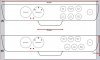
I want to get some opinion on the look of two different gauge layouts for my
dash. It's certainly no big deal, but if someone would like to express an opinion
which one they like ...... Dash (A) .... or Dash (B).
Comments and votes greatly appreciated !!!
Attachments
I like (B) a bit better but why are all the smaller gauges all shifted so far to the pass side and clumped there?
I think you could shift the whole group toward the other gauges and spread them out slightly more
I think you could shift the whole group toward the other gauges and spread them out slightly more
grumpyvette said:I like (B) a bit better but why are all the smaller gauges all shifted so far to the pass side and clumped there?
I think you could shift the whole group toward the other gauges and spread them out slightly more
The steering wheel blocks the view of the dash center. If I move the small gauges
towards the center, then I will have to lean over to view the first few gauges.
Remember they are digital, so there won't be any parallax error. I just need to
read the number.
The dash is going to be tilted out at about 20°(facing up), but the plan is also to
make it adjustable. I'm worried about reflection at 20°, hence the reason to
make it adjustable. Time will tell if I can pull off the adjustable part thou.
mathd
solid fixture here in the forum
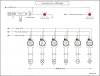
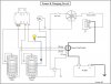
Just one thing with the power and charging circuit.
Should add a diode to stop +12v supply from the alternator idiot lamp (say anode toward the bulb and cathode toward the alternator if you put it between the bulb and alternator, or between the switched power and bulb do anode toward the switched power and cathode toward the bulb)
This thing not only ground the bulb when its not charging.. it also put out a +12v when its charging.
That can cause problem when shutting off the ignition/engine. (in some case where the switched power current draw is low the engine keep runing for a few seconds or more even with key off). I have seen engine refuse to shut off because of that, not fun to have an engine running for minutes with key off(ignition wired direct to battery loll)..
For the dash i vote for B, and move them to the left a little closer or have 2 of the small gauge moved to the left side of the big one or all of that.
Should add a diode to stop +12v supply from the alternator idiot lamp
(say anode toward the bulb and cathode toward the alternator if you put it between the bulb and alternator, or between the switched power and bulb do anode toward the switched power and cathode toward the bulb)This thing not only ground the bulb when its not charging.. it also put out a +12v when its charging.
That can cause problem when shutting off the ignition/engine. (in some case where the switched power current draw is low the engine keep runing for a few seconds or more even with key off). I have seen engine refuse to shut off because of that, not fun to have an engine running for minutes with key off(ignition wired direct to battery loll)..
For the dash i vote for B, and move them to the left a little closer or have 2 of the small gauge moved to the left side of the big one or all of that
.NOT A TA
reliable source of info
Rick, I vote for B and would consider something like these as a possibility to angle the gauges toward the driver. http://www.summitracing.com/parts/ATM-2234/
Mathieu, good idea on the diode and "Hooray!" we have a math guy back aboard.
Mathieu, good idea on the diode and "Hooray!" we have a math guy back aboard.
mathd said:Just one thing with the power and charging circuit.
Should add a diode to stop +12v supply from the alternator idiot lamp
This thing not only ground the bulb when its not charging.. it also put out a +12v when its charging.
That can cause problem when shutting off the ignition/engine. (in some case where the switched power current draw is low the engine keep runing for a few seconds or more even with key off). I have seen engine refuse to shut off because of that, not fun to have an engine running for minutes with key off(ignition wired direct to battery loll)..
For the dash i vote for B, and move them to the left a little closer or have 2 of the small gauge moved to the left side of the big one or all of that
Good point, the diode is shown below in the updated version of the drawing.
That's a new idea I hadn't thought of before! I will take a look at moving two
of those small gauges to the other side and see how it looks. The steering
wheel may prevent that location dues to visibility thou.
Attachments
mathd
solid fixture here in the forum
Wiring look good nowIndycars said:mathd said:Just one thing with the power and charging circuit.
Should add a diode to stop +12v supply from the alternator idiot lamp
This thing not only ground the bulb when its not charging.. it also put out a +12v when its charging.
That can cause problem when shutting off the ignition/engine. (in some case where the switched power current draw is low the engine keep runing for a few seconds or more even with key off). I have seen engine refuse to shut off because of that, not fun to have an engine running for minutes with key off(ignition wired direct to battery loll)..
For the dash i vote for B, and move them to the left a little closer or have 2 of the small gauge moved to the left side of the big one or all of that
Good point, the diode is shown below in the updated version of the drawing.
That's a new idea I hadn't thought of before! I will take a look at moving two
of those small gauges to the other side and see how it looks. The steering
wheel may prevent that location dues to visibility thou.
What kind of steering wheel is that?, i mean from the sounds of it. it look very big
.Angle gauge look to be a good idea too, i see it as usefull and aesthetic improvement :!.
NOT A TA said:Rick, I vote for B and would consider something like these as a possibility to angle the gauges toward the driver. http://www.summitracing.com/parts/ATM-2234/
Mathieu, good idea on the diode and "Hooray!" we have a math guy back aboard.
Not sure how they will work with a dash that's nearly one inch thick. Probably
have to buy a set to see how well they work. It would be nice if the gauges were
pointed at the driver.
mathd said:What kind of steering wheel is that?, i mean from the sounds of it. it look very big
Angle gauge look to be a good idea too, i see it as usefull and aesthetic improvement :!.
The steering wheel is made by Moto-Lita in Britian. It measures 13 inches
center line to center line.
https://www.moto-lita.co.uk/default.aspx
Below is a rough approximation of what I see, there maybe room for some
gauges around the big 4 inch gauges.
Attachments

busterrm
solid fixture here in the forum
I agree with Grumpy, but why put the clock that far away, why not move the smaller gauges toward the driver's side and put the clock just next to the big gauges. JMOgrumpyvette said:I like (B) a bit better but why are all the smaller gauges all shifted so far to the pass side and clumped there?
I think you could shift the whole group toward the other gauges and spread them out slightly more