once the engines solidly supported in the car frame and properly connected,
to its sub support electrical,exhaust and cooling systems theres no reason NOT,
to fire it up and check for correct function,
look for oil leaks,
break in the rings,
set the ignition timing,
set the carb floats,
verify oil flows liberally from all rockers,
check fuel pressure,
and check the valve train
and do the valve adjustments
and initial tuning!
you might think of having the engine installed like that as a rudimentary,
engine test stand
related info
http://garage.grumpysperformance.com/index.php?threads/engine-test-run-stand.930/#post-40783
http://garage.grumpysperformance.co...ear-articles-you-need-to-read.282/#post-52016
http://garage.grumpysperformance.com/index.php?threads/cam-break-in-procedure.130/#post-160
Cam Break-in Procedure
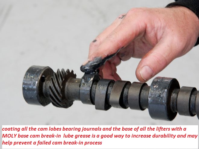

MOLY adds a great deal of lubrication to sliding metal surfaces , as it embeds in the micro fissures in the metallic surface's
• Have a high quality service manual available, such as the factory service manual, or the vehicle specific manuals published by Chiltons, Motors, or Haynes. You will need these for the basic information regarding engine disassemble and reassemble along with the torque settings for the various fasteners.
• Read and understand the manual completely, along with these instructions before you begin working. We highly recommend you also have the assistance of a knowledgeable friend to assist you, especially during the initial fire-up and break-in period.
In addition to the normal installation procedure, installing a performance camshaft requires you to check for several extra items to insure long life and optimum performance.
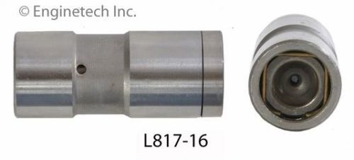
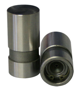
• New Lifters Are A Must- There is no such thing as a good used lifter! Any flat faced lifter establishes a wear pattern almost immediately with the cam lobe it is riding on and cannot be used on any other cam lobe, let alone a different cam. Should you have a need to disassemble the engine, make sure you keep the lifters in order so they go back on to the exact same lobes.
• Valve Spring Pressure and Travel- We highly recommend purchasing the matching valve springs recommended in our catalog. This insures you will have the proper pressures, both closed and open, and sufficient travel to get the maximum rpm, performance and life from your new cam.
• Piston to Valve Clearance- While many performance cams will work just fine with stock pistons, there are many factors that effect your engine and the clearance available. Things such as factory tolerances, normal machine work such as head and block surfacing, aftermarket components such as cylinder heads, higher ratio rocker arms, etc. all effect your engines ability to handle a performance camshaft.
• Valve Train Interference- In addition to valve spring travel and piston-to-valve clearance, a commonly overlooked area is that of retainer to seal clearance. The other common area of interference is rocker arm to stud clearance along with rocker arm travel. The best way to check these is by physically opening both a intake and an exhaust valve on each cylinder head to the gross lift of the cam plus and additional .030". It is easiest to do this by pressing down on the rocker arm with one of the many tools available. Do not simply rotate the engine to the maximum lift point for a given valve. This does not work when engines are hydraulic lifter equipped, or even allow any margin of safety when you are using a mechanical lifter cam.
• Valve Adjustment- The easiest way to insure proper adjustment is to adjust the rocker arms as you install them, one cylinder at a time. Adjust the intake valve as the exhaust valve is just starting to open and adjust the exhaust valve when the intake valve is almost closed. It is simplest to do this with the intake manifold off and watching the lifter’s movement.
• Hydraulic Lifter Valve Adjustment- All engines, regardless of manufacture, require correct valve adjustment. Some engines, such as Chevrolet V-8’s, are equipped with stud mounted rocker arms can easily be adjusted to compensate for changes incurred during engine assembly. Never just torque the rocker arm into place and assume that the lifter preload will automatically be correct. Various engine manufacturers use multiple length pushrods, shims, and spacers to compensate for changes in preload. Hydraulic lifters cannot compensate for all changes. Ideal lifter preload is .020" to .080". Do not attempt to fill the lifters full of oil prior to installation. They will fill automatically once started and manually filling them makes adjusting the preload a difficult task.
• Mechanical Lifter Valve Adjustment- Adjusting mechanical lifters should be done the same way as outlined above, one valve at a time. For an initial setting, we recommend .003" to .005" than listed on the cam’s specification card. Once broken in and with the engine fully warmed up, re set the rocker arms to the cam’s specification sheet.
• Installation Lubricants- All flat faced (non-roller) camshafts require the use of high pressure lubricant supplied with your Erson cam on the bottom of the lifters, the lobes of the cam and on the distributor drive gear. Do not use this lube on the tips of the pushrods, the sides of the lifters or on the rocker arms. Use a quality oil when installing roller tappets.
BEFORE YOU TURN THE KEY
• Fill All of the Engine’s Fluids- Using a minimum of a SAE API SD, SE or better fresh clean mineral based oil, fill the engine to the proper level. Do not use synthetic oil during break-in. Fill the coolant system and follow the instructions on purging air from the system. With carburetor equipped engines, fill the carburetor to insure fuel is available immediately. Make sure that the ignition timing is properly set to insure immediate starting, without excess cranking of the engine.
• Pre-Lube the Engine- Using a oil pump priming tool such as those available from Mallory, spin the engine’s oil pump until you see pressure on the gauge or have oil at the rocker arms. Do not attempt to prime the engine using the starter motor!
• Proper Ventilation- Make sure that you do not start the engine without good airflow. That means have the overhead garage door open and the exhaust vented to the outside. If you have any doubts about sufficient airflow to the engine, push the car out of the garage to make sure the radiator can draw in plenty of air. Having a fan to blow fresh air through the garage is a plus.
• Exhaust System- If at all possible, start the car with a muffled exhaust system hooked up and operational. It makes it much easier to hear what is going on.
• Resist the Urge- Take a minute before you try to start the engine for the first time and double check that you are ready to go. Don’t take any short cuts or leave parts such as fan shrouds, air cleaner, wire looms, etc. off. Clean up the are around and especially under your vehicle. Pick up your tools and wipe up the floor so you can easily spot even a minor leak.
• Be Prepared- Have extra coolant or a hose handy, clean rags, tools for tightening clamps, connections, etc. just in case. They need to be in place to make sure you have an uneventful break-in of the camshaft.
WHEN THE ENGINE STARTS
• Have a Helper- Now is the time for a helper. They can check the coolant level, check for oil and fluid leaks, and proper operation of underhood accessories. Air pockets in the coolant system are common so make sure the recovery bottle is checked and filled as necessary. You cannot count on the temperature gauge. Temperature gauges are only accurate if the sensor is submerged in coolant and will not give an accurate reading if in an air pocket.
• Do Not Idle the Engine- As soon as the engine starts, raise the rpm to 2,000 rpm. You should also constantly vary the RPM between 2,000 and 3,000 RPM for the first 20 minutes. This is the only way to insure proper lubrication during this critical period since the camshaft to lifter contact area relies almost exclusively on oil splash from the crank and connecting rods. Make sure that you run the engine for a full 20 minutes using this procedure. It will seem like forever, but it is one of the most important steps to insure long, dependable performance.
Once Break-in is Complete- Drain and replace the engine oil and filter with new, fresh oil and a new filter. Recheck for any fluid leaks and check all fluid levels. If you installed a mechanical lifter style camshaft, flat faced or roller style, the valve adjustment should be rechecked at this time with the engine fully warmed up. Hydraulic lifter equipped engines should not require any readjustment.
Proper maintenance is important for any vehicle. Frequent oil changes, with a new filter is one of the easiest ways to insure your vehicle will deliver the performance you want for many long happy miles.
ID ADD, USE a GOOD MOLY BASE ASSEMBLY LUBE AND A HIGH ZINC CONTENT OIL AND SOME G.M. E.O.S. TO THE OIL
Originally Posted by Howards Cams Catalog p.161
The first few minutes of engine operation after installing a
new cam are critical. It takes time for the engine’s oiling
system to reach efficiency and while you’re waiting for
that to happen, metal-to metal contact can occur. If it
does, something is going to fail then or later. Especially
critical is the lifter/cam lobe area. If metal touches metal
here without benefit of solid lubrication, galling will occur
and something (the lifter, the lobe or both) is going to fail.
To prevent these and similar problems not covered by any
warranty, please follow the steps outlined here:
1) New lifters must be installed with any new cam installation.
The surface of a new lifter, which rides on the cam
lobe, has a spherical shape with a 0.002” crown, which is
almost impossible to detect. Used lifters won’t have that
crown and will quickly destroy cam lobes (see Fig. 2.
“How to Install a Performance Camshaft”). Note: that if
you later take your engine apart, lifters must be reinstalled
in the bore from which they were removed. Each lifter
wears in a way that mates it to a given cam lobe; switching
lifters is the same as using old lifters with a new cam.
2) Install the valve train components (lifters, valves,
springs, etc.) recommended by the cam manufacturer.
These items have been tested and proven for compatibility
with the cam.
3) Coat the cam lobes, distributor drive gear, lifter cam
faces and other critical components with a moly-disulfide
lube like our Camshaft and Engine Assembly Lube for
protection against metal-to-metal contact during initial
break-in.
4) Check the entire valve train for interference and adequate
clearance during assembly. The four areas of major
concern are covered in “How to Install a Performance
Camshaft.”
5) Fill the oil pan with top-quality MS-DG engine oil meeting
the SAE or API specifications set by the engine manufacturer.
A Pennsylvania-based detergent oil is preferred. Use a
straight viscosity of 20W or 30W for break-in; do not
switch to a multi-viscosity oil until after the break-in period.
For flat tappet applications, a zinc-phosphorous
additive must be added, such as MAX Z.P.M. (99000),
to the engine oil during break-in.
6) Before starting the engine be sure:
• The valves are correctly adjusted. Set solid lifters 0.003”
to 0.005” tighter than specified.
• To prime the oil system by turning the oil pump manually
until pressure is indicated on the oil gauge. Be sure
crankcase is filled to proper (normal) level.
• To put gas in the carburetor float bowls, prime the
accelerator pump and have gas in the tank.
• There’s water in the radiator.
• The battery is charged.
• Nothing will get caught in the fan, fan belts, and alternator/
generator belt or by the crankshaft. Check the
entire engine compartment for loose tools or parts.
• Ignition timing is set accurately.
To avoid galling, the engine should start right away.
Avoid a long grind on the starter and over cranking the
engine before firing. Low oil pressure could damage
camshaft and other components.
7) When the engine fires, immediately rev it to 1800-2400
rpm. Do not idle the engine for the first 20 minutes. Much
of the oil for lubrication and cooling the camshaft comes
from crankshaft splash. Below 1800 rpm, turbulence is
probably not enough to lubricate the cam fully. The
engine may be run on the road or in the shop, but the
shop is best. If adjustments are required during the first
20 minutes, shut the engine off.
8) Vary rpm frequently during this initial break-in period to
change oiling within the engine.
9) After completing the break-in period, change the
engine oil and filter. Regularly change engine oil and filter
and maintain proper valve lash adjustment on solid
lifter engines.
Following these steps will extend the trouble-free life of
your cam and assure you of an engine that delivers the
maximum possible performance.
READING THE LINKS AND SUB LINKS WILL HELP
http://garage.grumpysperformance.co...lifter-to-increase-oil-flow.11152/#post-49968
http://garage.grumpysperformance.co...ear-articles-you-need-to-read.282/#post-52473
http://garage.grumpysperformance.com/index.php?threads/oil-system-mods-that-help.2187/
http://garage.grumpysperformance.co...e-train-clearances-and-problems.528/#post-668
http://garage.grumpysperformance.com/index.php?threads/basic-info-on-your-v8-lube-system.52/
check the oil passages and cam bearing oil feed hole alignment
http://garage.grumpysperformance.com/index.php?threads/cam-bearing-install-tools-install-info.1479/
http://garage.grumpysperformance.com/index.php?threads/oil-system-mods-that-help.2187/
http://garage.grumpysperformance.com/index.php?threads/oil-filters-related-info.2080/
http://garage.grumpysperformance.co...oil-passages-on-a-new-engine-or-cam-swap.985/
http://garage.grumpysperformance.co...k-after-a-cam-lobe-rod-or-bearings-fail.2919/
verify oil flow enters BOTH the lifter gallerys under pressure
http://garage.grumpysperformance.co...g-up-oil-feed-holes-in-bearings-shells.10750/
http://garage.grumpysperformance.co...oil-passages-and-improved-oil-flow-mods.3834/
verify oil leaves the lifters and flows through the rockers
http://garage.grumpysperformance.com/index.php?threads/not-getting-oil-to-rockers.4537/
http://garage.grumpysperformance.com/index.php?threads/block-prep.125/
and drains back to the sump, quickly and withh minimal restriction to flow
http://garage.grumpysperformance.com/index.php?threads/valve-train-shrapnel-screens.1458/
http://garage.grumpysperformance.com/index.php?threads/cleaning-a-short-block.7697/
http://garage.grumpysperformance.com/index.php?threads/whats-a-windage-tray-do.64/
http://garage.grumpysperformance.com/index.php?threads/valve-train-clearances-and-problems.528/
to its sub support electrical,exhaust and cooling systems theres no reason NOT,
to fire it up and check for correct function,
look for oil leaks,
break in the rings,
set the ignition timing,
set the carb floats,
verify oil flows liberally from all rockers,
check fuel pressure,
and check the valve train
and do the valve adjustments
and initial tuning!
you might think of having the engine installed like that as a rudimentary,
engine test stand
related info
http://garage.grumpysperformance.com/index.php?threads/engine-test-run-stand.930/#post-40783
http://garage.grumpysperformance.co...ear-articles-you-need-to-read.282/#post-52016
http://garage.grumpysperformance.com/index.php?threads/cam-break-in-procedure.130/#post-160
Cam Break-in Procedure
MOLY adds a great deal of lubrication to sliding metal surfaces , as it embeds in the micro fissures in the metallic surface's
• Have a high quality service manual available, such as the factory service manual, or the vehicle specific manuals published by Chiltons, Motors, or Haynes. You will need these for the basic information regarding engine disassemble and reassemble along with the torque settings for the various fasteners.
• Read and understand the manual completely, along with these instructions before you begin working. We highly recommend you also have the assistance of a knowledgeable friend to assist you, especially during the initial fire-up and break-in period.
In addition to the normal installation procedure, installing a performance camshaft requires you to check for several extra items to insure long life and optimum performance.
• New Lifters Are A Must- There is no such thing as a good used lifter! Any flat faced lifter establishes a wear pattern almost immediately with the cam lobe it is riding on and cannot be used on any other cam lobe, let alone a different cam. Should you have a need to disassemble the engine, make sure you keep the lifters in order so they go back on to the exact same lobes.
• Valve Spring Pressure and Travel- We highly recommend purchasing the matching valve springs recommended in our catalog. This insures you will have the proper pressures, both closed and open, and sufficient travel to get the maximum rpm, performance and life from your new cam.
• Piston to Valve Clearance- While many performance cams will work just fine with stock pistons, there are many factors that effect your engine and the clearance available. Things such as factory tolerances, normal machine work such as head and block surfacing, aftermarket components such as cylinder heads, higher ratio rocker arms, etc. all effect your engines ability to handle a performance camshaft.
• Valve Train Interference- In addition to valve spring travel and piston-to-valve clearance, a commonly overlooked area is that of retainer to seal clearance. The other common area of interference is rocker arm to stud clearance along with rocker arm travel. The best way to check these is by physically opening both a intake and an exhaust valve on each cylinder head to the gross lift of the cam plus and additional .030". It is easiest to do this by pressing down on the rocker arm with one of the many tools available. Do not simply rotate the engine to the maximum lift point for a given valve. This does not work when engines are hydraulic lifter equipped, or even allow any margin of safety when you are using a mechanical lifter cam.
• Valve Adjustment- The easiest way to insure proper adjustment is to adjust the rocker arms as you install them, one cylinder at a time. Adjust the intake valve as the exhaust valve is just starting to open and adjust the exhaust valve when the intake valve is almost closed. It is simplest to do this with the intake manifold off and watching the lifter’s movement.
• Hydraulic Lifter Valve Adjustment- All engines, regardless of manufacture, require correct valve adjustment. Some engines, such as Chevrolet V-8’s, are equipped with stud mounted rocker arms can easily be adjusted to compensate for changes incurred during engine assembly. Never just torque the rocker arm into place and assume that the lifter preload will automatically be correct. Various engine manufacturers use multiple length pushrods, shims, and spacers to compensate for changes in preload. Hydraulic lifters cannot compensate for all changes. Ideal lifter preload is .020" to .080". Do not attempt to fill the lifters full of oil prior to installation. They will fill automatically once started and manually filling them makes adjusting the preload a difficult task.
• Mechanical Lifter Valve Adjustment- Adjusting mechanical lifters should be done the same way as outlined above, one valve at a time. For an initial setting, we recommend .003" to .005" than listed on the cam’s specification card. Once broken in and with the engine fully warmed up, re set the rocker arms to the cam’s specification sheet.
• Installation Lubricants- All flat faced (non-roller) camshafts require the use of high pressure lubricant supplied with your Erson cam on the bottom of the lifters, the lobes of the cam and on the distributor drive gear. Do not use this lube on the tips of the pushrods, the sides of the lifters or on the rocker arms. Use a quality oil when installing roller tappets.
BEFORE YOU TURN THE KEY
• Fill All of the Engine’s Fluids- Using a minimum of a SAE API SD, SE or better fresh clean mineral based oil, fill the engine to the proper level. Do not use synthetic oil during break-in. Fill the coolant system and follow the instructions on purging air from the system. With carburetor equipped engines, fill the carburetor to insure fuel is available immediately. Make sure that the ignition timing is properly set to insure immediate starting, without excess cranking of the engine.
• Pre-Lube the Engine- Using a oil pump priming tool such as those available from Mallory, spin the engine’s oil pump until you see pressure on the gauge or have oil at the rocker arms. Do not attempt to prime the engine using the starter motor!
• Proper Ventilation- Make sure that you do not start the engine without good airflow. That means have the overhead garage door open and the exhaust vented to the outside. If you have any doubts about sufficient airflow to the engine, push the car out of the garage to make sure the radiator can draw in plenty of air. Having a fan to blow fresh air through the garage is a plus.
• Exhaust System- If at all possible, start the car with a muffled exhaust system hooked up and operational. It makes it much easier to hear what is going on.
• Resist the Urge- Take a minute before you try to start the engine for the first time and double check that you are ready to go. Don’t take any short cuts or leave parts such as fan shrouds, air cleaner, wire looms, etc. off. Clean up the are around and especially under your vehicle. Pick up your tools and wipe up the floor so you can easily spot even a minor leak.
• Be Prepared- Have extra coolant or a hose handy, clean rags, tools for tightening clamps, connections, etc. just in case. They need to be in place to make sure you have an uneventful break-in of the camshaft.
WHEN THE ENGINE STARTS
• Have a Helper- Now is the time for a helper. They can check the coolant level, check for oil and fluid leaks, and proper operation of underhood accessories. Air pockets in the coolant system are common so make sure the recovery bottle is checked and filled as necessary. You cannot count on the temperature gauge. Temperature gauges are only accurate if the sensor is submerged in coolant and will not give an accurate reading if in an air pocket.
• Do Not Idle the Engine- As soon as the engine starts, raise the rpm to 2,000 rpm. You should also constantly vary the RPM between 2,000 and 3,000 RPM for the first 20 minutes. This is the only way to insure proper lubrication during this critical period since the camshaft to lifter contact area relies almost exclusively on oil splash from the crank and connecting rods. Make sure that you run the engine for a full 20 minutes using this procedure. It will seem like forever, but it is one of the most important steps to insure long, dependable performance.
Once Break-in is Complete- Drain and replace the engine oil and filter with new, fresh oil and a new filter. Recheck for any fluid leaks and check all fluid levels. If you installed a mechanical lifter style camshaft, flat faced or roller style, the valve adjustment should be rechecked at this time with the engine fully warmed up. Hydraulic lifter equipped engines should not require any readjustment.
Proper maintenance is important for any vehicle. Frequent oil changes, with a new filter is one of the easiest ways to insure your vehicle will deliver the performance you want for many long happy miles.
ID ADD, USE a GOOD MOLY BASE ASSEMBLY LUBE AND A HIGH ZINC CONTENT OIL AND SOME G.M. E.O.S. TO THE OIL
Originally Posted by Howards Cams Catalog p.161
The first few minutes of engine operation after installing a
new cam are critical. It takes time for the engine’s oiling
system to reach efficiency and while you’re waiting for
that to happen, metal-to metal contact can occur. If it
does, something is going to fail then or later. Especially
critical is the lifter/cam lobe area. If metal touches metal
here without benefit of solid lubrication, galling will occur
and something (the lifter, the lobe or both) is going to fail.
To prevent these and similar problems not covered by any
warranty, please follow the steps outlined here:
1) New lifters must be installed with any new cam installation.
The surface of a new lifter, which rides on the cam
lobe, has a spherical shape with a 0.002” crown, which is
almost impossible to detect. Used lifters won’t have that
crown and will quickly destroy cam lobes (see Fig. 2.
“How to Install a Performance Camshaft”). Note: that if
you later take your engine apart, lifters must be reinstalled
in the bore from which they were removed. Each lifter
wears in a way that mates it to a given cam lobe; switching
lifters is the same as using old lifters with a new cam.
2) Install the valve train components (lifters, valves,
springs, etc.) recommended by the cam manufacturer.
These items have been tested and proven for compatibility
with the cam.
3) Coat the cam lobes, distributor drive gear, lifter cam
faces and other critical components with a moly-disulfide
lube like our Camshaft and Engine Assembly Lube for
protection against metal-to-metal contact during initial
break-in.
4) Check the entire valve train for interference and adequate
clearance during assembly. The four areas of major
concern are covered in “How to Install a Performance
Camshaft.”
5) Fill the oil pan with top-quality MS-DG engine oil meeting
the SAE or API specifications set by the engine manufacturer.
A Pennsylvania-based detergent oil is preferred. Use a
straight viscosity of 20W or 30W for break-in; do not
switch to a multi-viscosity oil until after the break-in period.
For flat tappet applications, a zinc-phosphorous
additive must be added, such as MAX Z.P.M. (99000),
to the engine oil during break-in.
6) Before starting the engine be sure:
• The valves are correctly adjusted. Set solid lifters 0.003”
to 0.005” tighter than specified.
• To prime the oil system by turning the oil pump manually
until pressure is indicated on the oil gauge. Be sure
crankcase is filled to proper (normal) level.
• To put gas in the carburetor float bowls, prime the
accelerator pump and have gas in the tank.
• There’s water in the radiator.
• The battery is charged.
• Nothing will get caught in the fan, fan belts, and alternator/
generator belt or by the crankshaft. Check the
entire engine compartment for loose tools or parts.
• Ignition timing is set accurately.
To avoid galling, the engine should start right away.
Avoid a long grind on the starter and over cranking the
engine before firing. Low oil pressure could damage
camshaft and other components.
7) When the engine fires, immediately rev it to 1800-2400
rpm. Do not idle the engine for the first 20 minutes. Much
of the oil for lubrication and cooling the camshaft comes
from crankshaft splash. Below 1800 rpm, turbulence is
probably not enough to lubricate the cam fully. The
engine may be run on the road or in the shop, but the
shop is best. If adjustments are required during the first
20 minutes, shut the engine off.
8) Vary rpm frequently during this initial break-in period to
change oiling within the engine.
9) After completing the break-in period, change the
engine oil and filter. Regularly change engine oil and filter
and maintain proper valve lash adjustment on solid
lifter engines.
Following these steps will extend the trouble-free life of
your cam and assure you of an engine that delivers the
maximum possible performance.
READING THE LINKS AND SUB LINKS WILL HELP
http://garage.grumpysperformance.co...lifter-to-increase-oil-flow.11152/#post-49968
http://garage.grumpysperformance.co...ear-articles-you-need-to-read.282/#post-52473
http://garage.grumpysperformance.com/index.php?threads/oil-system-mods-that-help.2187/
http://garage.grumpysperformance.co...e-train-clearances-and-problems.528/#post-668
http://garage.grumpysperformance.com/index.php?threads/basic-info-on-your-v8-lube-system.52/
check the oil passages and cam bearing oil feed hole alignment
http://garage.grumpysperformance.com/index.php?threads/cam-bearing-install-tools-install-info.1479/
http://garage.grumpysperformance.com/index.php?threads/oil-system-mods-that-help.2187/
http://garage.grumpysperformance.com/index.php?threads/oil-filters-related-info.2080/
http://garage.grumpysperformance.co...oil-passages-on-a-new-engine-or-cam-swap.985/
http://garage.grumpysperformance.co...k-after-a-cam-lobe-rod-or-bearings-fail.2919/
verify oil flow enters BOTH the lifter gallerys under pressure
http://garage.grumpysperformance.co...g-up-oil-feed-holes-in-bearings-shells.10750/
http://garage.grumpysperformance.co...oil-passages-and-improved-oil-flow-mods.3834/
verify oil leaves the lifters and flows through the rockers
http://garage.grumpysperformance.com/index.php?threads/not-getting-oil-to-rockers.4537/
http://garage.grumpysperformance.com/index.php?threads/block-prep.125/
and drains back to the sump, quickly and withh minimal restriction to flow
http://garage.grumpysperformance.com/index.php?threads/valve-train-shrapnel-screens.1458/
http://garage.grumpysperformance.com/index.php?threads/cleaning-a-short-block.7697/
http://garage.grumpysperformance.com/index.php?threads/whats-a-windage-tray-do.64/
http://garage.grumpysperformance.com/index.php?threads/valve-train-clearances-and-problems.528/
Last edited: