You are using an out of date browser. It may not display this or other websites correctly.
You should upgrade or use an alternative browser.
You should upgrade or use an alternative browser.
Quality engine parts don't come in plain white boxes!
- Thread starter Loves302Chevy
- Start date
I used to be the garage 7 days a week, but now I don't even touch
anything in the garage on Mondays. Figured I need a day off so I
can stay hungry to work out there.
When things start going wrong sometimes it's better just to quit
for the day and come back fresh the next day.
Hang in there we've all been there!
anything in the garage on Mondays. Figured I need a day off so I
can stay hungry to work out there.
When things start going wrong sometimes it's better just to quit
for the day and come back fresh the next day.
Hang in there we've all been there!
Loves302Chevy
"One test is worth a thousand expert opinions."
Thanks all. I wrote it to help me vent, and I was laughing as I wrote it.Is it bad that this story sounds like it would have been really funny to be nearby (with a face shield) watching.... I feel your pain... when luck just keeps taking a dump on you.... But, hopefully you'll tell the story about the magnet deburring debacle with a chuckle one day...")
Magnets stick to metal - even a spinning wire wheel.
$21. lesson.I'm going to use the pieces in the pocket around the oil filter mtg adapter.
GREAT place for a magnet - I think.
I hoped to fire it again on Wednesday, but with this new combination of camshaft and valvetrain parts,
my pushrods are now about .100 too long, so I need to order shorter ones - 7.700" long should work.
Using my Proform pushrod length checker, with the cam lobe on the base circle, there is about a .100"
gap between the checker and valve tip. I was using 7.800" long while using the checking tool.
Loves302Chevy
"One test is worth a thousand expert opinions."
for anyone reading, I found this: http://www.onallcylinders.com/2016/...mith-should-i-block-off-my-oil-filter-bypass/The unmolested spin-on oil filter adapters came in yesterday, so I will test that also.
Loves302Chevy
"One test is worth a thousand expert opinions."
New 7.700" long pushrods - perfect geometry.

Now I have to check piston to valve clearance betweeen 25 degrees before & after TDC.
I already know I'm safe because this new ISKY camshaft has slightly less lift and quite a
bit less duration than the previous cam, but I will still check it.
Now I have to check piston to valve clearance betweeen 25 degrees before & after TDC.
I already know I'm safe because this new ISKY camshaft has slightly less lift and quite a
bit less duration than the previous cam, but I will still check it.
Last edited:
Loves302Chevy
"One test is worth a thousand expert opinions."
I checked P-V clearance from 30 degrees before to 30 degrees after TDC.
Well. not exactly, because the top of the spring retainer is curved, so I had to remove the rocker arm
and measure directly on the valve stem.
This is a single pattern, symmetrical camshaft.
I know from the cam card that the INTAKE valve is just beginning to come off the seat at 24 deg BTDC.
Likewise the EXHAUST is closed at 24 degrees ATDC. Within 1 degree either side of TDC, I have .050"
lift - INTAKE & EXHAUST. And I found a graph (on Grumpy's) that is incredibly close to this ISKY cam.


So I measured the P-V clearance every 10 degrees from 30 before to 30 after TDC and then I subtracted
the valve lifts derived from the graph. My smallest P-V clearances happen at TDC - .228" for the Exhaust
and .192" for the Intake.
Also with no valve seals installed yet, I have .915" between the top of the valve guide and the bottom of the
retainer that I will be using permanently.
Does anyone know of a program to graph the cam lobe profile?
For the first fire, I have my side cut-out valve covers installed, so I can see if all the pushrods
are rotating (notice paint lines) and if the rocker arms are getting the proper amount of oil.
Also to listen for ticking.
If everything is good, then I will change to the stock covers and continue the break-in procedure.
All I have left to do (I think) is to install the mechanical fuel pump, add the oil, run the oil pump to
prelube the engine (hopefully I see enough oil at the rockers this time), and install the distributor.
Well. not exactly, because the top of the spring retainer is curved, so I had to remove the rocker arm
and measure directly on the valve stem.
This is a single pattern, symmetrical camshaft.
I know from the cam card that the INTAKE valve is just beginning to come off the seat at 24 deg BTDC.
Likewise the EXHAUST is closed at 24 degrees ATDC. Within 1 degree either side of TDC, I have .050"
lift - INTAKE & EXHAUST. And I found a graph (on Grumpy's) that is incredibly close to this ISKY cam.
So I measured the P-V clearance every 10 degrees from 30 before to 30 after TDC and then I subtracted
the valve lifts derived from the graph. My smallest P-V clearances happen at TDC - .228" for the Exhaust
and .192" for the Intake.
Also with no valve seals installed yet, I have .915" between the top of the valve guide and the bottom of the
retainer that I will be using permanently.
Does anyone know of a program to graph the cam lobe profile?
For the first fire, I have my side cut-out valve covers installed, so I can see if all the pushrods
are rotating (notice paint lines) and if the rocker arms are getting the proper amount of oil.
Also to listen for ticking.
If everything is good, then I will change to the stock covers and continue the break-in procedure.
All I have left to do (I think) is to install the mechanical fuel pump, add the oil, run the oil pump to
prelube the engine (hopefully I see enough oil at the rockers this time), and install the distributor.
HOW did you check, the process is important.I checked P-V clearance from 30 degrees before to 30 degrees after TDC.
Does anyone know of a program to graph the cam lobe profile?
Start reading here, lots of blood sweat and tears....over 500 data points measured
and recorded over several hours.
http://garage.grumpysperformance.co...gine-project-dart-shp.3814/page-15#post-18307
It's not just a program but the equipment that must be obtained also .... yes for $1000 - $2000
you can buy everything or read my post above for a semi close curve process.
For the first fire, I have my side cut-out valve covers installed, so I can see if all the pushrods
are rotating (notice paint lines) and if the rocker arms are getting the proper amount of oil.
You are really thinking ahead and trying to cover all your bases.......excellent planning on your part !
run the oil pump to
prelube the engine (hopefully I see enough oil at the rockers this time), and install the distributor.
I'm praying for you, a nice conclusion is very obvious from the work and planing you've done.
Loves302Chevy
"One test is worth a thousand expert opinions."
HOW did you check, the process is important.
So I measured the P-V clearance every 10 degrees from 30 before to 30 after TDC and then I subtracted the valve lifts derived from the graph.

I wanted to do this, but the top of my retainers are curved, making accurate and repeatable measurements next to impossible.
Thanks Rick. What I should have said, to make it a little clearer, is that because I had to remove the rockers,
the actual valve lifts became removed from the measurements. Since I could not measure the real P-V clearance -
I had to do a little math. Using light pressure checking springs, I measured the distance by pushing down on the
valve stem until it contacted the piston every 10 degrees from 30 before to 30 after TDC and then I subtracted
the valve lifts derived from the graph.
If you look at that graph closely, that camshaft is single pattern with a 108 degree lobe separation, is ground straight up,
has .450" valve lift, a ~270 degree seat-to-seat duration, a ~210 degree .050" duration, and about 50 degrees of overlap.
That is incredibly close to the ISKY 264 Mega camshaft that I'm using - the numbers from my cam card are: 264 degree
ADV duration (ISKY uses .007" and .010" instead of .004 (graph) for seat-to-seat opening and closing), 108 degree lobe
separation, is ground straight up, has .450" valve lift, a 214 degree .050" duration, and 48 degrees of overlap.
The only difference is that I will be using all 1.6 ratio rockers to get .480" valve lift.
It's certainly close enough because all I'm trying to do here is make sure I have enough clearance that the valves don't crash
into the pistons during the valve overlap period. I knew I was safe because the previous Crane camshaft had more lift and
duration than this ISKY, and I measured using the clay method 15 years ago with the Crane cam. Since I did this cam change
with the heads and intake still installed, I could not use the clay method this time. So I had to use the method above.
I would rather actually check than make assumptions.
BTW, I found this on Grumpy's:
the best method would be to use a 1.000" dial indicator and
magnetic stand ....bolt a 1/8 thick small plate to valve cover
bolt hole then stick the indicator in place on the steel plate .
(sometimes a SBC fuel-pump cover works great)
attach a degree wheel and pointer and find true TDC ,
then turn engine over till 10 degrees BEFORE TDC-Overlap
to measure Exhaust clearance . (8 -to- 12 deg closest points)
at 10 deg BTDC ...place the 1.000" dial indicator's point on
the flat part of the spring retainer , zero the indicator,
and with the set-screw backed out of the adjuster nut, take
a wrench and turn the adjuster nut till you force the valve to
bottom out against the piston's exhaust notch ....read how much
the dial indicator traveled ...that's your Exhaust clearance
back-off Exhaust adjuster nut back to ZERO point on dial indicator
now, repeat the same procedure on the Intake side ...but this
time turn engine past TDC-Overlap to 10 degrees AFTER TDC
then check Intake clearance .
Loves302Chevy
"One test is worth a thousand expert opinions."
Hey Grumpy, what is your opinion on this?This has been bothering me for a while. Why should there be more clearance between the retainer to seal
than coil bind, where the spring now effectively becomes a solid chunk of metal? Things will surely break if this happens.
You don't want contact in either area, but if the valve spring stacks solid, I think that would be much worse than if the
bottom of the retainer kissed the valve seal.
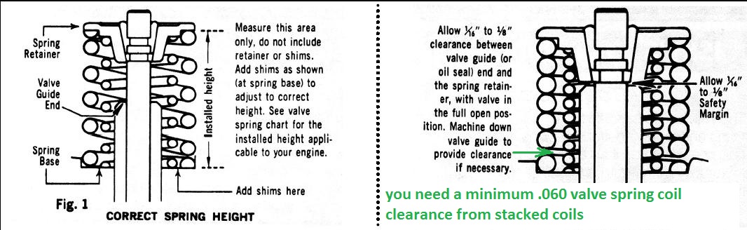
while at first glance at the issue
your obviously 100% correct that spring bind, would be far more critical to engine function.
I think the diagram showing

the extra clearance for the valve seals might be due to the fact,
that,
the diagram shows measuring from retainer to valve seal,
yet the valve keepers in that particular diagram ,
extend below the retainer base
Last edited:
Loves302Chevy
"One test is worth a thousand expert opinions."
Good point and I have seen that for myself. Thanks.
Loves302Chevy
"One test is worth a thousand expert opinions."
I'm ready to break in Version 3.0 of this 334 SBC. Just like the last time, I have 57# oil pressure while
turning the oil pump with a preluber shaft and 1/2" drill motor. One big difference this time - I got a
sufficient supply of oil at ALL of the rocker arms in about 1 minute and without having to
rotate the crank. But just to be safe, I ran the oil pump for another minute while rotating the crank
2 revolutions to make sure the oil gets everywhere it is supposed to be.
So I can already tell that these ISKY lifters are better than those cheap China made P.O.S. "Delphi"
lifters that cost me a camshaft, plus an additional $400 for the new ISKY cam, lifters & springs and
another $100 for shorter TrickFlow pushrods.
And all that time troubleshooting. But I learned a lot, and there CAN'T be ANY problems this time.
Once again, I did everything right. Only the parts themselves can screw me now.
8
87vette81big
Guest
That's not A Luberal Bam Bam Camshaft & Hillary Clitoris set of Lifters you installed Loves 302.
YOU HAVE THE BEST $$$ CAN BUY.
RON ISKENDERIEN MADE 264 MEGA .
CONSERVATIVE AND MADE IN THE USA.
TO THE FICKEN HELL WITH DEMOCRATS & BAM & CHUNA SHIT.
YOU HAVE THE BEST $$$ CAN BUY.
RON ISKENDERIEN MADE 264 MEGA .
CONSERVATIVE AND MADE IN THE USA.
TO THE FICKEN HELL WITH DEMOCRATS & BAM & CHUNA SHIT.
Loves302Chevy
"One test is worth a thousand expert opinions."
I love it. I wish Trump would say that on the campaign trail!Hillary Clitoris
Loves302Chevy
"One test is worth a thousand expert opinions."
I did not fire the engine today because I am trying to have someone take a few videos that I can post
(Rick, I may need your help with this). I will try for Thursday afternoon. Then we can all see my success
.......... or failure.
(Rick, I may need your help with this). I will try for Thursday afternoon. Then we can all see my success
.......... or failure.
I'm here!(Rick, I may need your help with this)
8
87vette81big
Guest
I used my Cheap LG Wally World Smart phone to make Videos and then post to You Tube.
Easy once you get it figured out how to do it.
Easy once you get it figured out how to do it.