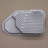
TBucket 200-4R Transmission Project


To install the Valve Body (VB), start with the check balls that go in the worm
casting of the case. Use lube to keep the balls from moving. From the factory
it has 7 balls, but I’m only going to put in the 5 balls according to CKP shift
kit instructions. Even the CKP book calls for 7 check balls, so I had to pay very
close attention to what I was doing and both pieces of documentation. The
book is maybe 6-8 years old now and Chris has made updates to his hard
components and processes.

Also goes in is the 3-4 accumulator piston and spring. The spring is a
CKP replacement.

4355

FP01_3-4Accumulator&Balls_4355.jpg

There are two gaskets and they are different, but you can tell which one
goes where by looking for the letters cut into the gasket. Letter “C” is for
the case and letters “VB” are for the VB side. It’s hard to see, but the “VB”
is pointed out in the photo below.

Put the case gasket on, then the separator plate and then the VB gasket.
Use 4 VB bolts to keep everything aligned while you are installing the
pieces to the 1-2 accumulator.

4363
FP01_Gaskets&SeparatorPlate_4363.jpg

Next goes the accumulator plate and gasket, 1-2 spring (from CKP) and 1-2
housing with piston installed. Torque the 5 bolts to 18 ft/lbs.

4367
FP01_1-2Accumulator&Housing4367.jpg

Next is the VB assembly, but first you need to install the check balls in the
locations shown in the photo below. Again you need to use Vaseline or a
transmission lube. If you are working in summer temps of 80° F and above,
I would recommend the GREEN lube. It’s stable up to 130° F, where Vaseline
is getting pretty thin.

4370
FP01_VB_WithCheckBalls_4370.jpg

You will have to remove the 4 bolts from above first, then put the VB on and
add the other pieces that have to be bolted in place with the VB bolts ….
TV linkage, shifter detent and signal oil pipe.

I haven’t torqued my VB bolts since I still have to figure out my wiring for
the TC lockup system. It's also held in place with the VB bolts.

4376
FP01_ValveBodyInstalled_4376.jpg

All the check balls installed are made from a Viton material according to the
parts counter person at OTS. I think they were about $1.25 each.

4361
FP01_VitonCheckBalls_4361.jpg


Last edited:

Here is his website.
http://ckperformance.com/resources/GM2004RCATALOG.html


Check out the links below....

http://www.rowand.net/Shop/Tech/LockupTCCWiring.htm
http://www.rowand.net/shop/tech/automaticoverdrivetransmissionswap.htm

You will notice in the last link that the TH350 and the TH200-4R are essentially
the same length and output spline. Therefore the driveshaft does not need
modification, only the trans mount is modified. Something to consider if the
700R4 doesn't work out.

The instruction for the CK Performance shift kit PN 24RSRK/A written by
Chris Kokkonis that I have referred to several times thru out this thread
can be downloaded below. 29 Pages


Attachments

  • 200-4R Shift Recalibration Kit 24RSRKA_01.pdf
    814.7 KB · Views: 6
Last edited:
You did it Rick !
" ITS ALIVE ..... ITS ALIVE ....ITS ALIVE EVERYONE .
RICK'S CUSTOM HOMEBUILT 200R4 IS ALIVE !!!! "

:cool:
 
87vette81big said:
You did it Rick !
" ITS ALIVE ..... ITS ALIVE ....ITS ALIVE EVERYONE .
RICK'S CUSTOM HOMEBUILT 200R4 IS ALIVE !!!! "

:cool:
Brian.....Brian.....slow down now!!!
I've never seen you like this. Did the wife put something in your Wheaties??? :lol: :p

DaleEarnhardt.jpg
 
Last edited:
Happy for you Rick.
Building a tough bullet proof auto trans is no easy feat.
At home.
Or by a professional.
 

I wasn't completely sure if I had paid enough attention when disassembling the
governor, but I was able to find someone else that showed the springs and
which weight they go with. So for what ever reason I did have it right.

FP01_GovernorOverview_4392.jpg


Notice that the two springs are different. Light spring goes with the heaver
weight and the heavier spring goes with the lighter weight. Installing the
springs can be real fun. The heavy spring jumped out and took flight, it was
40 minutes later before I found it.......I hate working with springs.

FP01_SpringWeightConfiguration_4398.jpg

The governor is known to have problems with the secondary spring jumping
out during burnouts when the wheels come to a sudden stop. I can see why,
with only small depression on each end of the spring to hold it in place. So I
decided to pull it apart again, then drill and tap the secondary weight for an
aluminum 8-32 screw.

FP01_GovernorModification_04404.jpg

FP01_SpringModification_4399.jpg

During assembly the two balls were held in place with the Trans Assembly Lube.
Once assembled I peened the ends of the pin. The pin can be seen in the first two photos above.

FP01_GovernorShaftDetail_4127.jpg

Install the governor assembly into the case and add the gasket. Don't forget
to replace the seal, seen below on the end of the shaft.

FP01_GovernorInstalled01_4409.jpg

Install the cover and torque bolts to 18 ft/lbs.

FP01_GovernorInstalled02_4411.jpg

 
Last edited:
is there any chance that screw head extending out will cause a problem?
how close are you to being able to bolt the trans, converter and engine up into the t-bucket?
I can,t remember what that t-bucket rear gear ratio and tire diameter is ??
do you intend to actually weigh the t-bucket once its assembled?
did you weigh it the last time you had it running (with you in it) ?
will any local track let you run the car ? I know many tracks will not unless you have an approved welded in roll cage installed , and several other mods done to meet safety regulations.
one reason I ask is I had a neighbor tell me hes seen one of the local guys running a vaguely similar t-bucket up at a local track here in palm beach that weights about 2500 lbs , from what the owner told him, with what he described as a basic 383 sbc engine with a radical solid roller cam and dart platinum 200cc heads and a 750 holley, on a weiand single plane intake and a 4 speed manual transmission, and 4.11:1 rear gears, but that engine as described should have somewhat less potential power that your engine should produce, that cars running very high 10 second quarter mile times, the owner said he had the car chassis dynoed at 405 rwhp, but low 11 seconds is more likely

a quick check with the hp/et calculator shows thats easily possible

http://www.wallaceracing.com/et-hp-mph.php

http://www.race-cars.net/calculators/et_calculator.html
 

Good catch, you might very well be right. I will have to pull the cover off and
take a look. That weight is going to move out more with speed, so I will have
to keep that in mind.

Rear gear ratio is 3.7:1 Ford 9" with positrac or whatever Ford calls it. The tires
are 28" in diameter.

I wasn't planning trying to race it at a drag strip. If I did, I might launch hard,
but I would be getting out of it at half track or sooner. I wouldn't feel safe over
100 mph without a roll cage.

This TBucket in New Zealand did have a problem. He walked away without even
feeling sore later. Too see all the picture use this link.
http://www.tbucketeers.com/threads/i-cr ... ost-158517

Impact3.jpg
Aftermath.jpg

Hot Rod Todd said:
I have a big block chev with a 671 supercharger on it.
Was a great & reliable street & strip motor till I started looking for 9 seconds
on the quarter mile. Now its 540 cubes with the blower & its an expensive, too
heavy drag car. And Im not having much fun. (ordered new heads for it on
the weekend)

 
Last edited:
The 4 link Aurora rod ends failed.
Likely cheap china imatation rod ends.
Real Aurora rod ends won't fail. USED ON 8000 HP Top Fuel Dragsters & Funny cars.
Same. Aurora Rod ends supplied with my CCE Pro Magnum 4- link 4130 CrMo kit.

As long as you don't run 12.99 or quicker no roll bar required at most tracks.
You can run 10's or 9's without a roll bar.
Just be prepared to leave the track fast.
Have someone else grab your time slip.
Can't punish you if your long gone.

Rick is super brave.
Be ok.
 
Hey Rick, Took a break from the Nova! Have you decided on your new oil pan for the tranny?
 
grumpyvette said:
(1) is there any chance that screw head extending out will cause a problem?
(2) how close are you to being able to bolt the trans, converter and engine up into the t-bucket?
(3) do you intend to actually weigh the t-bucket once its assembled?
did you weigh it the last time you had it running (with you in it) ?

(1) The screw head was farther away than I thought from the looks of that
picture showed. As you can see below it's better than I expected, but I still pulled
it out and filled the head off some. After I put it in I passed a .030" wire past it
with ease, so I expect it has about .040" to .050" clearance. Since I can't measure
it with the cover on, it's not a very accurate measurement.

For reference, the head of the screw is about .100" tall.

FP02_ScrewClearance_4416.jpg

But my statement earlier about the weight moving out is incorrect. If you
look at the photo below you can see the arm that presses on the check ball is also
part of the primary weight on the other side, so the weight cannot move out any.
So except for some deflection under operation stresses, the weight will not move
out any farther. It's fluid pressure pushing the ball out that makes the weight
move to the inside.

FP02_GovOperation_4419.jpg

(2) Busterrm had kinda of emergency or he would have been here last
Saturday evening and stayed thru this Wednesday with his engine hoist. Time
permitting we would have installed the engine and trans in the chassis. So it
looks like now it will be a few weeks before he can come. But the trip is
for us to CC his heads, my turn to help him for a change!!! If we have
time then we will install the engine and trans then.

(3) I have never weighed the TBucket, I don't really have a great need
to do so, other than curiosity. Many on the TBucket forum have weighed them
and usually it falls somewhere around 1800 lbs. Many use 3/16" wall, but mine
is only 1/8" wall tubing. Making it even lighter, but I sure wish it was 3/16",
this type of frame construction is terrible for torsional rigidity.

 
Last edited:

I moved all the comments associated with suspension to my other thread called
"TBucket Suspension". I wanted to keep this thread focused on the rebuilding
a 200-4R transmission.

viewtopic.php?f=71&t=9420

Sorry guys if this creates any confusion!


After looking over the TCI kit instructions, I decided that I had everything to
complete their setup, except the vacuum switch, which you can purchase for
about $29. The switch is made by "World Magnetics", see the link below for specs.

http://www.designflexswitches.com/switches/psf101.php
FP01_VacuumSwitchCloseUp_4412.jpg

For the TCI instructions to make sense in my mind, I had to make my own
drawing. I made my drawing from these diagrams in the TCI instructions.

http://news.compperformance.com/Instructions/376600.pdf
FP01_TCI_Drawing01.jpg

FP01_TCI_Drawing02.jpg

The drawing directly below comes from the TCI information, the final drawing
with all changes is posted further down in this post and is called “ElectricalDrawingFinal02“.

ElectricalDrawingDraft01.jpg

The oil pressure switch they use can be purchased at any transmission supply
for about $7 bucks.

FP01_OilPressureSwitch_4384.jpg

Once I got started with the trans in front of me, I noticed that I would have to
cut off one wire and add to another, which didn’t make sense for my situation.
I already had two wires that were the right length in the wiring harness. So to
make my drawing correct, I just moved the wires on my drawing so they went
thru the correct pin for my harness. In another words, I just made the drawing
agree with my wiring harness.In the TCI kit, they supply the internal wiring
harness, so they could set it up any way they want.

ElectricalDrawingFinal02.jpg

First I laid out the harness on the valve body so I could see how it was going
to work physically.

FP01_WiringHarness01_4420.jpg

All I had to do was very simple; just add one wire coming off the negative wire
going to the TCC solenoid and connect it to the pressure switch. I already had
a second harness since I had two transmissions, so I cut off one connector that I
needed. I think the photo pretty much tells the story about splicing it into the harness.

FP01_WiringHarness02_4425.jpg

I noticed that if I put the connectors on pointing at each other, they would go on
far enough to touch each other. So I changed the direction of the white wire as it
approaches the switch. See photos below.

FP01_ConnectorsCouldTouch_4429.jpg
FP01_FinishedWiringHarness_4439.jpg


Theoretically, you don’t have to install the switch, that’s optional if you want to
manually lockup the torque converter in 2nd and 3rd gear.

Download the final electrical drawing below for printing:

https://dl.dropboxusercontent.com/u/790 ... wing02.pdf


Last edited:

Curiosity got to me, I wanted to know at what pressure the switches were
changing state. Thus satisfying one of the parameters for locking up the
torque converter clutch in 4th gear. So I setup this quick test you see below
in the photos. I used the gauge on the painting regulator to measure the
pressure when I saw the DVM change, showing the switch had opened or
closed it's contacts.

Below are my findings, copied directly from my notes.

Measured pressure at which the switch changes state. 4th Gear Pressure Switch
37 psi Normally Closed, 1 Prong, Removed from old transmission.
34 psi Normally Closed, 1 Prong , Removed from old transmission.

22 psi Normally Open, 2 Prong, PN 65618A, $6.73
Fits TH200-4R, TH700-R4, 4L60-E, 1982 – Up
Purchased at Oklahoma Transmission Supply

FP02_OilPressureSwitchTest02_4383.jpg
FP02_OilPressureSwitchTest01_4380.jpg


I also measure the resistance of the TCC solenoid for future reference. I also
came across the same info in the TCI instruction that you see quoted below.
The complete document is referenced above if you want to download it.

Measured the resistance of the CKP lockup solenoid at 21.2 ohms.
Measured the resistance of the old lockup solenoid at 24.4 ohms.

FP02_TCC_Solenoid.jpg


Q: How do I know if my solenoid is good?

A: The first step in determining if your solenoid is serviceable is to
test the electric coil. You will need a simple test meter that can
check resistance. Resistance is measured in Ohms and uses the
following symbol: Ω. This is important to check because some of
the most frequent problems arise from the use of a solenoid that is
electrically shorted out internally. A good solenoid will measure
between 24.5Ω and 26.5Ω. If you get a reading outside this range
then the solenoid should be replaced. If the solenoid checks well,
electrically, it can also be tested for mechanical function. With no
power applied you should be able to blow air through the end of the
solenoid. Then put power to the solenoid (12V to positive side &
ground the negative side) and the coil should force the checkball
onto its seat, preventing air from going through the solenoid. Also
be sure to inspect the condition of the rubber 0-ring on the end of
the solenoid. It needs to provide a good seal inside the bore where
it is housed. Replace if necessary.

 
Last edited:

The new aluminum oil pan came in, so here are a few more details on
it's specifics. Made in USA, cost shipped to my door was $238.90

FP02_PML_OilPan03_4461.jpg
FP02_PML_OilPan02_4460.jpg
FP02_PML_OilPan01_4459.jpg


Last edited:
Magnetic drain plugs have a small permanent magnetic embedded in the end that sticks in the oil.
Usefull for early diagnosis for checking abnormal wear particles.
All iron based metals will stick too.
Should have no more than a light dusting of picked up metal wear.
Like when changing. trans fluid, engine oil, or rear diffetential gear oil.
 

When you look at the filter for a 200-4R trans, it becomes quickly apparent for
performance applications there is a problem with the filter feeding from the top.
So like most people I'm converting to the 700-R4 filter that feeds from the
bottom. But it's not just a simple replacement, it requires a deeper pan and then
some modifications.

FP01_FilterComparison01_4487.jpg

The PML requires modification to work with the 700-R4 filter, since the stands
are too high, but that's why we have grinders to custom fit things for the application.

I'm not sure why, but every post I read they seemed to be worried about the
connectors on the 4th gear pressure switch shorting out on the filter. But both
filters are plastic on the connector side. Since I already had some concerns
about the two connectors touching each other, I decided to insulate them from
each other and the filter.


FP01_FilterInstalled01_4476.jpg
FP01_FilterInstalled02_4478.jpg
FP01_InsulatedConnectors02_4468.jpg
FP01_InsulatedConnectors01_4473.jpg
FP01_InsulatedConnectors03_4474.jpg

First I wanted to see where the stands of the PML pan was touching the
700-R4 filter.

FP01_FilterToPanSupports01_4488.jpg

The stands started out at 3/4", and ended up with the height you see in
the photo below.

FP01_PanFilterSupportHeights_4491.jpg

Since the filter is a different shape, I had to move the wiring supports. The
support you see at position "A" is one I added from the 2nd trans I have.

FP01_WiringSupports01_4481.jpg

 
Last edited:
Back
Top