Thanks....that means alot coming from you Grumpy !!!grumpyvette said:WOW! thats IMPRESSIVE ENGINE WORK
and IMPRESSIVE PHOTOGRAPHY,
CONGRATS ON BOTH!
while Ive done the engine work dozens of times...
your skill at both doing the work and posting the threads info with the CLEAR DETAILS, LOGICAL INSTRUCTIONS AND PICTURES is far beyond average, I,M IN AWE!
You are using an out of date browser. It may not display this or other websites correctly.
You should upgrade or use an alternative browser.
You should upgrade or use an alternative browser.
TBucket Engine Project (Dart SHP)
- Thread starter Indycars
- Start date
Wondering if this is a problem. I left the block and crank covered in a bag for a couple of weeks and it developed
some rust. I used some 2000 grit wet-or-dry sand paper and WD40 to clean the rust from the cylinders. As you can
see from the picture there is still some staining left, like between the arrows and down about 1". I think I can do
better with a little more work with 2000 grit, but will that be a problem for the cylinder roundness.
The deck only needs 0.002" milled to give me 0.040" deck clearance. I was going to leave it at 0.042", but now I'm
wondering if I should go ahead and mill the deck a couple thousandths.


Last edited:
the (RUST) is minimal, youll have ZERO problems, but as I stated previously you should, contact the piston manufacturer, and ring manufacturers, for info on where and how to measure the pistons and what the correct bore clearance, and hone grit should be! as fit and lubrication is critical to durability, get the fit too tight and you can scuff the pistons, the engine tends to run hotter. get the piston to bore side clearance, too loose and the engine burns oil and may be noisy and slightly more prone to detonation if you get oil past the rings, pistons are not exactly round, they expand as they heat up so you must know where to measure clearance
When I bought the Brodix IK200 heads, I got them with the dual valve spring option(CC987) that's good to .575" lift. There should not be a problem with coil bind, since my theoretical valve lift is 0.562/0.567 with the rocker arm ratio of 1.52:1, but we still have to verify.
Since Brodix uses the CompCams valve springs, I went to their website and found their stated "Bind Height" is 1.15".

The rocker arms I'm using are the CompCams Ultra Pro Magnum.

The minimum clearance I measured using Snap Gauges like those shown in the graphic (not my actual heads) was 0.083" on two valves. The
recommended clearance is 0.060" leaving me an additional 0.023". Looking at these numbers, tells me the largest lift cam I could install with this setup is 0.590" (.567 + .023 = .590).

Below is shown all clearances for both heads, along with my calculations for theoretical valve lift of .562 and .567".
The installed height varies by 0.020" or 7.4 lbs seat pressure (370 lbs/in x .020" = 7.4 lbs), is this close enough or should I be adding spring shims to bring all installed heights to 1.8"???
NOTE: For the spring rate 370 lbs/in see valve spring table above.

Now that I got my Crane Teflon valves seal in house, I can check the Retainer to Seal clearance at maximum lift, defined in graphic above called "ValveSpringClearance01.jpg".
Last edited:
grumpyvette said:how far a long are you on each of the component sub- assembly's and basic engine build all together?
pictures?
how long until the engines installed?
The heads are at the machine shop to be milled, then I can assemble them with the light checking springs so I can do my clearance/geometry checks with the camshaft.
The block still needs cam bearings and freeze plugs installed. I'm on the fence about milling the block to cleanup the head surface. I measured .021" deck height, but that's with the piston pushed down in the cylinder. If you subtract the .002" rod bearing clearance I have .019" deck height. I bought the SCE .021" copper gaskets, so my deck clearance now is.038-.040". While I was setup for measuring the deck height, I pushed up on the piston from the bottom to get .019". I would like to take just enough to clean the deck surface, but I would most likely need to buy different head gaskets to get back to a reasonable deck clearance. BTW, the piston to cylinder wall clearance is .0025" to .003".
I still need to check the rotating assembly for clearance around the block and camshaft and then have it balanced after I check the piston to valve clearance.
I'm most likely not going to install the engine this summer. I still need to rebuild the transmission. So I might as well just go ahead and move from TH350 to the TH200-4R and get the OD trans. So next spring will be the earliest that I might drive the car again.
This is what I'm working on this weekend.
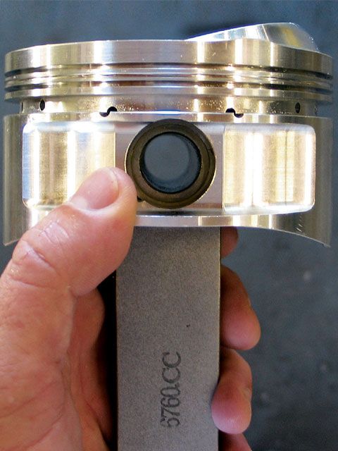
I'm measuring the "Ring Side Clearance". I get less than .0015" on ALL top rings measured in each piston. My understanding is you need .002" - .004" side clearance.


To confirm my measurements I tried a different approach, but less accurate in my opinion.
First I measured ALL the top rings with my ball mike you see in the pics and got between .0582" to .0583" in three places around each ring.....very consistent dimensions for the rings with a delta of only .0001".

Next I used 3 feeler gauges together totaling .059" (.018+.020+.021), which had a nice drag as I pulled them thru the piston ring land. But when I used the ball mike to measure all 3 together I got .060", which I kinda expected.

Therefore...... 0.060" - .0583" = .0017" ring side clearance. I believe the first method to be more accurate, certainly I don't have more that .0015" clearance. Mahle must of intended to have this clearance, since every piston is this way, not just one or two that were out of spec.
What do you think about these Ring Side Clearances ???
I found this very interesting bulletin from Mahle dated July 11, 2011 that stated.... the side clearance is much more important to ring seal than having a small back clearance.
Download the Mahle technical bulletin TB7001 below
Attachments
Last edited:
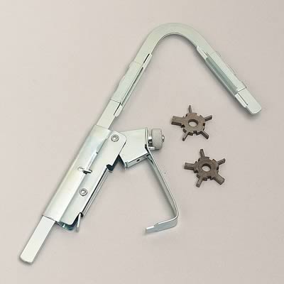
looks likes time to use a ring groove clearance and cleaning tool
http://www.summitracing.com/parts/WMR-W80576/
http://www.summitracing.com/parts/WMR-W80576/
mathd said:Darn, you spending lots of time with this baby :O.
I see you want it more that perfect")
More than perfect.......really that's possible! :shock: I'm going to have to rethink what I'm doing then !
Thanks for the comment!
Do you really think I can cut only .001" and leave a clean & smooth surface for the ring to seal against in the piston ???grumpyvette said:looks likes time to use a ring groove clearance and cleaning tool
http://www.summitracing.com/parts/WMR-W80576/
Indycars said:Do you really think I can cut only .001" and leave a clean & smooth surface for the ring to seal against in the piston ???grumpyvette said:looks likes time to use a ring groove clearance and cleaning tool
http://www.summitracing.com/parts/WMR-W80576/
with the correctly sharp cutter and careful use ,with a good bit of cutting fluid,to keep the mini chips cleaned out of the ring groove, and a depth mic and feeler gauges , yes you can do a decent job and get good results with that tool, it may not be absolutely perfect but, if you work carefully and take your time, it will be far more precise than whats required to have the parts fit and function exactly as designed
btw if you want to almost any machine shop can do the job rather reasonably, but having seen the excellent results you've produced on parts youve produced and modified previously I have zero doubt your hardly challenged here.
if you have a parts cleaner with a running pump spray ,
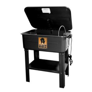
some clean fluid will make the job rather easy,to do by hand, just be sure to clean and dry the parts very carefully when your done,
high pressure air,
a magifying glass ,
good lighting,
a depth mic,
feeler gauges
and some
WD 40 sure won,t hurt
I called Mahle Motor Sports and talked with Brad about the ring side clearance. He said that the ring groove is so flat that it's supposed to only have .001" of clearance. I don't feel comfortable trying to change the side clearance and will leave it where it is. I think Mahle must know what they are doing to design it that way.
This quote from Hotrod.com seems to support that statement, although not directly to the side clearance.
http://www.hotrod.com/techarticles/engi ... ewall.html
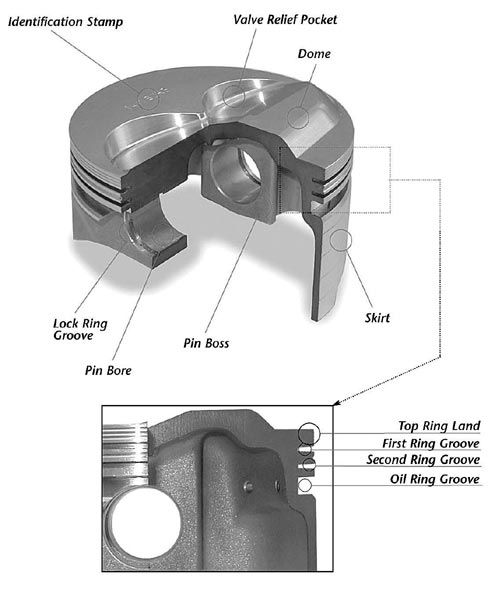
The Piston
To work properly, thin rings must be absolutely flat with no runout. According to Gillis, "Rings seal at the bottom of the piston ring groove as well as the outside perimeter of the ring. As the rings got flatter, we had to make the ring grooves flatter." Only modern, precision CNC-machining can achieve such absolutely flat piston ring grooves. "You don't make pistons on a lathe anymore," Gabrielson says with a chuckle. The plus or minus tolerances have been tightened up to such an extent that some manufacturers now claim to hold tolerances to the millionths of an inch (one microinch or 0.000001).
While I had Brad on the phone I asked about the purpose of the groove in the second ring land. Braid said, " it was a accumulator groove". It accumulates any gases that get by the top ring and apply pressure to the bottom side, which tries to un-seat the top ring.
In the same article in hotrod, they also talked about the accumulator groove. Quoted here:
Another common practice is adding an accumulator groove between the first and second ring to help fight inter-ring gas buildup. This helps reduce pressure between the top and second ring, aiding in top ring seal while minimizing ring flutter. You can use an accumulator groove with conventional ring grooves and undercut second grooves or (even better) with a Napier second ring-they are mutually compatible.


Last edited:
The idea behind the side clearance is to give the gases a path to get behind the ring and push it out, sealing against the cylinder wall during combustion. But like you if Mahle says it should be .001", then I'm not willing to take a chance trying to increasing the clearance. It was built to the design specs, it's not like I caught a mistake in manufacturing by Mahle.mathd said:This measure is probably used when re-using old piston to measure if they are still withing specs?.
And i dont think one can machine the piston at home as accuratly as they are already. If they say they are made to have 0.001" i would NOT touch that.
I appreciate Grumpy's confidence in me to increase that clearance, but I'm just not willing to take a chance.
your most likely not going to have any issues,either way and everything looks good,
( BTW as always your photographic skill is very impressive)
( BTW as always your photographic skill is very impressive)
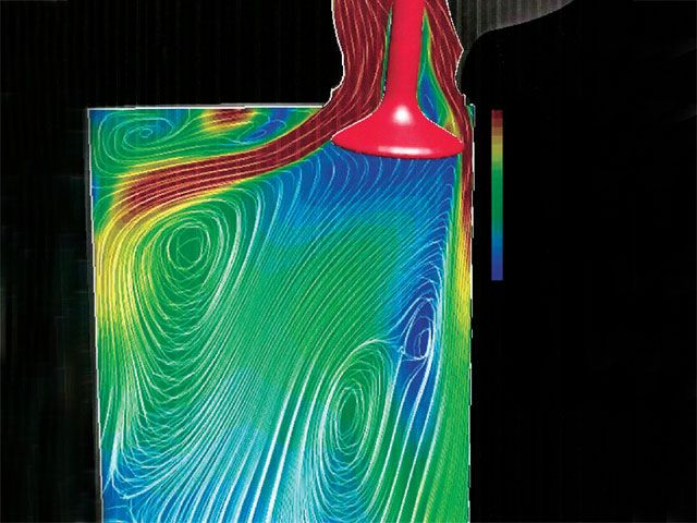
Since there is more to the combustion chamber than just the bowl area, I wanted to see what I could do with the flat surfaces that make-up the the combustion chamber.
I put masking tape on the head where it was needed to scribe a line, defining the cylinder bore. Bolted the head on with 4 bolts, flipped the block over and reached in from the bottom end to scribe the lines for each cylinder.


Then I just peeled away the tape exposing the flat surfaces that make-up the combustion chamber. Next I used a unitized wheel, 600, 1000 and 2000 wet-or-dry sand paper to smooth the surfaces. The masking tape that was left, protected the gasket surface from my polishing.


Finally I used rouge and a felt bob to polish the surfaces. This aluminum just does not get a mirror looking shine on it, like I would like. Maybe it's just my process and not the aluminum at fault here.

I put masking tape on the head where it was needed to scribe a line, defining the cylinder bore. Bolted the head on with 4 bolts, flipped the block over and reached in from the bottom end to scribe the lines for each cylinder.
Then I just peeled away the tape exposing the flat surfaces that make-up the combustion chamber. Next I used a unitized wheel, 600, 1000 and 2000 wet-or-dry sand paper to smooth the surfaces. The masking tape that was left, protected the gasket surface from my polishing.
Finally I used rouge and a felt bob to polish the surfaces. This aluminum just does not get a mirror looking shine on it, like I would like. Maybe it's just my process and not the aluminum at fault here.
Last edited:
polishing the surface of the combustion chamber tends to reduce carbon or ash build up and tends to very slightly reduce the tendency of most heads to get into detonation as quickly, Ive always felt that polishing combustion chambers was a fairly easy and cost effective way to reduce potential problems with detonation at high compression levels and increase power.
Now I'm fairly sure it would take a skilled dyno test to see the difference in power in most cases , but theres no question in my experience that the engines tend to run a bit cleaner and have less ash coating the combustion chambers when you tear the engines down for maintenance refresh builds
viewtopic.php?f=52&t=2630&p=13145#p13145
grumpyvette said:polishing the surface of the combustion chamber tends to reduce carbon or ash build up and tends to very slightly reduce the tendency of most heads to get into detonation as quickly, Ive always felt that polishing combustion chambers was a fairly easy and cost effective way to reduce potential problems with detonation at high compression levels and increase power.
Now I'm fairly sure it would take a skilled dyno test to see the difference in power in most cases , but theres no question in my experience that the engines tend to run a bit cleaner and have less ash coating the combustion chambers when you tear the engines down for maintenance refresh builds
If visual appearance is an indication of well the polishing works to stop buildup and detonation, then I have my doubts how effective the job that I did will work. Since I can NOT sand and polish outside of the cylinder bore line on the head, it makes the job harder. If I could just leave the tape off and polish at will, the job would be a lot easier to get a much better surface.
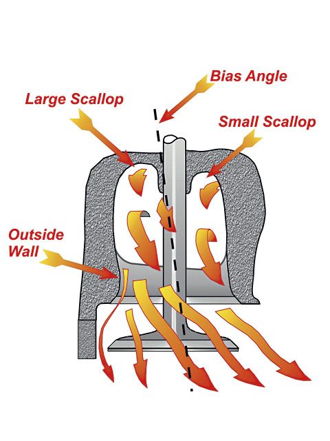
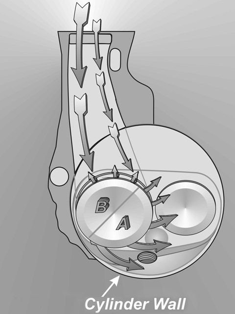
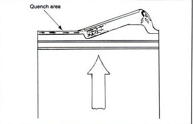
What kind of gains can be expected by opening up the cylinder where the chamber/valve extends outside of the cylinder bore ??? You are limited by the top of the ring travel of course.
NOTE: The drawing is over exaggerated concerning the flow path.

Last edited:
it looks really bad in your diagram , but in reality the curtain area is a small circle tangent to a larger outer circle and the shrouded area extends only a few degrees making it not nearly as restrictive to flow as your diagram might suggest, as airflow simply tends to move from areas of higher restriction to areas of lower restriction, in most cases simply tightening the cam LSA and a slight increase in duration allows exhaust scavenging to assist the draw on the incoming runners mass resulting in more complete cylinder fills, your CROWER 00471 is well matched too and certainly able to provide the power and flow with those heads, especially if youve got anything close to decent headers
since this is a street driven car having fairly long header primaries in the 1 3/4" diam. 36"-38" long range and a fairly long 3" diam/16"-20" collector might be helpful , the picture of that T-bucket suggests your in great shape with those headers

viewtopic.php?f=52&t=2630&p=13142&hilit=curtain#p13142
viewtopic.php?f=52&t=4081&p=10861&hilit=curtain#p10861
I DON,T KNOW about you , but I can,t wait to see this engine run!
after putting all the attention to minor detail into this and knowing the results Ive got in the past from similar builds, Im sure it will be rather impressive in a 2000lb car, its bound to be a real fun car to drive with enough low and mid rpm torque too, allow you to do rather crazy stuff that makes owning the car a real GRIN!!
since this is a street driven car having fairly long header primaries in the 1 3/4" diam. 36"-38" long range and a fairly long 3" diam/16"-20" collector might be helpful , the picture of that T-bucket suggests your in great shape with those headers
viewtopic.php?f=52&t=2630&p=13142&hilit=curtain#p13142
viewtopic.php?f=52&t=4081&p=10861&hilit=curtain#p10861
I DON,T KNOW about you , but I can,t wait to see this engine run!
after putting all the attention to minor detail into this and knowing the results Ive got in the past from similar builds, Im sure it will be rather impressive in a 2000lb car, its bound to be a real fun car to drive with enough low and mid rpm torque too, allow you to do rather crazy stuff that makes owning the car a real GRIN!!
I agree 150% !!!grumpyvette said:after putting all the attention to minor detail into this and knowing the results Ive got in the past from similar builds, Im sure it will be rather impressive in a 2000lb car, its bound to be a real fun car to drive with enough low and mid rpm torque too, allow you to do rather crazy stuff that makes owning the car a real GRIN!!
Thoughts keep creeping into my mind....Bonneville....go to Bonneville. Just pull this motor out of the TBucket once a year and put it in another chassis. Certainly would be a true test of the motor's potential.
I have done my FINAL CC'ing of the combustion chambers after ALL WORK has been done and they were milled .006" on one head and .0095" on the other. I'm very pleased with the outcome, I was shooting for 70 cc.

Last edited:
OUTSTANDING! WORK!, probably not critical, to get things down to a tenth of a cc or less BUT GREAT WORK AND ATTENTION TO DETAIL!
your certainly leaving nothing to go wrong, this should be a really nice combo!
your certainly leaving nothing to go wrong, this should be a really nice combo!