You are using an out of date browser. It may not display this or other websites correctly.
You should upgrade or use an alternative browser.
You should upgrade or use an alternative browser.
TBucket Engine Project (Dart SHP)
- Thread starter Indycars
- Start date

well whats keeping you from completing the project currently?
Well lets see, let me get to my documentation...... viewtopic.php?f=99&t=4894grumpyvette said:well whats keeping you from completing the project currently?

Do a final CC of the heads
Intake gasket match heads
Intake manifold gasket match
Clean and reassemble and check valve seats with alcohol. I may have touched a few during my mods.
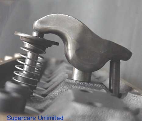
Check spring bind clearance
Check oil pump relief piston for free movement
Check gear for end clearance
Reassemble oil pump
Install cam bearings and freeze plugs
Deck block
Install magnets and screens in valley
Paint block inside and out
Check rod side clearance
Check rod bearing clearance
Verify piston to bore clearance done by machine shop
File fit rings
Degree camshaft
Check piston to valve clearance
Modify distributor for better oiling of distributor gear to cam gear
etc, etc
Last edited:
I'm at a lose to explain the sudden difference in chamber volumes up to 1.7 cc on the drivers side
head . The passenger side chamber volumes did not vary more that 0.2 cc from the last measurement.
As you can see from the screen shot of my Excel spreadsheet I've taken lots of measurements while grinding
the chambers to make their volumes equal.
Can I have the head milled on an angle sloping from front-to-back to making them all equal at about 70cc ???
It would need roughly 0.010" on one end and 0.002" Or does this create other problems along with added costs???
Any ideas why they appear to have changed size so drastically ???
Last edited:
yes you can have the heads angle milled on the deck surface to equalize the chamber volumes, but you do realize your taking a chance the machine shop will further screw the heads up?
this is easily done by an experienced and skilled head surface mill operator, but.
making such a small angle cut correctly takes time to set up and its easily screwed up if the machine shop has no good idea what they are trying to accomplish or doesn,t have the experience, skill or machinery to do it correctly
lets assume the machine shop guys a moron and angle mills the wrong end of the head surface, to much and angle mills it on two angles ....now what
ID have a long talk, with the head machinist first, and make damn sure they understand exactly whats needed and how its to be done
read this
viewtopic.php?f=50&t=2988&p=9055&hilit=angle+mill#p9055
I'm still trying to understand why such a drastic change. The only thing that I've thought of so far is using the same valves for many of the checks. Then I get to the final check after grinding to size and polishing and I pick a different set of valves. I thought about this prior to doing this, but did NOT think there could be much difference in valves when they are all NEW in a new set of heads.
Maybe I need to CC all chambers again with their original valves ??? Just like it will be after final assembly.
Indycars said:
Maybe I need to CC all chambers again with their original valves ??? Just like it will be after final assembly.
sounds like a plan to me!
I put the correct valves in for the chambers 1 & 3 and CC'ed again, didn't make any significant difference. Starting
to grasp at straws now, so I put the head and valves inside over night where it's 74F, in the garage it's usually about 98F.
The next day I moved the rest of my equipment inside to the kitchen and did my measurements there. I'm still 1.8 and 1.9 CCs
larger just from polishing after I ground the chamber walls to equalize their sizes. I was having a hard time grinding enough to
increase the chamber 0.5cc, that seemed like a lot.
Looking at the graphic below you can see I measure #1 eight times before having the problem. How could I make a mistake
eight times and then start getting it right. (Shaking head in dis-belief !!!)
Ok, I know it must have something to do with the phases of the moon !!! Hopefully someones else has an
idea, because I would be willing to entertain any ideas as to why their sizes changed so drastically.
I need another BRICK WALL for my head, this is driving me crazy !!!
Last edited:
your probably not biting the tip of your lip correctly while tipping your head at the correct angle and squinting at the heads.

:lol:
don,t get crazy, just do the best you can, and realize that 99.9" of the engines running around have had a good deal less care taken in their construction than youve already done, I,M not saying it won,t effect results, but the difference is MINIMAL
:lol:
don,t get crazy, just do the best you can, and realize that 99.9" of the engines running around have had a good deal less care taken in their construction than youve already done, I,M not saying it won,t effect results, but the difference is MINIMAL
Ok, I have some thoughts concerning the big difference in chamber volumes suddenly, I will try to comment on this later.
At this point I'm trying to decide if I need to go back and open up the head with the smaller chambers OR can I just mill about 0.010" off the head with the larger chamber volumes. With all the work and sliding the head around on the bench in grit from cartridge rolls and unitized wheels, I now have surface scratches on both heads.
If the head with the small volumes does NOT need to be cleaned up with milling cut, then I can just mill the head with the larger chamber volumes and bring it back to about 70 CCs and be done. If not then I need to open up the head with small chambers, so I can also take a cut on it's surface.
So the question is..... just how perfect does the block to head surface have to be ??? Does the head with small chambers meet this requirement ??? The scratch shown in the second pic is large enough to catch my finger nail in. I know the finger nail is a very sensitive measuring instrument, so any thoughts.
The head gasket is a SCE copper 0.021" thick gasket. , #011152.
http://www.summitracing.com/parts/SCE-011152/


Last edited:
I can,t tell from the pictures, but if it was my head Id suggest taking it to a local machine shop and having them look at both heads and mill off whats required on one or both , after he makes a close detailed inspection, minor scratches tend to get filled with the COPPER-COAT spray when the heads are installed with the copper gaskets, but ,because I can,t see the true depth Id strongly suggest having a MACHINE SHOP that does head work at least inspect them and most likely take a minimal cut on the larger chamber size head to make it match the smaller
Indycars said:Thanks!!! Just wanted to make sure I wasn't being overly picky again.
So you don't think my finger nail is a good substitute for a Profilometer.
not really.....thats about like asking if a good ruler is as precise as a dial caliper
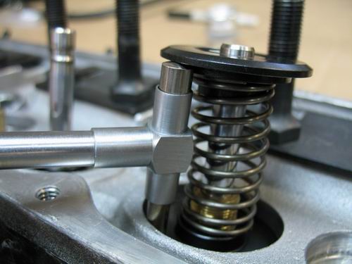
With the valve face horizontal I poured Alcohol in the intake port. After 60 seconds, I turned the head
up so the valve face was now vertical, like in the picture. When I did this there was enough alcohol
around the valve that it collected and ran out. I'm using CompCams checking springs.
Should I see absolutely nothing after 60 seconds or does this look acceptable ???
I've tested four valves and they all have similar leaks.
Last edited:
thats most likely acceptable,most check springs have very low seat pressure
Wanted to see for future reference, just how much difference the CompCams 987 dual valve spring would
make over the CHECKING springs. So I assembled the very same intake valve using the CC987 spring.
After 10 minutes with Alcohol in the port, there was ZERO LEAKAGE !
Which spring do you use when checking the condition of the valve seats ???

make over the CHECKING springs. So I assembled the very same intake valve using the CC987 spring.
After 10 minutes with Alcohol in the port, there was ZERO LEAKAGE !
Which spring do you use when checking the condition of the valve seats ???
Last edited:
Indycars said:Wanted to see for future reference, just how much difference the CompCams 987 dual valve spring would
make over the CHECKING springs. So I assembled the very same intake valve using the CC987 spring.
After 10 minutes with Alcohol in the port, there was ZERO LEAKAGE !
Which spring do you use when checking the condition of the valve seats ???
Ive got a set of check springs that I picked up at a local hardware store 40-45 years ago, they are 2.25" tall and 1.125" in diam and have about 20 lbs of pressure fully compressed
they look very similar to these, the really large hard ware stores usually have an assortment
summit sells some similar but smaller springs
http://www.summitracing.com/parts/PRO-66793/
http://www.jegs.com/i/Proform/778/66793/10002/-1
RELATED INFO
viewtopic.php?f=52&t=1748&p=4398&hilit=lapping#p4398
viewtopic.php?f=52&t=3143&p=8387&hilit=seats+valves#p8387
viewtopic.php?f=52&t=181&p=7360&hilit=seats+valves#p7360
viewtopic.php?f=52&t=1636&p=3941&hilit=seats+valves#p3941
viewtopic.php?f=52&t=1005&p=1818&hilit=seats+valves#p1818
viewtopic.php?f=52&t=2630&p=13145&hilit=+valve+back+cutting#p13145
viewtopic.php?f=52&t=2787&p=7220&hilit=+valve+back+cutting#p7220
viewtopic.php?f=52&t=1159&p=2362&hilit=lapping#p2362
While checking the seat conditions, it was also a good time to look at the seat width. I tried Dykem like was
suggested in a book I have, but that didn't work for me. A SHARPIE worked nicely. I started out putting Sharpie
on both the seat and the valve, but later I only put it on the valve seat. This seemed to work nearly as well.


The accuracy is questionable when comparing the shinny area to your calipers, I feel actual seat could be different
by nearly 0.005 - 0.008". The exhausts still did not measure to be anywhere near the ideal of 0.080". Being that the
car will see at most 5,000 miles a year, then I think I will leave this as is.
Upon inspection of the seat after the Sharpie and lapping tool, I did notice some possible problems like in this pic
you can see the inconsistent seat width, chamber 3 had similar markings and a noticeable increase in leakage. I
ordered some 800 grit lapping compound to see if this will fix the problem.

Last edited:
You may have read earlier in this thread where there appeared to be a sudden increase in combustion chamber
volume during my work to equalize their sizes and polishing. This may have come about because of my limited
experience. The amount of material (volume) for distance “A†and “B†are very much different, even though the
distance is the same. The volume removed in area “A†would be somewhat less since there is a lot of open space
between the peaks when compared to the solid area “Bâ€. Another contributing factor was the removal of material
from about 100% of the chamber surface when polishing as opposed to just 50% when trying to equalize their sizes.
This is the best theory I can come up with, as to why the surprise on my part.
Last edited:
I got the 800 grit lapping compound and tried to fix the exhaust on chamber #1, but it still looks to me like I have a significant problem with durability.
Agree or disagree ???.......Maybe 400 grit first then 800 grit or am I going to leave a groove in the valve???

Agree or disagree ???.......Maybe 400 grit first then 800 grit or am I going to leave a groove in the valve???
Last edited: