You are using an out of date browser. It may not display this or other websites correctly.
You should upgrade or use an alternative browser.
You should upgrade or use an alternative browser.
TBucket Engine Project (Dart SHP)
- Thread starter Indycars
- Start date
mathd
solid fixture here in the forum
Can't wait to see the result from this engine ") .
.
Wish i was going so far with my engine project, but my lack of knowledges keep me from doing so because i always fear for something to go extremly wrong. I still got alot to learn and this topic is really instructive to me.
.Wish i was going so far with my engine project, but my lack of knowledges keep me from doing so because i always fear for something to go extremly wrong. I still got alot to learn and this topic is really instructive to me.
mathd said:Can't wait to see the result from this engine
Wish i was going so far with my engine project, but my lack of knowledge keep me from doing so because i always fear for something to go extremely wrong.
It's been 15 years since I've built any engine, so I know the feeling you describe.
I still got alot to learn and this topic is really instructive to me.
Glad you find it helpful, I like sharing my experiences as I go thru the process !
I'm wondering about which operation I should do first. Should I :
1 - install screens and magnets
2 - paint the inside of the block
3 - install cam bearings
OR
3 - install cam bearings
1 - install screens and magnets
2 - paint the inside of the block
My original plans was to install cam bearings first, as you can see from my Excel spreadsheet. Hope the text is big enough to be readable.
Once I get the cam bearings installed, then comes some fun stuff......degreeing the cam and checking valve train geometry !!!
The spreadsheet below is available for downloading in "Spread Sheets and Engine Related Forms" section.
viewtopic.php?f=99&t=4894

1 - install screens and magnets
2 - paint the inside of the block
3 - install cam bearings
OR
3 - install cam bearings
1 - install screens and magnets
2 - paint the inside of the block
My original plans was to install cam bearings first, as you can see from my Excel spreadsheet. Hope the text is big enough to be readable.
Once I get the cam bearings installed, then comes some fun stuff......degreeing the cam and checking valve train geometry !!!
The spreadsheet below is available for downloading in "Spread Sheets and Engine Related Forms" section.
viewtopic.php?f=99&t=4894
Last edited:
mathd
solid fixture here in the forum
You do paint the inside of the block?, i know am kind of a beginner on this world, but i would never paint the inside of a block.
I dont want paint chip to fall into the oil or between the piston/cylinder :/. Maby there is a reason that i ignore for painting the inside of the block beside appearance.
Now, if it was me, i do the cam bearing first, because i never did this(for me that mean trying a brand new tool hehe) and its one more step toward cam degreeing wich i also love to do.
Or, depending on the engine progress, i probably do the screen first so i can be done with the oil pan(closed/sealed).
mathd said:You do paint the inside of the block?, i know am kind of a beginner on this world, but i would never paint the inside of a block.
The block is made from a sand casting, hence the texture you see inside and out. That also means there is some sand particles trapped that can come loose and enter the oil supply...not good on the bearing etc.
http://www.eugenesargent.com/casting.htm
I don't want paint chip to fall into the oil or between the piston/cylinder :/. Maybe there is a reason that i ignore for painting the inside of the block beside appearance.
If you prepare the block surface properly and use the correct paint, the paint will adhere just fine.
Now, if it was me, i do the cam bearing first, because i never did this(for me that mean trying a brand new tool hehe) and its one more step toward cam degreeing which i also love to do.
I don't have the tools for installing cam bearings, so I would be taking it to the machine shop
Or, depending on the engine progress, i probably do the screen first so i can be done with the oil pan(closed/sealed).
The screens I'm talking about go in the valley to stop any large pieces from the valve train that break, getting to the rotating assembly/bottom end.
if you use the correct type of paint on a totally degreased block the paint traps and holds micro debris
I usually
(1)clean all threaded holes with taps
(2)send block out to be cleaned or I spray clean with high pressure water and high pressure air and solvents
(3) install shrapnel screens & magnets with epoxy
(4) paint block VERY CAREFULLY, after masking off machined surfaces and using rubber corks on lifter bores
(5) install cam bearings
(6)install freeze plugs
read
viewtopic.php?f=51&t=125
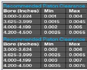
I'm trying to verify the piston-to-cylinder wall clearance that the machine shop set for me. This is what I gave them on paper per Mahle:
Set piston to cylinder clearance at low side of 0.0025" to 0.0033" at 1/2 inch*
* 1/2 inch = The location to measure piston-to-wall clearance, referenced from the bottom of the piston skirt. "Min" and "Max" is the suggested range of clearance over the coating for each application. Mahle recommended clearance = 0.0025 to 0.0033
I don't have a bore gauge to do this properly, but my goal is to make sure there is NO BIG mistakes. I started with a .002" feeler, while holding the feeler in the cylinder I would push the piston past the feeler. Then I moved to the .0025" feeler. The .0025 is pretty tight, but I can still push the piston past a .003" feeler. All cylinders have similar feel/drag when checking all 8 cylinders. If there is a mistake, then it would have to be on all 8 cylinders, since they all have the same clearance checking with the feeler gauges.
Looks reasonable and should work nicely in my humble opinion. What say you???
Last edited:
I think youll be fine!
if your measuring where the manufacturer suggests and your very close to the suggested clearance that way,
remember the aluminum piston expands a bit more with heat than the iron block so once the engine oil temps reach about 200F that clearance between the piston skirt and bore wall will be much closer to just being a few molecules of hot oil film thick
grumpyvette said:I think youll be fine!
if your measuring where the manufacturer suggests and your very close to the suggested clearance that way,
remember the aluminum piston expands a bit more with heat than the iron block so once the engine oil temps reach about 200F that clearance between the piston skirt and bore wall will be much closer to just being a few molecules of hot oil film thick
If you were to measure with a micrometer and bore gauge, then you would have to know where on the piston manufacture wanted clearances measured. But when I put the feeler gauge in the bore, then slide the piston past the feeler, this would automatically measure the minimum clearance. At least it does in my mind.
youve done far more detail work than most guys, I doubt that youll have the slightest problem, I see guys slap together components right out of the box without measuring much of anything and surprisingly even going that route seems to work at least 10%-20% of the time so, knowing how much care youve taken I don,t think at this stage thats a valid issue to worry about.
obviously it depends on bore and piston design, materials etc, but even side clearance as high as .005 Ive seen work, on engines with similar bore sizes
related info
viewtopic.php?f=53&t=4630
viewtopic.php?f=53&t=1795
viewtopic.php?f=53&t=4516&p=16279&hilit=4032#p16279
viewtopic.php?f=53&t=247
viewtopic.php?f=53&t=852
viewtopic.php?f=53&t=5454
viewtopic.php?f=53&t=509
viewtopic.php?f=53&t=2837
viewtopic.php?f=53&t=3897
viewtopic.php?f=53&t=110
grumpyvette said:youve done far more detail work than most guys, I doubt that youll have the slightest problem, I see guys slap together components right out of the box without measuring much of anything and surprisingly even going that route seems to work at least 10%-20% of the time so, knowing how much care youve taken I don,t think at this stage thats a valid issue to worry about.
obviously it depends on bore and piston design, materials etc, but even side clearance as high as .005 Ive seen work, on engines with similar bore sizes
When I read your comments, it looks to me like you are thinking that I'm looking at this like the clearance is too high, which would not be true. With the aluminum 4032 alloy FORGED piston Mahle uses I was hoping to have .0028 - .0030 clearance, which should help with the quench distance, and giving me a little more confidence that there will NOT be any piston the cylinder head contact. Less piston rock at TDC will help in this situation.
Forgive me if I understood your comments wrong.
first keep in mind pistons are a bit barrel shaped vertically (or looking from the side) and oval ,looking down from the top, as the top expands more as it get hotter, and they don,t expand equally as they heat up, your more than likely well within the acceptable range,obviously you can call the manufacturer and get their feed back if your concerned and just as obviously you could hone the bore a bit larger for more clearance, but given what your saying IE your using a feeler gauge and getting about .003 side clearance, (which is more than likely a tiny bit larger because of the way your measuring and the tool used) I think your withing the acceptable range.
but I would call the manufacturer if your concerned, if it was my engine I would have already done that and asked a dozen questions., but after talking with dozens of tech guys Id bet money that you could ask 20 different tech desk guys and get similar but never the same answers talking any of them on any given day,even if you call back and talk to the same guys on different days and probably not the same answer from the same guy twice.
Piston-to-Wall Clearance
The right clearance between the piston skirts and the cylinder walls is absolutely essential. If the
piston-to-wall clearance is too large, the pistons rock back and forth in the bore. This prevents the
rings from sealing the cylinder properly, and can crack the skirts as the piston slaps from side to
side. If the clearance is too small, the piston will literally stick in the bore, scuffing the skirts and
destroying the wall finish. There’s a thin line between too much and not enough, but providing the
correct running clearance pays dividends in both durability and horsepower.

Piston skirts are slightly elliptical when
measured at room temperature. This oval
shape is the piston’s “cam grind.â€

A “barrel face†piston has a skirt that
bulges outward in the center. Because
of this complex shape, it is essential to
follow the piston manufacturer’s
instructions when setting the piston-to-
wall clearance.
but I would call the manufacturer if your concerned, if it was my engine I would have already done that and asked a dozen questions., but after talking with dozens of tech guys Id bet money that you could ask 20 different tech desk guys and get similar but never the same answers talking any of them on any given day,even if you call back and talk to the same guys on different days and probably not the same answer from the same guy twice.
Piston-to-Wall Clearance
The right clearance between the piston skirts and the cylinder walls is absolutely essential. If the
piston-to-wall clearance is too large, the pistons rock back and forth in the bore. This prevents the
rings from sealing the cylinder properly, and can crack the skirts as the piston slaps from side to
side. If the clearance is too small, the piston will literally stick in the bore, scuffing the skirts and
destroying the wall finish. There’s a thin line between too much and not enough, but providing the
correct running clearance pays dividends in both durability and horsepower.
Piston skirts are slightly elliptical when
measured at room temperature. This oval
shape is the piston’s “cam grind.â€
A “barrel face†piston has a skirt that
bulges outward in the center. Because
of this complex shape, it is essential to
follow the piston manufacturer’s
instructions when setting the piston-to-
wall clearance.
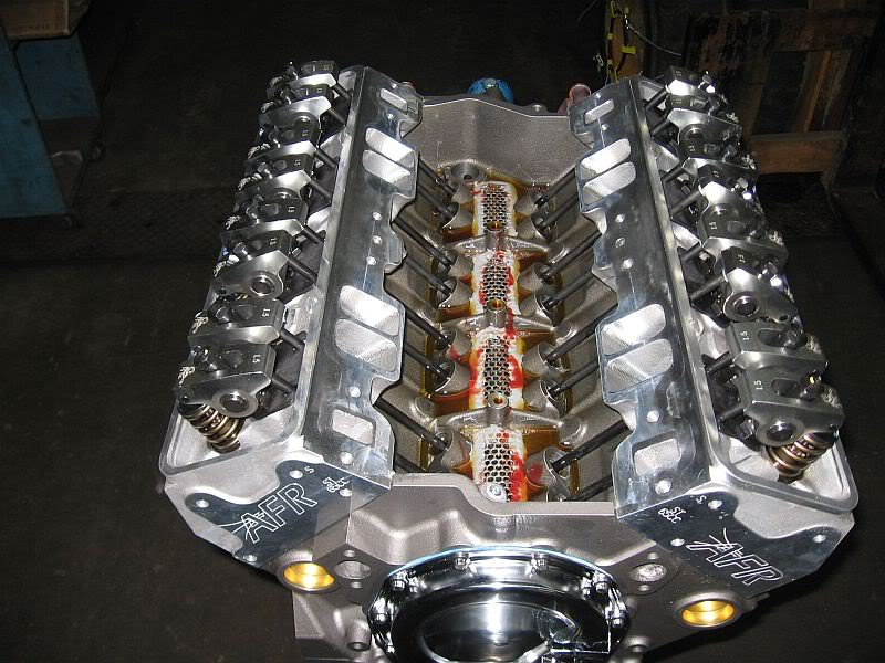
Before I paint the inside of the block, I needed to get the magnets and shrapnel screens installed. Went to Lowes and bought some aluminum expanded metal, that stuff is not cheap, $26 for a 24x36 inch sheet. I have enough to do 15-20 motors now, just need to find a way to get the money.
First thing was to degrease the areas where the screens and magnets were going to be placed. Cut out pieces of metal that were approximately the right size, only the two middle slots were the same size. Then I used a ball peen hammer to form the metal to fit the block. Being that it's aluminum, it was easy to bend with my hands when needed.


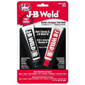
I found it much easier to apply the JB Weld to the screen first, then place into position.

I'm glad that I used the slow setting JB Weld, I didn't have to worry about it setting up before I was finished. I suspect the slower JB is also stronger.

Used a cheap screw driver to add JB Weld after the screen were in place.

Looking at the heads, I confirmed where the most oil would be draining back on it's way to the pan. This is where I placed the magnets. I have 4 more magnets for the oil pan. These magnets came from K&J Magnetics and can with stand temperatures of 300 F. Like these
http://www.kjmagnetics.com/proddetail.asp?prod=D82SH

The next day I rolled the block over and checked for any excessive drips, there were a few. Since the block in these areas still had plenty of oil the drips were easy to remove.

Not picture perfect, but functionally they should work just fine.

Wish the rain would stop so I could do some painting today.
Last edited:
the shrapnel screens and epoxy magnets look just fine, but IM a bit concerned that that perforated sheet aluminum's a bit restrictive to oil flow return rates, Ive almost always used a stainless 6 or 8 mesh screen, as a shrapnel screen, just be careful when you paint, so as not to clog any drain holes, ID also suggest pouring some oil on those screens and see what you think about how fast it drains back, Im glad to see your making progress, guys frequently ask if the screens restrict oil flow and as long as the screens are kept free from sludge, and have numerous and adequately large holes they work great and won,t restrict oil flow, but naturally if you go long stretches between oil changes sludge can AND WILL build up clogging the screens so its not a mod designed for guys who are lax on maintaining constantly clean oil in their engine
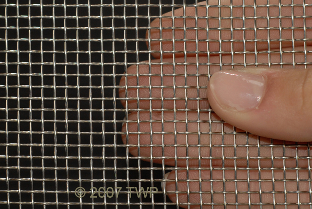
while I generally use stainless 6 or 8 mesh screens theres lots of options that perforated sheet aluminum should work just fine, if the holes are l;arge enough ,just remember to keep the oil changed regularly or theres some potential for sludge to clog ANY size shrapnel screens
http://www.twpinc.com/twpinc/products/T ... 6T0350W36T
http://www.twpinc.com/twpinc/products/T ... 8S0280W36T
IVE typically used these magnets in an engine, one in the rear oil drain on each cylinder head, one near each lifter gallery drain and 4 in the oil pan sump
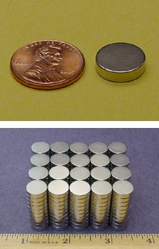
http://www.kjmagnetics.com/proddetail.asp?prod=D82SH
while I generally use stainless 6 or 8 mesh screens theres lots of options that perforated sheet aluminum should work just fine, if the holes are l;arge enough ,just remember to keep the oil changed regularly or theres some potential for sludge to clog ANY size shrapnel screens
http://www.twpinc.com/twpinc/products/T ... 6T0350W36T
http://www.twpinc.com/twpinc/products/T ... 8S0280W36T
IVE typically used these magnets in an engine, one in the rear oil drain on each cylinder head, one near each lifter gallery drain and 4 in the oil pan sump
http://www.kjmagnetics.com/proddetail.asp?prod=D82SH
grumpyvette said:Im glad to see your making progress, guys frequently ask if the screens restrict oil flow and as long as the screens are kept free from sludge they work great and won,t restrict oil flow,
I did waffle back and forth between the screen that I bought and another with larger openings. I just had to say to myself.....self don't over think this !!! So 15 minutes of staring at the two screens and I had made my decision.
I thought about SS, but the aluminum was very easy to trim and mold to the shape I wanted.
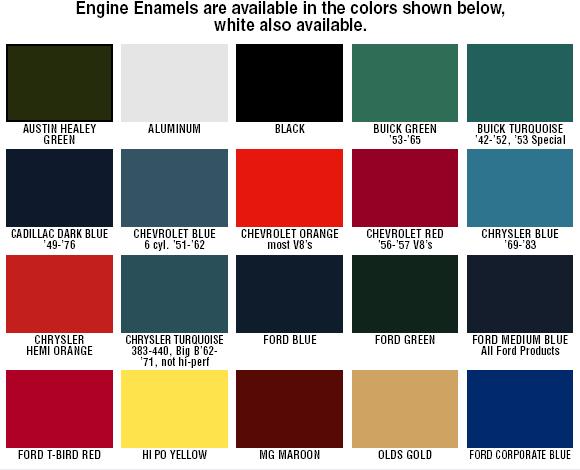
I needed to paint the interior surfaces of the block. I used Por15 Engine Enamel without any primer.
First was cleaning the cam tunnel. I started with spraying the cam tunnel with Brake Cleaner, then I went back with a glove and sock, scrubbed the tunnel and then finish with the spray again to rinse. Next I used Por15 "Prep & Ready" on all surfaces prior to painting. The instructions called for a water rinse, but I went with a careful sparing application and letting it dry completely before painting.
NOTE: Be careful NOT to let any of the Por15 "Prep & Ready" run on to the cylinder bore surfaces.
To reach some surfaces I had to bend the brush at 45 degrees so I could reach around corners. When possible I preferred the foam brush, it didn't leave any bristles in the paint. The tunnel was by far the hardest surface to paint.
All surface required two coats to cover completely. Not sure I would use aluminum color next time. It was bad about separating and leaving streaks of color in the paint.


Last edited:
wow! :mrgreen:
I'm impressed, your doing really nice work!
(both on the engine and behind the camera! )
I finally see someone else thats taking the time to do it correctly,
99% of the guys paint the outer engine, about 30% paint the lifter gallery,
but darn few guys paint the lower crank case, and take the time to do the detail work.
in 40 plus years, that Ive built engines, your the only other person Ive ever seen besides myself that takes the time to plug the lifter bores and paint the blocks cast and UN- machined surfaces to lock in micro crud, in the metals pores, to trap micro debris and help speed oil flow.
I bet 99% 0f the guys don't even own a set of lifter bore size rubber plugs
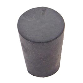
BTW I bought 16 rubber corks to push into the lifter bores to prevent paint entering the lifter bores during the painting, I placed 16 mini-screw eyes in the corks and strung them on a bead chain to keep from loosing them while in storage or in use!
home depot sells those rubber corks and screw eyes, obviously you want the ones that have a small end diam. of about 11/17 and a big end diam, of about 7/8", youll need 16 and 16 mini-screw eyes, and about 3 feet of bead chain
http://www.hometrainingtools.com/rubber ... E-STOP01C/
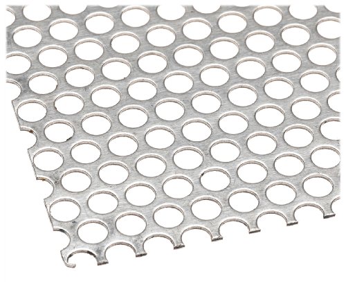
the only thing Id do differently is I,d use either the course stainless 6 mesh screen or a perforated sheet pictured above with larger holes and J&B weld epoxy and magnets , but those are minor tweaks,and theres no real advantage over perforated sheet, and your use of the aluminum perforated plate makes the job easier to do, and most likely easier to epoxy
related threads
viewtopic.php?f=51&t=125
viewtopic.php?f=51&t=2919
viewtopic.php?f=51&t=4692
viewtopic.php?f=51&t=1458
viewtopic.php?f=51&t=281
viewtopic.php?f=54&t=2187
viewtopic.php?f=54&t=120&p=867&hilit=magnets#p867
I'm impressed, your doing really nice work!
(both on the engine and behind the camera! )
I finally see someone else thats taking the time to do it correctly,
99% of the guys paint the outer engine, about 30% paint the lifter gallery,
but darn few guys paint the lower crank case, and take the time to do the detail work.
in 40 plus years, that Ive built engines, your the only other person Ive ever seen besides myself that takes the time to plug the lifter bores and paint the blocks cast and UN- machined surfaces to lock in micro crud, in the metals pores, to trap micro debris and help speed oil flow.
I bet 99% 0f the guys don't even own a set of lifter bore size rubber plugs
BTW I bought 16 rubber corks to push into the lifter bores to prevent paint entering the lifter bores during the painting, I placed 16 mini-screw eyes in the corks and strung them on a bead chain to keep from loosing them while in storage or in use!
home depot sells those rubber corks and screw eyes, obviously you want the ones that have a small end diam. of about 11/17 and a big end diam, of about 7/8", youll need 16 and 16 mini-screw eyes, and about 3 feet of bead chain
http://www.hometrainingtools.com/rubber ... E-STOP01C/
the only thing Id do differently is I,d use either the course stainless 6 mesh screen or a perforated sheet pictured above with larger holes and J&B weld epoxy and magnets , but those are minor tweaks,and theres no real advantage over perforated sheet, and your use of the aluminum perforated plate makes the job easier to do, and most likely easier to epoxy
related threads
viewtopic.php?f=51&t=125
viewtopic.php?f=51&t=2919
viewtopic.php?f=51&t=4692
viewtopic.php?f=51&t=1458
viewtopic.php?f=51&t=281
viewtopic.php?f=54&t=2187
viewtopic.php?f=54&t=120&p=867&hilit=magnets#p867
I'm thinking the screens are a bit too restrictive, which is the problem you are having with them I think.grumpyvette said:the only thing Id do differently is use the course stainless screen and J&B weld epoxy and magnets , but those are minor tweaks, and your use of the aluminum perforated plate makes the job easier to do, and most likely easier to epoxy
I'm thinking about making a couple of slots in each screen by opening up between two holes. Like I show between the arrows below.

Last edited: