TBucket Engine Project (Dart SHP)


I almost finished setting the end gaps Sunday, I will need to go back to the 2nd ring on cylinder #1 and bring it up to .024". It's obvious I lost my focus when it came to the second ring on cylinder #4 at 0.031", not sure what I was thinking about when I was turning the grinder for that ring. After I had gone over .022" for the 2nd ring on cylinder #2, I decided to go with Grumpy's recommendation of .024" for the 2nd ring. I originally wanted .021" on the 1st ring, but if the ends ever touch, then that would be far worse then adding another .001". I thought at .021" I was being conservative, but since Grumpy suggested .022" I revised my number to agree.

My goal was to set the rings as follows:

1st Ring = 0.022"
2nd Ring = 0.024"
Oil Ring = 0.018

This is what I actually ended up with.
EndGapSettingsTable.JPG

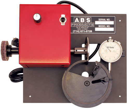
I took the stone off a small knife sharpener to use for deburring the edges of the ring gap.
DeburringStone1433.jpg

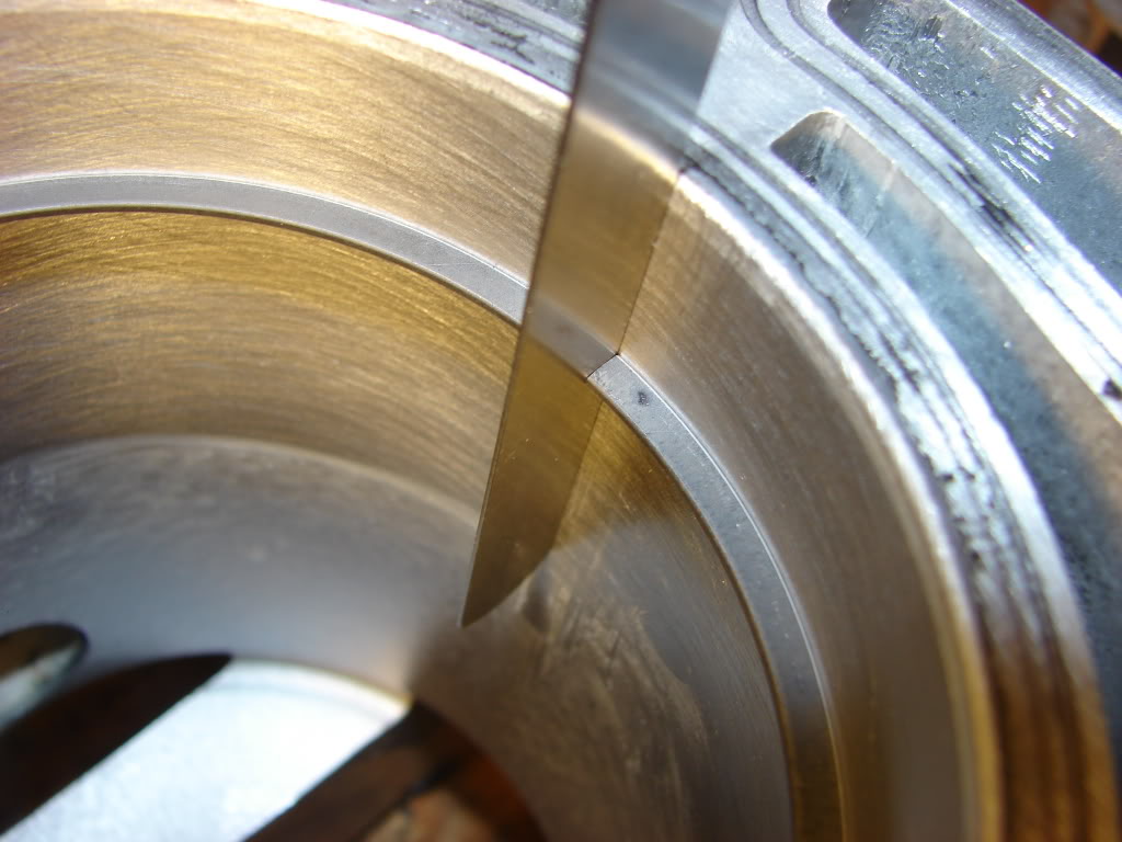
You can see what the trailing edge looks like after grinding in the photo below. I couldn't see these burrs with the naked eye, but I could feel them with my finger nail. Only with 4x magnification could I begin to see these burrs. The 8x magnification in the photo below really bring them to life.
GrindingBurrs1429.jpg


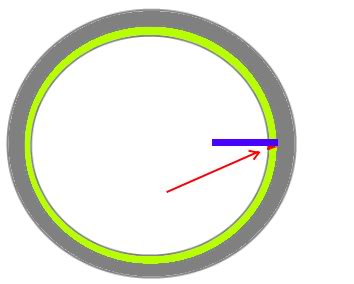
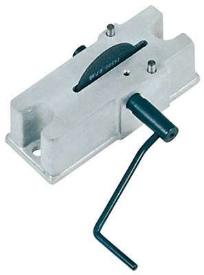
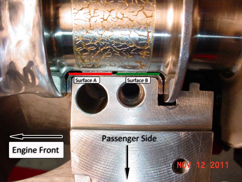
I kept noticing that the gap was slightly bigger at "A", than it was at B"", maybe .0005-.0008" difference. I could get a feeler gauge started, but then it would tighten up about 1/2 down. It finally dawned on me that when they made the ring filer, they placed the grinding wheel centered between the stop pins. The surface where the grinding wheel and ring come together should have been on the centerline between the stop pins.
EndGapNotParallel1313.jpg


So to compensate, when I got to the last 4-5 thousands, then I would shift the ring like you see in the photo below. This gave a much more consistent drag on the feeler gauge all the way thru the ring gap. I only filed one end of each ring gap, labeled "Y".
RingFilerCorrection1420.jpg

 
Last edited:
THATS A GREAT TIP, and as usual, amazing photography,

INDYCARS I look at your excellent photography and Im starting to think my memories shot, I forget to mention things, that are easily over looked, but its the little things you point out that make reading this thread so useful, and well worth the time and effort, because we both are pointing out those factors most guys never think about and your camera skill is truly amazing
damn why can,t I remember to point out those little tricks,I noticed the same thing many years ago, your picture does a great job, pointing out the need to space the ring out a bit to keep the ring end being filed square , a bit of copper tubing about 1/4" long IF I remember correctly its 5/16" thin wall copper plumbing tubing, that just fits over the 1/4" post and remembering to only file the far end of the ring keeps the ring end gap angle geometry much closer, the tiny bushing is kept in place with a tiny o-ring epoxied to the upper post end


If you're grinding the entire face, but not square, when you check your end gap as you should be doing frequently, you will see that the feeler gauge will slip easily into the inner edge but won't move all the way to the outer edge/bore wall. The error looks like:
RingsmallMessup.jpg


If you're doing everything correctly, meaning your end gap is set and your faces are square, the feeler gauge should be inserted so that it touches the bore wall, should be a little snug, enough to hold itself up, and the ground faces should be even on the feeler.
DSC02897.jpg

BTW a OLD VACUUM CLEANER motor can be rigged in a adjustable custom fabricated mount to provide power to make the ring end gap cutter very easy to work with, but it takes practice on an old set of rings because the wheel spins at several thousand rpm and removes material almost instantly so you need to be very cautious, I looked around for a few weeks on trash days and eventually find a couple old trash vacuum cleaners out at the curb, and surprisingly most of the motors still worked fine it was other parts that had failed, Im sure an old drill or fan motor could also be adapted

as could a die grinder, a simple connection with some clamps and some heavy rubber hydraulic tube would and has worked to connect the two
http://www.harborfreight.com/electric-d ... 44141.html


http://www.abs-products.com/specialty-t ... der.shtml#
5950HP-piston-ring-grinder-sm.jpg


heres the $1000 version sold professionally
you could fabricate something similar for under $150 easily
image_18512.jpg

pro-66785_cp.jpg
 

I wanted to see if theory and reality were close when it comes to the gap needed on the left stop pin of the ring filer to correct the angle filed on the ring end such that they would be parallel. I knew I couldn't do the math, but I could use Microsoft Visio and let it do the math for me.

I did the drawing to scale so that I could move the ring over until it's CENTER-LINE lined up with the right side of the grinding wheel while also touching the RIGHT stop pin, then measure the gap. I did this for two bore sizes so I could see how much difference the bore made. I used a 4" bore and a 4.5" bore for this test. The difference was only 0.005", hardly worth taking into consideration.

The LEFT STOP PIN needs to be 0.35" to 0.36" in diameter or you could replace it with a pin of 11/32"(0.35437") or 23/64"(.3593"). Dowel pins don't seem to come in those sizes, the only thing I've found so far is "Drill Rod" which would be hard to cut. Or you could do as Grumpy has suggested above and slip some copper tubing over the 1/4" stop pin that is already there.

You can purchase the drill rod for $5-7$ for a 3 foot length from Fastenall.
http://www.fastenal.com/web/search/prod ... evyx&Nty=0
http://www.fastenal.com/web/search/prod ... evyw&Nty=0


RingEndGappingTool01.jpg


Last edited:
with your amazing computer graphic and photographic skills its obvious your a huge asset to the site!
THANK YOU!
 
I'm wondering if I should add some direct oiling to the rear facing side of the thrust bearing. I'm using the Dart SHP block which has the main priority oiling, which might help with keeping the thrust face lubricated. Dart recommends a standard volume oil pump, but since I'm going to add oiling to the timing chain/gears and the distributor gear to camshaft, I purchased the Melling 10552 that has 10% over volume. I will be adding the oil gallery plug with a .030" oil to spray on the timing chain and also I'm cutting a groove in the distributor to point at the gear.

Do I have anything to be gained by adding this modification ???

Will it make any difference which parting line I cut the oil passage into ??? Maybe there is more pressure because of Hydrodynamic Lubrication on one side.

ThrustBearingOilingModification.jpg
HydrodynamicLubrication.jpg

I see where they have used this mod on a Pontiac, but it doesn't appear to me that it would help and it might hurt by reducing the thrust bearing surface area.


ThrustBearingOilingModification30Degree.jpg

 
Last edited:
this is very interesting and the precision of your work is something not usually seen in this detail. Thanks..

I do have one question, I always thought the rings were coated or treated with a material. The grinding would of course remove a covering in that area. Does that not weaken that part of the ring and if it does what effect would that have on the life of the ring?
 
northrnyankee said:
this is very interesting and the precision of your work is something not usually seen in this detail. Thanks..
Thanks for your nice comment, it's always nice when someone appreciates your work !


I do have one question, I always thought the rings were coated or treated with a material. The grinding would of course remove a covering in that area. Does that not weaken that part of the ring and if it does what effect would that have on the life of the ring?
I think you must be referring to the Plasma Moly that is added to the top ring only. Since I'm only filling on the end of the ring and NOT on the face that contacts the cylinder bore, it would have NO effect on its strength or longevity. The rings that I purchased with the Mahle pistons were what's called "File-to-Fit" rings. It is imperative that you file the needed end gap. When I put them in the bore before filing, the ends actually come together before I can get the ring square in the bore. The engine would not last 2 minutes if I tried to run it like that.

ChippedMoly02.jpg
 
Last edited:
Grumpy,

Ive done that mod for decades and I feel it helps, you onlly bevel a 45 degree edge on 1/2 the bearing mating surface like the picture shows,about 20 thousands wide just enough to provide a bit of extra oil flow, btw notice its the upper bearing shell on the pass side, front of the bearing "THAT FACES THE REAR CRANK FLANGE"thats beveled
I want to make sure I fully understand what you are saying before I make any changes. Are you using both "Mod A" and "Mod B" ???

If Mod A, then you are filing a 45 degree cut where it shows in "Black" in the picture. I thought a small channel was being filed on the Black surface.


Grumpy says ...... "front of the bearing thats beveled as thats where the bearing loads are far lower"

Don't you want the extra lubrication on rear face where the load is the highest ??? Since that's the side that's going to fail first.


ThrustBearingBothModifications.jpg
 
Last edited:
YES your correct I can easily see where what I posted would be confusing if not clarified, thanks for pointing that out, I was refering to the oil film in this diagram
HydrodynamicLubrication.jpg

as the source of the oil flow to the thrust bearing face not the face itself


Ive NEVER done mod (B) and think its COUNTER PRODUCTIVE, as it would tend to reduce the oil film trapped on the thrust face of the bearing,Ive only suggested MOD (A) ... front of the bearing "THAT FACES THE REAR CRANK FLANGE"thats beveled " A simple modification to the upper thrust bearing may be beneficial in some engines. Install the upper thrust bearing in the block to determine which thrust face is toward the rear of the engine. Use a small, fine tooth, flat file to increase the chamfer on the inside edge of the bearing parting line to about 0.040" (1 mm).


bearing41.jpg
 
This photo should completely remove any confusion.

I think it should be the green surface "B", since that's where the highest load is for the
thrust bearing. What surface are you modifying ?


ThrustBearingModParallel01.jpg
 
Last edited:
It could be the two photography classes I took, one in high school and one in college.

.............................................OR

It could be that I took 15 pictures of that rear main and only saved 2 pictures.


The professional photographer will take hundreds of pictures, but only the amateur photographer can take the PERFECT picture on the first try.
 
ID be betting heavily on option (B)

"It could be that I took 15 pictures of that rear main and only saved 2 pictures."

but you can,t argue with fantastic results no mater what process was used to get there!
 
northrnyankee said:
when doing a mod on the thrust bearing does the type and weight of the oil you'll be using become part of the equation?
Interesting question !

There is certainly some difference in volume flow from one viscosity to another, but it would be on such a small scale that it would be insignificant. Also this is a modification done by hand, therefore amount of the actual oil flow would be beyond control with the accuracy of the human hand filing.

BTW, this is just my opinion and has not been tested.
 
lets just say, any slight change in the width of the bevel and resulting change in oil flow rates might have a very minor effect but I sure would not worry about any minor changes in oil viscosity vs the couple thousands of an inch in bevel on the bearing edge and potential minor flow differences, remember the factory didn,t put the tiny extra groove so its not mandatory, its just adding a bit extra oil flow to help cool and lubricate the thrust bearing face.
Its not going to have a huge effect in any case its more like a minor mod to help durability
 
On to the next measurement.

The cam gear and crankshaft gear alignment is off by .024". How do I correct this, is there a shim that I can put behind the crankshaft gear to move it out ???


CamToCrankGearMisalignment01.jpg

CamToCrankGearMisalignment02.jpg
 
Last edited:
are you sure theres nothing like compacted grease behind the cam keeping it from going a bit further?
RELATED THREADS

viewtopic.php?f=52&t=3809&p=16764&hilit=nylon+button#p16764

viewtopic.php?f=52&t=3777&p=10011&hilit=+retainer+plate#p10011

CrankGear_0222.jpg

IMG_0233x.jpg


gearalign.jpg


timingsetvb.jpg

retainerplate.jpg

really its not a huge issue,and easily corrected, from a practical stand point you can move the cam timing gear closer to the block or the crank gear a bit further out or a bit of both, but theres been millions of Chevy timing chains and gears installed without that correct alignment being verified and theres a designed in ability to flex the chain that will compensate for minor miss alignment, I doubt one guy in 100 bothers to verify this alignmentId check to make sure the cam retainer plate is not causing the issue if your using one and it may be?
if it is a thinner cam retainer plate, or having the local machine shop machining the block in the area it bolts too(probably more trouble than its worth) OR having the local machine shop chucking the cam gear in a lathe and machining the rear of the cam gear in a lathe, and machining off the required back space clearance might be a simple fix if you want too make the alignment perfect,or,keep in mind Ive seen the wrong bolts used on the retainer plates that caused the cam gear to seat forward of its intended location so check thats not your problem,, to make everything exactly correct a spacer shims for the lower crank gear easily fabricated, or you could braze a tiny bit of brass braze to the rear of the crank gear ,around the crank snout hole thru the gear and file it to the desired thickness to function as a spacer, which would be the route Id suggest here, but at only .024 out of alignment theres enough flexibility in the timing chain that the fully seated , currently UN-modified crank gear should have zero issues "working or functioning" with the cam gear, ASSUMING OF COURSE THAT ITS NOT RUBBING ANY PLACE AS ITS ROTATED
if it was less than .010 out of alignment Id call it close enough , and just install it, as is that doesn,t mean getting it correctly aligned is not the correct and better idea, just that it will function, so while PERSONALLY ID suggest the braze ROD and ACETYLENE TORCH be used to build up a bit of brass on the rear of the crank gear and then file it down to fit,as a spacer route, just be careful to not get any brass in the hole itself or key way slot its not likely to be a huge problem, your situation is rather common, the crank gear has almost no stress induced to move forward or back wards on the crank snout,once its placed, the crank gear usually is a rather tight friction fit and you can use a gear puller to pull it out a bit then carefully tap it back in until its aligned with the top cam sprocket, now obviously you'll need to carefully install the damper if the crank gears not solidly seated against the shoulder on the crank snout, so if you want it in perfect alignment you should have a spacer,or do the braze and file to fit modification to the crank gear
One of my friends prefers to make a custom stepped key way that has a shoulder that prevents the crank gear fully seating against the crank shoulder as the step on the key way prevents the gear from fully seating and its easily file fit to perfect clearance
 
Back
Top