TBucket Engine Project (Dart SHP)

probably 90% of the timing sets being installed are installed with the crank gear flush with the shoulder on the crank snout and with never a single thought being given to proper alignment being an issue, and with thousands of those engines making well over 100K miles before the timing chains replaced, that doesn,t mean they are correctly aligned it just indicates that the basic design is rather forgiving as to the conditions it will continue to function in without causing major problems AND THAT in most cases the manufacturing tolerances are close enough to correct to have few issues with wear. but Id also point out that most engines are not running at near their full power potential and most engines have basic flaws costing them both some horse-power and durability problems


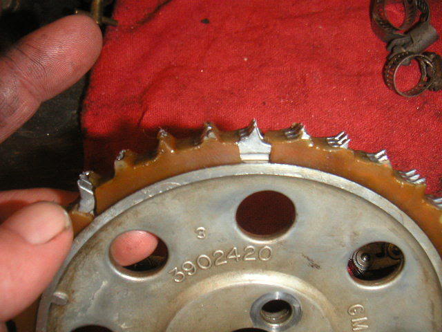
Chevy for years used NYLON gear teeth on aluminum gears, its not like they were concerned with getting the alignment correct to the last possible 2-5 thousands of an inch, they designed the timing sets to be easy to install and reasonably durable and run QUIETLY , and yes they eventually realized that was a HUGE mistake! but in this thread we are dealing with building an engine correctly, to gain all potential hp, and enhance durability here, not in merely allowing it to run once assembled
ny1.jpg

Timing_chain_comparison.jpg


RELATED INFO
viewtopic.php?f=52&t=1793&p=4553#p4553


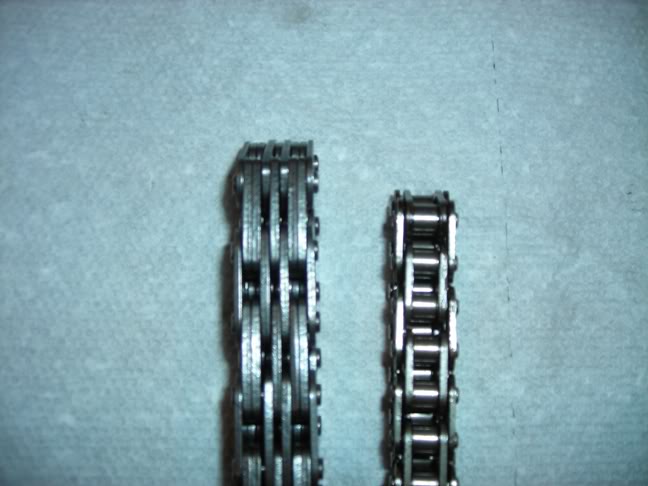
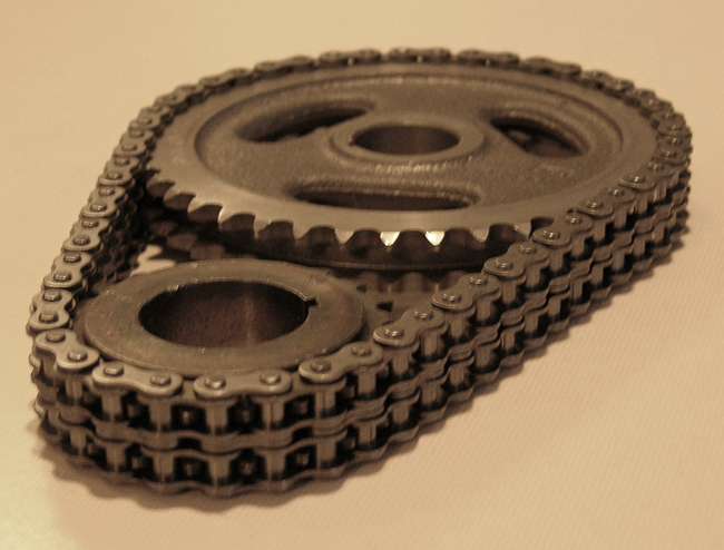
TRUE DOUBLE ROLLER TIMING CHAIN SETS FROM QUALITY MANUFACTURERS TEND TO BE MORE DURABLE

RollerTimingSet3513a.jpg


RollerTimingSet3518a.jpg


figure2-r2.gif

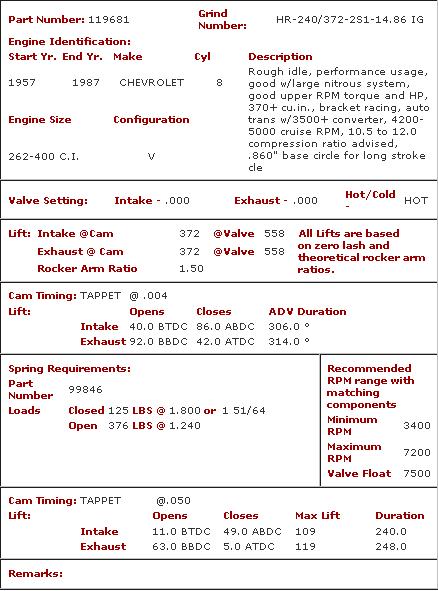
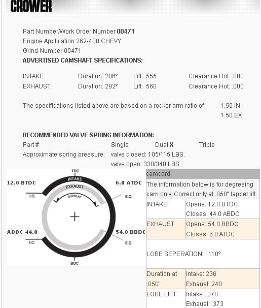
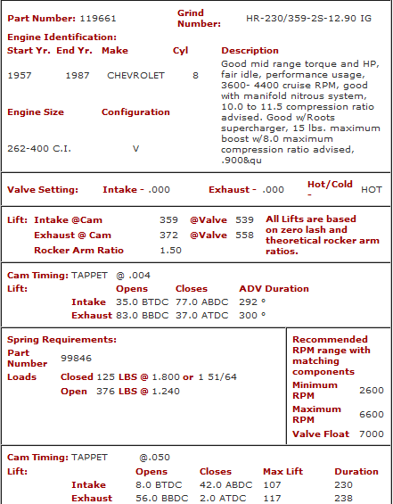
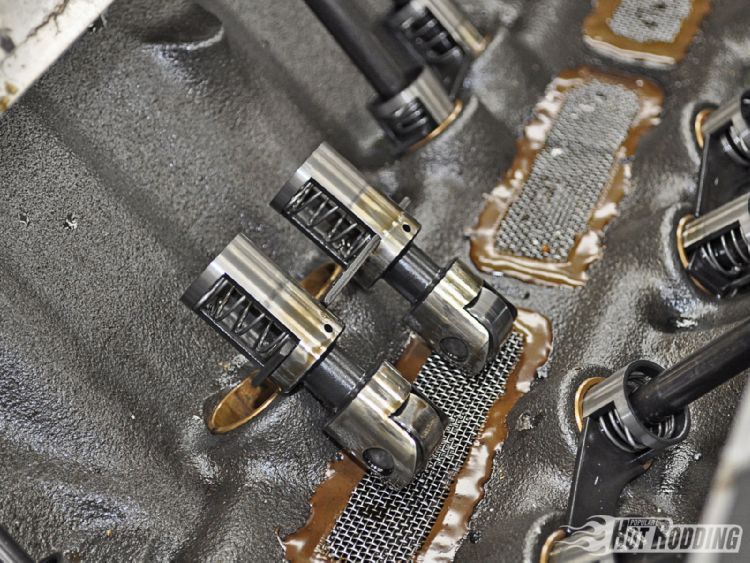
notice the more aggressive cam lobe acceleration rate on the roller cam lobes
figure5-5.gif

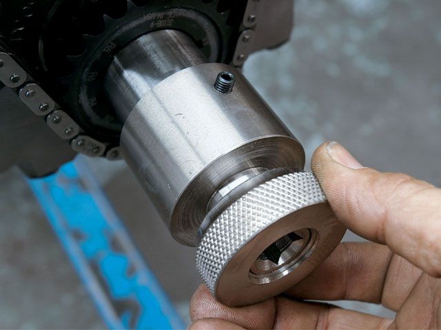
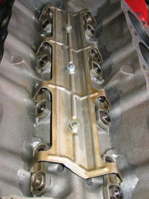
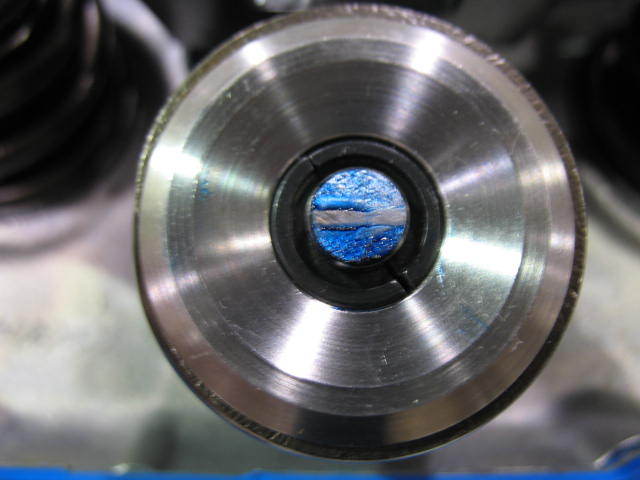
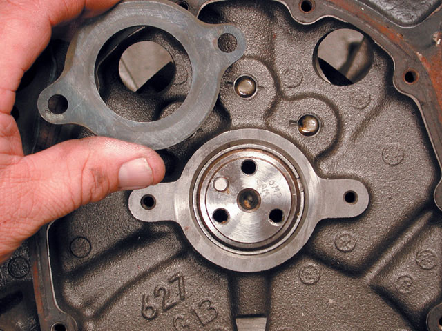
notice the stepped cam nose to fit retainer plate
225.jpg.png

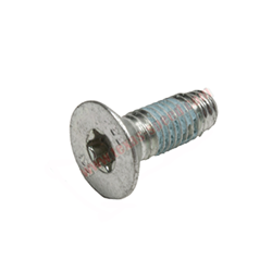
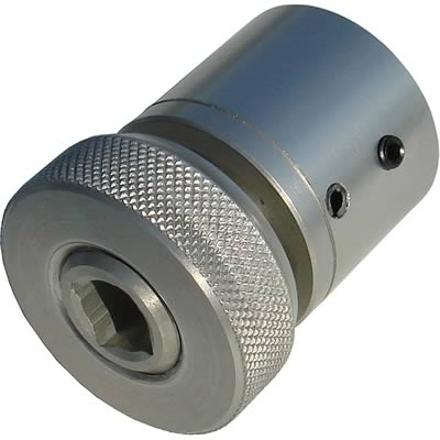
they usually use TORX SCREWS LIKE THIS on retainer plates
retainerplate.jpg


BTW IF your reading these threads READ THRU THESE RELATED LINKs

viewtopic.php?f=50&t=223&p=8024&hilit=damper+tool#p8024

viewtopic.php?f=52&t=966

viewtopic.php?f=52&t=90

viewtopic.php?f=52&t=196

viewtopic.php?f=52&t=399
 
I measured the distance thru the harmonic balancer and it is easily deeper than the distance to the gear. It will be pushing on the gear when tightening the balancer down.

BalancerProfProducts80001_w.jpg
 
Last edited:
Indycars said:
I measured the distance thru the harmonic balancer and it is easily deeper that the distance to the gear. It will be pushing on the gear when tightening the balancer down.


thats the case in 99% of engines, thats why you need a spacer or machine work done, thats why you measure carefully and use a cam button,if your goal is that your going to have to maintain perfect alignment once the dampers tightened on the crank snout if you want to maintain proper alignment
 
This sure is an eye opener. Currently I am using a stock balancer and plan on going with an after market product this winter. It would never have occurred to me to prefit the gear and balancer without the timing cover on.
 
Grumpy said:
keep in mind that the upper cam gear needs to have a cam button OR retainer plate and 5-8 thousands clearance with the cam timing cover to the cam button is suggested

This makes me think that you might be advocating the use of both a retainer plate and a cam button. The retainer plate in the statement above, is this the plate with tabs to lock the three bolts holding the gear to the camshaft. To clarify you only need one or the other, but not both......correct ???

I have the step nose camshaft so I'm using the retainer plate or sometimes called thrust plate.
 
if you have a retainer plate, obviously adding a cam button is just worthless extra work,
but I need to cover the vast majority of members, who currently use neither method to limit cam movement fore and aft in the cam journals in any answer posted
it should read....
"keep in mind that the upper cam gear needs to have a cam button OR retainer plate and 5-8 thousands clearance with the cam timing cover to the cam button is suggested"


INDYCARS
:mrgreen: your a HUGE BENEFIT HERE BECAUSE YOU BOTH TAKE GREAT PICTURES AND ASK GREAT QUESTIONS, PLUS YOU KEEP ME FROM POSTING VAGUE INFO OR ANSWERS
I went back and corrected/clarified that statement
 
HA! I KNEW IT ! YOUR LISTENING IN ON THAT 3AM CONVERSATION ALL WIFES HAVE< WHEN MY WIFE TALKS TO ALL THE OTHER WIFE'S where she tells ever other WIFE ABOUT HOW I SCREWED UP THE PREVIOUS DAY, and THEY DISCUSS HOW ALL THEIR HUSBANDS ARE CRAZY AND WHERE THEY GET ALL THE LATEST NEW IDEAS HOW TO MAKE ME CRAZIER!


BTW HAVE YOU MADE ANY MORE PROGRESS ON THE ENGINE ASSEMBLY?


I,m really hoping to see it assembled and running reasonably soon, as you've obviously done a truly exceptional and outstanding job on the prep and assembly
 

For my degree wheel pointer I wanted something that was substantial enough that I wouldn't
have to worry about bumping into it and having to start over. Instead of clothes hanger wire
at 0.075", I used some wire that I have that's 0.145" and mounted it in two places.

At first I used my finger and applied firm pressure to the lifter when it was on its way down,
but I found if I moved my finger around that the dial indicator would jump around as much
as 0.0008". So later I rotated the block, such that the lifter was nearly vertical. This seemed
to provide more consistent readings.

ReferencePointer1489.jpg
PointerAtZero1492.jpg


This is where I made sure I was parallel with the lifter movement in one geometric plane.


DialIndicatorSquare01_1499.jpg

And parallel to the other geometric plane.

DialIndicatorSquare02_1503.jpg
IndicatorAndLifter1496.jpg

I wanted to plot the Lift Curve and Velocity Curve. The Lift Curve is created by measuring
the lift every 2 degrees; the Velocity Curve is calculated from the lift numbers. This required
about 170 measurements for each lobe. Since I went back and using what I had learned from
the previous measurements, I made a second pass on the intake lobe to improve my accuracy.
In total I took over 500 data points.

As I took the measurement and recorded them in a program called Excel, I also had Excel
calculate the Lifter Velocity. This turned out to be a great help to me. It was easy to confirm
that I was inputting the lift numbers correctly. The Velocity numbers should make a smooth
progression from zero up to max and back to zero (Columns C, E & G in Excel Table). If I
transposed a couple of numbers, the velocity number would be drastically different from the
previous value.

ExcelData01.JPG

If you look at the lift curve below it doesn't look like there is much difference between the
2 passes I made recording the lift numbers for the intake lobe. Notice how the Blue intake
curve is hidden by the Green intake curve. But look at the second graphic below to see how
my accuracy really shows up in the velocity curve.

LiftCurveCrowerHR00471_02.jpg


You can see from the graphic below how I improved from the first time I recorded lift
numbers for the intake lobe and the second time. Note the three highlighted areas.

VelocityCurveOverlayHR00471.jpg

If we had this kind of information done in a standardized way (Graphic Below), one could really
compare camshafts between the different manufactures. Using the few numbers they provide
only give you a partial picture of how the camshaft will really perform.

An interesting note about the two types of curves shown below. The Point Of Inflection on
the Lift curve is the peak of the Velocity curve (Note 1st & 3rd vertical purple lines on the
intake plot). Where the velocity curve crosses the zero horizontal axis, is the same place
the lift curve peaks (Note the 2nd vertical purple line).

Lift&VelocityCurveCrowerHR00471_02.jpg

I think Wikipedia describes the Inflection Point best.

If one imagines driving a vehicle along a winding road, inflection is the point at which the
steering-wheel is momentarily "straight" when being turned from left to right or vice versa.

http://en.wikipedia.org/wiki/Inflection_point

Animated_Inflection_Point.gif

The link below will download my Excel spreadsheet file if you want to look closer at my
numbers or you could enter your own numbers to see how your camshaft curves look. The
only numbers you will want to change are on the Data sheet in columns B, D and F, all
others numbers are calculated or they never change such as the Crankshaft Degree. Click
on Data tab at the bottom of the window when you want to enter your numbers.

ExcelDataSheets01.JPG

Download the Excel File Below:


Previous Version Downloaded 3 times.


Attachments

  • LiftCurveCrowerHR00471_02.xlsx
    94.2 KB · Views: 7
Last edited:
WOW!

now its is obvious why it took some time between your last post and this one!

I wish I had 20% of your computer graphic skills and 50% of your patients , while Ive degree-ed in numerous cams Ive never had the ability to post that detailed info that,s so time intensive to acquire and impressive, on cam lobe ramp velocity and / or produce the graphic info, thats truly amazing work.

keep in mind that cam and heads etc. were selected as a good compromise between drive-ability for street/strip use and maximum available horsepower and torque in a useable rpm range, it will produce both a responsive engine and one that makes impressive mid range torque and a very useable power curve, most guys make the common mistake of thinking impressive peak horsepower is the goal, and then find they have built an engine thats almost useless for driving on the street, where they really spend the vast majority of their time driving
 
grumpyvette said:
WOW!

now its is obvious why it took some time between your last post and this one!
About 2-1/2 hours for each lobe, just to record the data points. That was hardest part, kinda boring after awhile doing the same thing 500 times.


I would really like to compare the area under the lift curve between the Crower 00471 that I have and your other favorite the Crane 119661.


Crower00471.JPG
Crane_119661.JPG
 
Last edited:
Every component selected is a compromise in some respects, your combo will require a cam in the 230-245 intake duration range if you intend to have both some reasonable ability to perform as BOTH a street driven, an brisk track performance modes , naturally the more duration you use the higher in the rpm band you can expect to make peak power and the greater the loss in off idle and low rpm torque. but a really useable compromise giving a good compromise at both ends of the power curve can be achieved to some degree.
Ive got a couple dozen or more cams I have used frequently in engine builds,each in its own type of engine, theres no real favorites, I look at what matches the application best, but there are several that have proven to be exceptional performers in certain classes of engines, and some that perform well but might have minor objectionable characteristics in some part of the rpm range if used , especially if the gear ratio or car weight is a marginal match.
notice below theres three cams that are not all that much different in lift or duration or LSA ,yes theres obvious changes and each has a slightly different power curve, but its not peak power but how the engine behaves in the low and mid rpm band thats more important in a street/strip car, most guys concentrate on peak hp, forgetting that they spend 95% of the engines life at well under that rpm range

example
a crane 119681 in your application would boost peak horse power noticeably, but it would not be ideal in traffic
119681.jpg


http://www.cranecams.com/product/cart.p ... il&p=24190


the crane 119661 I use is much better in traffic or cruising than the 119681 but its down on peak power, the crower 00471,
00471.jpg


is a really good compromise having much of the benefits and just a bit of the less desirable characteristics making it a better choice in your application in my opinion
http://www.cranecams.com/product/cart.p ... il&p=24188
c119661.png
 
file.php


WHEN I saw this I cringed , Ive never done that, but I have use a NICKLE with a 1/4" hole drilled in the center set on top of a lifter to center and hold a push rod on the lifter, during the cam degree process, before so if what your doing works your fine


CCA-4926.jpg

cam_checker1.jpg

obviously buying a tool similar to this is a waste of money if you are not going to consistently be building engines but the drilled NICKLE to set on the lifter during the degree process might be a good option as it takes only a few seconds and your only out 5 cents

degreewheeladapter.jpg

viewtopic.php?f=52&t=1759&p=4441&hilit=degree+tools#p4441
ctrp_1012_01+race_engine_rebuilding_tips+.jpg


camposition.jpg


yes it takes more time and effort to do correctly and some tools but it generally helps power and durability

pro-67491_w.jpg


http://www.summitracing.com/parts/PRO-67492/

http://www.summitracing.com/parts/PRO-67491/
 
grumpyvette said:
WHEN I saw this I cringed , Ive never done that, but I have use a NICKLE with a 1/4" hole drilled in the center set on top of a lifter to center and hold a push rod on the lifter, during the cam degree process, before so if what your doing works your fine

Did you use a nickel on roller lifters with a tie-bar ??? When I look at a nickel on one of my lifters, it doesn't sit very stable/flat.

Sorry didn't mean to scare you! :lol:

DSC01506.jpg


I got the idea from this SA21 "Engine Blueprinting" by Rick Voegelin on page 132 where he suggests using the edge of the lifter. I did keep an eye on contact point with the lifter, the indicator tip always seemed to be in the same place.

SA21_EngineBlueprinting.jpg
 
Last edited:
You make an excellent point, and as always your ability to take and post excellent quality photos makes illustrating , asking the question, and showing whats involved really great to deal with I see your hydraulic lifters seem to be built a bit differently,
heres several designs that DO seem to work with the nickle idea ,Ive used in the past


31WT41MMV4L._SL500_AA300_.jpg

148_0307_roller_3_z.jpg

BlockRollervalley.jpg

valvetrain_components+valvesprings.jpg


but I long ago just bought the tool and before that Id used a solid lifter that Id machined and brazed a plug on the top of a spare lifter I kept in my cam degree tool kit for cam degree work.
CCA-4926.jpg

cam_checker1.jpg


but I don,t see where it won,t work in your application, while its very true that the nickle will not seat as if its centered due to its larger diam. its also true that the push rod centered in the hole drilled in the nickle, as it sits on the lifter being held in place, by the weight of the push rod set in the push rod guide plate seems to hold it in place, in your case, a 1/4" fender washer, a dime,. or penny thats drilled might be a better choice, the obvious goal is a push rod seat that rides on the lifter thats not effected with lifter seat movement, so obviously the correct tool is optimal but I can,t see spending cash on a one time deal either


WHILE WE ARE DISCUSSING THIS Id point out that theres a dozen or more hydraulic roller lifter designs, most stick up well past the top of the lifter bores when the cam has the lifter riding on the cam lobes base circle, of course small base cams tend to have the lifters sit a bit lower in the bores and you can not generally measure with some designs with the link in place because the top of the lifter drops to below the upper link surface
p1050168i.jpg


p1050165v.jpg


related info


viewtopic.php?f=52&t=1489

viewtopic.php?f=52&t=3810&p=10200&hilit=+small+base+cams#p10200

viewtopic.php?f=52&t=3802&p=18031&hilit=+small+base+cams#p18031

viewtopic.php?f=52&t=181

viewtopic.php?f=52&t=90
 
I need to order a adjustable pushrod so I can determine the correct length for the correct valvetrain geometry.

I'm thinking since the stock length is 7.794" and I should need something shorter, then one of these should work. The Dart SHP block takes a .300" taller lifter, but I'm not sure if that also raises the pushrod cup .300" or is it's overall length just longer.

CompCams
7905-1 .........6.125" 7.500"..........$13.95
http://www.summitracing.com/parts/CCA-7905-1/

7702-1......... 6.800" 7.800".........$18.95
http://www.summitracing.com/parts/CCA-7702-1/

For a few dollars more the second checking pushrod looks like the better idea, since you can determine it's length directly. Evey full turn is 0.050".

The pictures below are shown with the stock pushrod installed and the rockers are just sitting there with no preload. Also both lifters are on the base circle. There is only a few thread showing thru the rocker.

So would either one of the pushrod checkers above be in the correct range to get the right geometry ???

PushrodLengthCheck1510.jpg
ValveTip-RockerRoller1516.jpg


Last edited:
ValveTip-RockerRoller1516.jpg

ONCE AGAIN YOUR PHOTO AND POSTING SKILLS ARE AMAZING

the second checking push-rod looks like the better idea, just looking at the pictures its rather obvious that the push rod needs to be a bit shorter but Id bet it falls well within that 6.800"-7.800" range, looking at it Id think close to 7.500"-7.600" but obviously the process of finding the correct length push rods not that difficult, you install the correct push rod checker for your application,on a rocker stud, install the adjustable push rod, in place of the stock push rod after roughly adjusting the adjustable push rod to the stock length once the cam is rotated so the lifter, your using to verify the correct length is resting on the cams base circle, and then you extend or shorten the adjustable push rod so the plastic push rod checker just rests on both the tip of the valve stem and the push rod checker as in the picture above, this gets you very close to the correct length, you then use the machinists blue or a magic marker and the rockers you will be using to determine the exact correct length by centering if possible but finding the minimum sweep mark width so the wear mark on the valve tip as close to the valve stem center line as you can get it and the minimum side loading on the valve stem is found. centering the mark is less important than minimizing the rocker tip wipe mark width.
be sure you get a push rod checker designed to fit your rocker stud diam. (3/8" or 7/16")
http://www.summitracing.com/parts/CCA-7702-1/
viewtopic.php?f=52&t=1376&p=3030&hilit=pushrod+length+checker#p3030
auto0075kn.jpg


Proper push rod length is absolutely critical for peak performance—minimizing bent or broken valve stems, guide wear, and energy-wasting valve side-loading friction.
With the lifter located on the round base circle, position the Push Rod length Checker (make sure you have the Checker with the proper diameter hole) over the stud. Ideally the Checker should contact the top of the push rod and the valve tip evenly at the same moment, should the Checker contact the push rod first, measure the gap between the front of the checker and the valve tip, and purchase a shorter push rod of the correct length. Should the Checker contact the valve tip first, measure the gap between the back of the Checker and the top of the push rod, and purchase a longer push rod.
 
grumpyvette said:
you then use the machinists blue or a magic marker and the rockers you will be using to determine the exact correct length by centering if possible but finding the minimum sweep mark width so the wear mark on the valve tip as close to the valve stem center line as you can get it and the minimum side loading on the valve stem is found. centering the mark is less important than minimizing the rocker tip wipe mark width.

I should have stated that the copper head gasket ( compressed 0.021") was not installed when the pictures were taken. Everything in the head....rocker arm studs (7/16") and head bolts are only snugged. I assumed this would not make a big enough difference, to warrant the extra work to determine which pushrod checker to order. The head gasket WILL be there during the actual checking process.

Concerning your statement above......how can you measure the sweep mark on the valve tip accurately enough to determine the width and centering on the valve stem. That's nothing like measuring a journal diameter, much harder to measure the width of a rub mark on the valve. This seems to me is a visual determination, not something you can measure with my resources anyway......maybe at Penske they could.

Now......do you factor in how much the lifter cup is depressed (pre-loaded), when the valve train is in a operational condition, to determine the correct pushrod length to order ???


Indycars said:
grumpyvette said:
you then use the machinists blue or a magic marker and the rockers you will be using to determine the exact correct length by centering if possible but finding the minimum sweep mark width so the wear mark on the valve tip as close to the valve stem center line as you can get it and the minimum side loading on the valve stem is found. centering the mark is less important than minimizing the rocker tip wipe mark width.

I should have stated that the copper head gasket ( compressed 0.021") was not installed when the pictures were taken. Everything in the head....rocker arm studs (7/16") and head bolts are only snugged. I assumed this would not make a big enough difference, to warrant the extra work to determine which pushrod checker to order. The head gasket WILL be there during the actual checking process.

Concerning your statement above......how can you measure the sweep mark on the valve tip accurately enough to determine the width and centering on the valve stem. That's nothing like measuring a journal diameter, much harder to measure the width of a rub mark on the valve. This seems to me is a visual determination, not something you can measure with my resources anyway......maybe at Penske they could.

Now......do you factor in how much the lifter cup is depressed (pre-loaded), when the valve train is in a operational condition, to determine the correct pushrod length to order ???


when setting up the valve train geometry , your not AS concerned with centering the rub mark on the valve stem tip,as you are in minimizing its width, visually judging will allow you to get close enough.

valvetip.jpg


"Now......do you factor in how much the lifter cup is depressed (pre-loaded), when the valve train is in a operational condition, to determine the correct pushrod length to order ???"


Ive found thats not critical, just assume the lifters push rod seat is nearly fully depressed because the oils mostly squeezed out by full lift anyway


BTW I JUST TOOK THE TIME TO RE_READ THIS THREAD< ITS A VIRTUAL CLASS IN ENGINE ASSEMBLY THAT SHOULD BE READ BY EVERY LAST MEMBER
viewtopic.php?f=69&t=3814&p=18361#p18361
THESE THREADS SHOULD HELP

viewtopic.php?f=52&t=1376&p=3030&hilit=pushrod+length+checker#p3030

viewtopic.php?f=52&t=181
 
Back
Top