geometry and clearances in the photos looks good!
You are using an out of date browser. It may not display this or other websites correctly.
You should upgrade or use an alternative browser.
You should upgrade or use an alternative browser.
TBucket Engine Project (Dart SHP)
- Thread starter Indycars
- Start date
Thanks for those especially nice words above!grumpyvette said:geometry and clearances in the photos looks good!
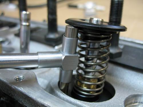
The valve spring retainer To valve stem seal clearance is going to be close to the minimum of 0.060".
The Crane valve stem seals are a minimum of .010" shorter than the Brodix seals that came with the IK200 heads. The Brodix seal varied from .515" - .525" and the Crane seals varied from .499" .505". The highest Crane seal was .505", therefore I can assume a additional clearance of 0.010" added to the 0.053" shown in the picture, for a total of 0.063".


I just realized that I can't use those numbers. It really comes down to how far above the valve guide the seal extends, NOT their overall height. I suppose that's the good part of working thru these numbers, it often brings to light a misunderstanding.
Last edited:
my wife just walked over and asked me why I was laughing out loud, I pointed to your statement..."I suppose that's the good part of working thru these numbers, it often brings to light a misunderstanding. "
and THEN had to explain.... that thats how every last guy learns about the fact...... that you need to measure and never assume clearances are what you think they should be,.... but rarely are!
YOUR DOING EXCEPTIONALLY GOOD WORK! and TAKING THE TIME TO DO THINGS CORRECTLY, ITS REFRESHING TO SEE THINGS BEING DONE RIGHT VS THE FAR MORE COMMON ROUTE GUYS TAKE OF SLAPPING PARTS TOGETHER AND THEN WONDERING WHY THINGS JUST DON,T WORK ONCE ASSEMBLED
the firm rule is
ASSUME EVERYTHING NEEDS TO BE MEASURED SEVERAL TIMES and KEEP A FEW RECORDS
actually measuring clearances helps a great deal[/b]

in an ideal world youll want .090 clearance between the lower retainer and upper valve guide but .060 will work in most cases
and THEN had to explain.... that thats how every last guy learns about the fact...... that you need to measure and never assume clearances are what you think they should be,.... but rarely are!
YOUR DOING EXCEPTIONALLY GOOD WORK! and TAKING THE TIME TO DO THINGS CORRECTLY, ITS REFRESHING TO SEE THINGS BEING DONE RIGHT VS THE FAR MORE COMMON ROUTE GUYS TAKE OF SLAPPING PARTS TOGETHER AND THEN WONDERING WHY THINGS JUST DON,T WORK ONCE ASSEMBLED
the firm rule is
ASSUME EVERYTHING NEEDS TO BE MEASURED SEVERAL TIMES and KEEP A FEW RECORDS
actually measuring clearances helps a great deal[/b]
in an ideal world youll want .090 clearance between the lower retainer and upper valve guide but .060 will work in most cases
Now that I know the correct length, it's time to order the pushrods. But what do I need....what materials, straight or tapered, larger wall thickness, maybe a larger diameter of 3/8", up from the stock 5/16".
Lifter acceleration and spring pressures will have a large factor on what I need.
Camshaft:
Crower 00471 Hydraulic Roller
550/555 lift & 236/240 Duration @ .050 (CompCams Rockers are 1.52 Ratio, .562/.567 Lift)
Springs: (CompCams CC987)
Seat Pressure = 121 lbs ( This number came from the Brodix document )
Open Pressure = 331 lbs (Spring Rate 370 lbs/in)
(.567 x 370) + 121 = 331 lbs
I did find this chart for pushrod parameters, but relating this to camshaft and spring pressures is NOT obvious.

Prices range from $50 to nearly $300. All the info from the manufactures is mainly marketing terms, nothing tells me what I really need for my application. From what I've read lately, pushrods are a lots more important than what was believed 10 years ago.
I'm thinking these should work for $144 at Summit
http://www.compperformancegroupstores.c ... 16HighTech
Any suggestion or comments ???
Last edited:
Well that's nice, I get to be your Sunday afternoon entertainment!grumpyvette said:my wife just walked over and asked me why I was laughing out loud, I pointed to your statement..."I suppose that's the good part of working thru these numbers, it often brings to light a misunderstanding. "
and THEN had to explain.... that thats how every last guy learns about the fact...... that you need to measure and never assume clearances are what you think they should be,.... but rarely are!

http://www.summitracing.com/parts/TFS-21407450/
save a few $$$$$
Ive used several DOZEN sets of these in various lengths with zero problems over the last 10 years
save a few $$$$$
Ive used several DOZEN sets of these in various lengths with zero problems over the last 10 years
From reading this article on the CompCams website, it would appear that it's hard to order the correct length between manufactures, since they don't all measure pushrods the same way.grumpyvette said:http://www.summitracing.com/parts/TFS-21407450/
save a few $$$$$
Ive used several DOZEN sets of these in various lengths with zero problems over the last 10 years
Would you anticipated any problem between CompCams who made the pushrod checker that I used and TrickFlow's pushrods ???

Last edited:
heres trickflows Phone number, Phone:
330-630-1555
Ive always just asked, the manufacturers when I have questions like that ,
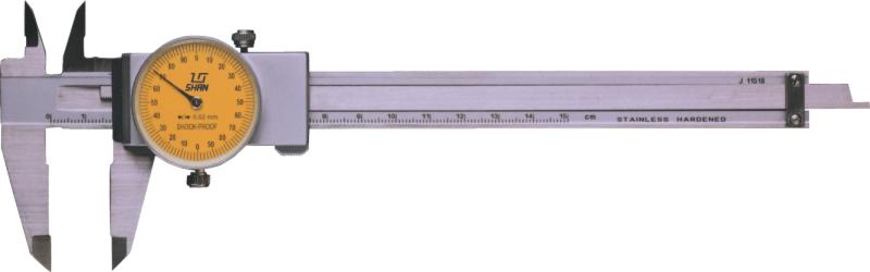
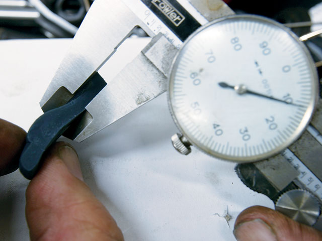
because Im not really sure, I measure push rods ACTUAL LENGTH , the length between the caliper jaws on my caliper with the adjustable test fit push rod at the required length, once I've found it with this 12" caliper and never had problems ordering trickflows push-rods that way, but it always pays to ask, before spending money, the truth is that theres some ability to compensate for minor variations thru lifter pre-load, lash caps, retainer, and keeper changes so if your within .050 you can most likely get bye, and if your within .020 its fine in most cases, and yes you should do your very best to avoid needing to compensate here, but its generally not the end of the world if you screw up ( being ABSOLUTELY PERFECT ) and find your .010-.020 long or short from the ideal length

http://www.harborfreight.com/12-inch-di ... 47261.html
or
http://www.google.com/products/catalog? ... CHoQ8gIwAA
330-630-1555
Ive always just asked, the manufacturers when I have questions like that ,
because Im not really sure, I measure push rods ACTUAL LENGTH , the length between the caliper jaws on my caliper with the adjustable test fit push rod at the required length, once I've found it with this 12" caliper and never had problems ordering trickflows push-rods that way, but it always pays to ask, before spending money, the truth is that theres some ability to compensate for minor variations thru lifter pre-load, lash caps, retainer, and keeper changes so if your within .050 you can most likely get bye, and if your within .020 its fine in most cases, and yes you should do your very best to avoid needing to compensate here, but its generally not the end of the world if you screw up ( being ABSOLUTELY PERFECT ) and find your .010-.020 long or short from the ideal length
http://www.harborfreight.com/12-inch-di ... 47261.html
or
http://www.google.com/products/catalog? ... CHoQ8gIwAA
well how close are you to installing the engine in the car?
Long ways from installation yet. I'm still doing pre-assembly checks. The paint going on this engine is not your ordinary paint job either. I'm experimenting with the Por15 Engine Enamel, Tie-Coat Primer, Ready Prep and their Marine Clean on a sample piece of metal now. The block has been ground fairly smooth all over the exterior, so I'm wanting a really smooth looking paint.grumpyvette said:well how close are you to installing the engine in the car?
I'm hoping for something similar to this engine !
(Page little over 1/2 down the page until you get to "DRESSING THE BLOCK")
http://www.precisionenginetech.com/proj ... d-part-1/#


After the engine is done, I need to rebuild a 200-4R trans. Which will require a modification to the transmission mount since I'm changing from a TH350 to 200-4R. An automatic is something I've never been inside of before, so it will also be a slow process of learning and doing all over again. The 200-4R means I will have to worry about the TVR cable and getting it right is very important.
To answer your question.........maybe next summer. Thank god I have a heated garage !!!
Last edited:
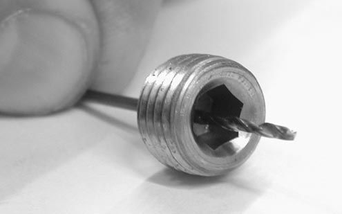
The Dart SHP block does NOT have holes like the original Chevy block for oil to drain from the valley back to the oil pan.
Will drilling just one oil gallery plug with a 0.030" hole, provide enough oil to the timing gear and chain??? Maybe there should be two plugs with 0.030" hole or one with a 0.044" hole. The one larger hole would be easier to drill.

Will drilling just one oil gallery plug with a 0.030" hole, provide enough oil to the timing gear and chain??? Maybe there should be two plugs with 0.030" hole or one with a 0.044" hole. The one larger hole would be easier to drill.
Last edited:
mathd
solid fixture here in the forum
I also have a heated garage since this year, not as hudge or as nice as yours or grumpy's but oh well.. i can work in t-shirt while its snowing outside what a great feeling, dont have to rust the job, can take time and open some beer.. :twisted: Am starting to like this stuff way too much.
It would be very hard to get a project done in Canada if you didn't have a heated garage. How many months of the years can you work without heat....... 4-5 months maybe ???mathd said:I also have a heated garage since this year, not as hudge or as nice as yours or grumpy's but oh well.. i can work in t-shirt while its snowing outside what a great feeling, dont have to rust the job, can take time and open some beer.. :twisted: Am starting to like this stuff way too much.
just drill a single plug,with the .030 drill bit (the pass side oil gallery) a .025-.031 hole it will provide a bit extra lubrication without causing a problem with your oil pressure, just be aware of that drill size, basically a 1/32"-#72 drill, so use a drill press and take your time those bits are easy to break
You say a bit of extra lubrication, but the oil coming thru the plug will be the only lubrication that I'm aware of.grumpyvette said:just drill a single plug,with the .030 drill bit (the pass side oil gallery) a .025-.031 hole it will provide a bit extra lubrication ......
BTW, the oil pump is a Melling 10552, 10% over volume.
Edit: I always think better after I have made a public statement. There would be some oil coming from the cam bearing behind the cam gear.
mathd
solid fixture here in the forum
Well, usually from mid april to end of october and it can be comfortable considering the weather we had this and the last 2 years.Indycars said:It would be very hard to get a project done in Canada if you didn't have a heated garage. How many months of the years can you work without heat....... 4-5 months maybe ???mathd said:I also have a heated garage since this year, not as hudge or as nice as yours or grumpy's but oh well.. i can work in t-shirt while its snowing outside what a great feeling, dont have to rust the job, can take time and open some beer.. :twisted: Am starting to like this stuff way too much.
Working outside laying on the snow/ice with frozen tool/car component is not always nice.. If you ever worked on a car with wet clothes when your finger are frozen because of the cold steel because you dont like working with gloves anyway, you know what i mean, or when your working alone in the wild and you need to repair the leak on the diesel because it wont start again if the engine cools too much and some (under -30°C) oil/fuel leak on your hand and you need to keep going with that cold steel (that last one was not me but a friend's story of last winter) omg :/. That what happen when you live far from the big city and closer to the north.
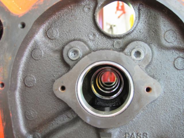
your forgetting that the front cam bearing leaks a constant drip of oil as the front journal spins in the bearing, its not a great deal but it by design leaks and also by design sloshing oil when you hit the brakes tends to lube the lower cam gear and chain, and due to the spinning crank assembly theres always a constant oil mist to help lubrication present in the oil pan
BTW PLEASE REPOST THAT LINE where you realize the front cam bearing leaks oil I some how accidentally deleted it when trying to quote your post
BTW PLEASE REPOST THAT LINE where you realize the front cam bearing leaks oil I some how accidentally deleted it when trying to quote your post
Ok I've been living dangerously again this weekend.....I've been thinking !
I wanted to check the piston to valve clearance (PTVC), but with hydraulic lifters this is not a sure thing. The lifter could be compressing during the check, rendering my measurement invalid.
I could use my dial indicator with light checking springs to find the Total Valve Clearance (TVC) by pushing the valve down by hand until it touches the piston at the correct crankshaft angle. But this was only part of what I needed, what was the Valve Lift (VL) at this crankshaft angle? That's when the light went on for me. I had plotted the lift curve every 2 degrees, so I knew very accurately what the valve was doing. I am also aware that any error measuring the lobe lift would be magnified by the rocker ratio. For example, if I had an error of .002" and my rocker ratio is 1.52, then valve lift error would be .003".
Please read thru my steps below and see if my process for checking PTVC is valid, I'm wide open to discussion. If it proves to be valid, then I will go back and take measurement from 30 BTDC to TDC for the exhaust valve and TDC to 30 ATDC for the intake valve. At this time I've only taken one measurement at 10 ATDC with the intake valve.
This is the process that I used.
1. Determine TDC and set the degree wheel.
2. Rotate crankshaft clockwise, stopping on 10 degrees ATDC.
3. Push down on intake valve stem until it touches the piston.
4. Take reading from dial indicator and record measurement. (TVC = .330" )

5. Go to the table for 10 ATDC for intake, record the Lobe Lift (LL = .132" )

6. The lift value of .132" is the Lobe Lift, we want the Valve Lift, therefore we have to multiply by the rocker ratio.
In my setup the ratio = 1.52,
Valve Lift = .132" x 1.52 = .200" ( VL @ 10 ATDC )
7. Now we need to take the Total Valve Clearance (TVC) and subtract the Valve Lift (VL), therfore:
Valve To Piston Clearance VTPC = TVC - VL
VTPC = 0.330" - 0.200"
VTPC = 0.130"
( Minimum VTPC should be no less than 0.100", therefore I'm good with an additional 0.030" )
This only tells me the valve face to piston clearance, but nothing about the valve radial clearance, that's another check to be peformed.
At this time the cam is installed 4 degrees advanced or dot-to-dot. I have not made my decision yet about retarding the cam 2-4 degrees, but would need to decide this before taking any final measurements.

Last edited:
your doing excellent technical work, I see no fault there, in fact of all the people Ive seen work on engines your probably the only person I know that Id would have building engines for my personal use if i could not build my own, because i know your taking all the time and effort to do everything I generally do, and in a few areas even a bit more at tiimes.
Ok back to the question at hand, let me point out that by the time the lobe and lifter rotate that far, lifting the valve against spring resistance, most if not all the slack in the valve train and lifter seat movement have changed so your not looking at nor are you likely too see any huge difference in lifter seat movement that might result in less clearance, , but correctly checking basically comes down to the fact that it requires checking piston to valve clearance by physically checking reality vs theory and thats best done with clay on the piston and careful measurement with a caliper, I think your doing everything correctly but making things a bit more difficult and complex that required,I've got a program that does exactly what you've done in my engine analyzer pro software
http://performancetrends.com/Engine-Analyzer-Pro.htm
I've tried for years to get it to work, and while its fun and intriguing/and frustrating to play with , (knowing IM hardly the best computer guy) Ive always resorted to clay strips and rotating the engine and measuring clearances and yours appear to be fine so far, but Id still suggest using the clay and checking theory vs fact! if the clay never gets thinner than .100 after several rotations of the engine with the rockers set correctly like you did measuring the valve tip when selecting push rod length you should be fine.
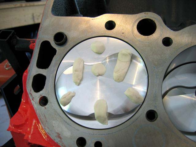
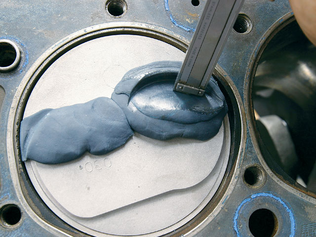
if your using the low pressure check springs its best to roll clay into several 1/4" diam. 3" long strips, resembling soda straws and lay several parallel across the piston valve notches as its far easier to compress that a solid layer of clay. strips tend to work better than small blobs like this picture below, spray both the piston and clay strips with WD40 to prevent sticking
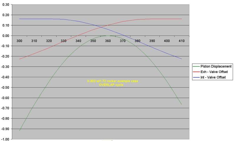
GRAPH SHOWING VALVE AND PISTON LOCATION, ,USUALLY AT ITS CLOSEST BETWEEN 10-20 DEGREES BFTDC and USUALLY AT ITS CLOSEST BETWEEN 10-20 DEGREES AFTDC
viewtopic.php?f=52&t=399

Ok back to the question at hand, let me point out that by the time the lobe and lifter rotate that far, lifting the valve against spring resistance, most if not all the slack in the valve train and lifter seat movement have changed so your not looking at nor are you likely too see any huge difference in lifter seat movement that might result in less clearance, , but correctly checking basically comes down to the fact that it requires checking piston to valve clearance by physically checking reality vs theory and thats best done with clay on the piston and careful measurement with a caliper, I think your doing everything correctly but making things a bit more difficult and complex that required,I've got a program that does exactly what you've done in my engine analyzer pro software
http://performancetrends.com/Engine-Analyzer-Pro.htm
I've tried for years to get it to work, and while its fun and intriguing/and frustrating to play with , (knowing IM hardly the best computer guy) Ive always resorted to clay strips and rotating the engine and measuring clearances and yours appear to be fine so far, but Id still suggest using the clay and checking theory vs fact! if the clay never gets thinner than .100 after several rotations of the engine with the rockers set correctly like you did measuring the valve tip when selecting push rod length you should be fine.
if your using the low pressure check springs its best to roll clay into several 1/4" diam. 3" long strips, resembling soda straws and lay several parallel across the piston valve notches as its far easier to compress that a solid layer of clay. strips tend to work better than small blobs like this picture below, spray both the piston and clay strips with WD40 to prevent sticking
GRAPH SHOWING VALVE AND PISTON LOCATION, ,USUALLY AT ITS CLOSEST BETWEEN 10-20 DEGREES BFTDC and USUALLY AT ITS CLOSEST BETWEEN 10-20 DEGREES AFTDC
viewtopic.php?f=52&t=399
grumpyvette said:your doing excellent technical work, I see no fault there, in fact of all the people Ive seen work on engines your probably the only person I know that Id would have building engines for my personal use if i could not build my own, because i know your taking all the time and effort to do everything I generally do, and in a few areas even a bit more at times.
Wow, thanks Grumpy, I'm humbled by your comments!
let me point out that by the time the lobe and lifter rotate that far, lifting the valve against spring resistance, most if not all the slack in the valve train and lifter seat movement have changed so your not looking at nor are you likely too see any huge difference in lifter seat movement that might result in less clearance,
When the lifter compresses, then that is a direct reduction in valve lift. Therefore this would effect the PTVC by the same amount that the lifter compresses. What am I not getting?
I did put the modeling clay in and turn the engine over at least two revolutions. Removed the clay and placed it in the freezer for a few minutes, then cross sectioned and measured. I got 0.220" on the intake.
I must be doing something different than you. Maybe with light checking springs I need to turn the motor over 10 times to fully compress the clay, since they may not be strong enough to compress the clay in one stroke. But this would NOT compensate for the lifter compression. The spring in the lifter has to compress BOTH the valve spring and the clay.