You are using an out of date browser. It may not display this or other websites correctly.
You should upgrade or use an alternative browser.
You should upgrade or use an alternative browser.
TBucket Engine Project (Dart SHP)
- Thread starter Indycars
- Start date

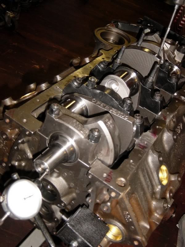
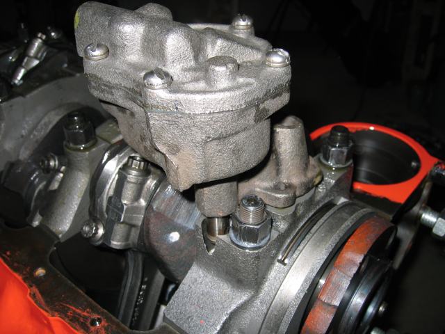
Indycars said:I did find this spot where the clearance is abit tight. If I lost the thrust bearing there
might be a problem, but it's the other side that is most likely to fail.
What do you think, is there a problem here ???
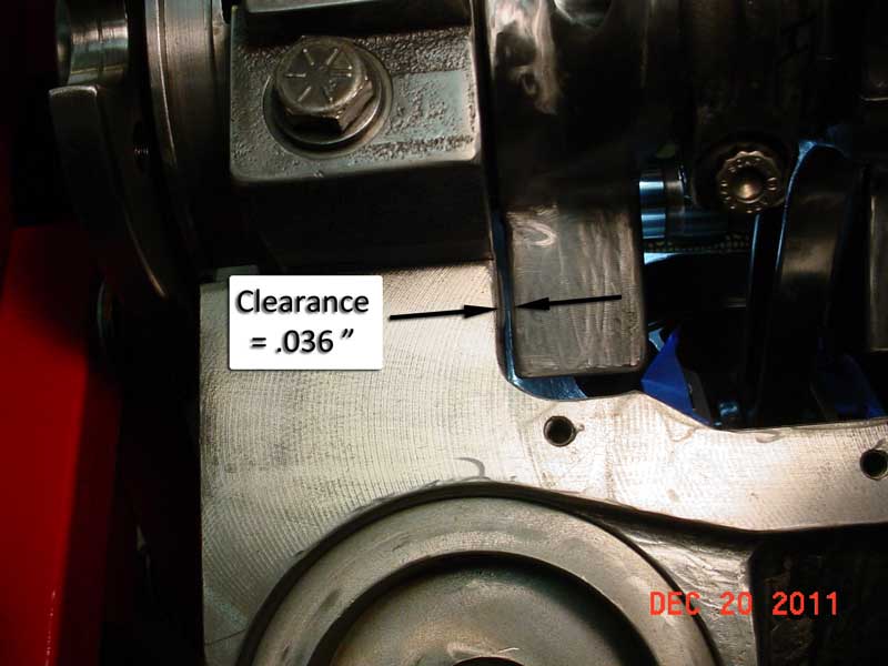
youve got no problems, thrust bearing clearance allows less than 1/3rd of that movement or clearance your measuring , so its never going to be a problem
Below is the wear pattern between the distributor gear and cam gear. It's not centered, but shifted towards the bottom end of distributor.

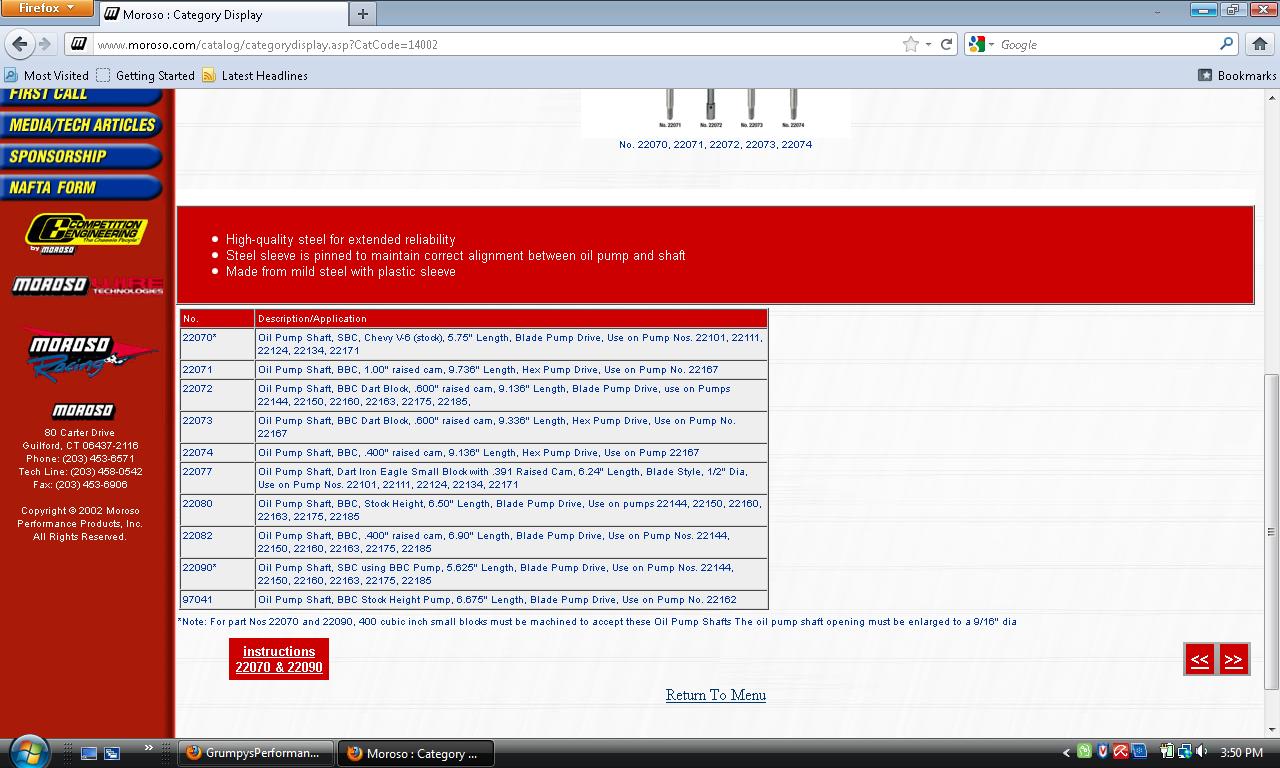
The oil pump drive shaft has an end play of .156", which seems like a lot. The end play is enough, that it exposes the slot in the oil pump.


BTW, all gaskets were in place and components were snugged down, but not torqued.
Head Gaskets, Intake Manifold Gaskets, Distributor Gasket
The oil pump drive shaft has an end play of .156", which seems like a lot. The end play is enough, that it exposes the slot in the oil pump.
BTW, all gaskets were in place and components were snugged down, but not torqued.
Head Gaskets, Intake Manifold Gaskets, Distributor Gasket
Last edited:
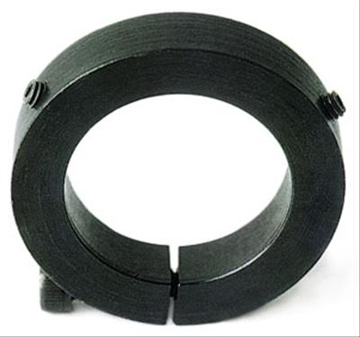
it looks like you have the wrong oil pump drive shaft, there should be about vertical .020- .050 max vertical play in the oil pump drive with the distributor clamped in the intake, it sounds like you have the slightly shorter pump drive designed to use with a BIG BLOCK pump mounted in a SBC engine, or the distributor collar prevents it seating to full depth, but what ever the cause Id suggest seeing why the distributor seems to not be seating full depth as getting it to seat a bit deeper solves both issues,modifying the distributor clamp ring might help, they also make adjustable height distributors, and replacement slip collars for this rather common issue
read this thread
viewtopic.php?f=54&t=123&p=326#p326
http://www.msdignition.com/Products/Dis ... butor.aspx
your current distributor can usually be easily modified by a local machine shop with a lathe for an adjustable slip collar by carefully machining off the current one and adding a slip collar, if you need to make distributor gear to cam gear engagement or oil pump drive shaft length changes
http://www.summitracing.com/parts/MOR-26217/?rtype=10
I removed the .065" gasket from under the distributor allowing it to drop. Then I checked the gear pattern again, it looks good now. The collar on the MSD distributor is 5/16" (.312"), so I don't see a problem with machining off .050". I shouldn't need to purchase a slip collar. After the intake gaskets compress I should be about right, if need thou I can put a shim under the distributor to raise it. Oddly enough it's the same size and the shims I need for my cranks gear.....1-1/4".
Dropping the distributor by .065" did NOT change the end play for the oil pump driveshaft. If I measure the overall length of the oil pump driveshaft I get 5.95". Whats the correct way to measure this length ??? I'm going to need something about .100" longer to make the end play about .050".
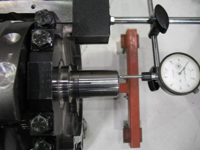
Is the depth with which the two gear mesh, did this look deep enough? I measured the backlash at .006". Is this about right or would an oversize gear help this???
I guess now would be a good time to ask if the distributor has the right gear material to go with the Billet Core camshaft?

Dropping the distributor by .065" did NOT change the end play for the oil pump driveshaft. If I measure the overall length of the oil pump driveshaft I get 5.95". Whats the correct way to measure this length ??? I'm going to need something about .100" longer to make the end play about .050".
Is the depth with which the two gear mesh, did this look deep enough? I measured the backlash at .006". Is this about right or would an oversize gear help this???
I guess now would be a good time to ask if the distributor has the right gear material to go with the Billet Core camshaft?
Last edited:
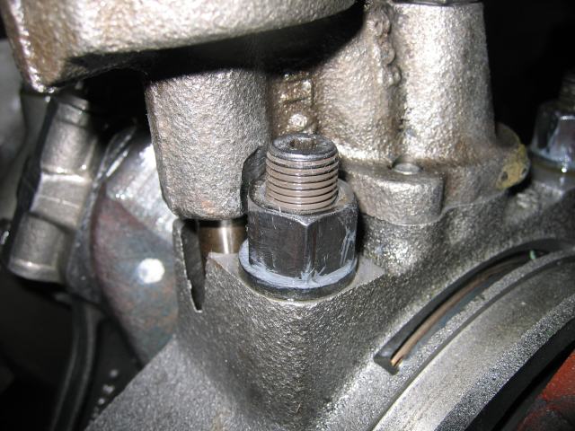
your ONLY measuring the distributor shaft movement in that picture the oil pump drive shaft slack is totally different, and can,t be measured without the oil pan off and access to the oil pump dive shaft with both the distributor and oil pump mounted
I might have a solution to my problems with the distributor gear to cam gear interface. I've tried calling MSD to verify what I'm wanting to do, but their phone system seems to be down.
There are several shims within the distributor that I could use to lower the distributor gear. My biggest question is, do I need to leave at least one steel shim (.032" & .020") under the magnetic pickup plate. If I can remove both, then I can lower the magnetic pickup and then also remove 2 - .025" shims (.050" total) from just under the reluctor. This would maintain alignment between the magnetic pickup and the reluctor.
This would certainly be much easier than machining the distributor housing.

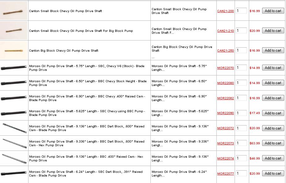
Moroso makes a 6.24" oil pump driveshaft that I could massage and make work, solving my other problem. I need something in the neighborhood of a 6.1" shaft. Grumpy explained to me how to modify this to make it work. It's a shame it has to cost $21.95, where all the other shafts are about $15.
http://www.summitracing.com/parts/MOR-22077/
Last edited:
as my dad used to say
" you can be 100% certain the company that made that distributor or other component using those spacer shims, doesn,t have a 100 acre warehouse, stacked 12 feet deep in pallets of full of extra shims they are trying to get rid of by sneaking a few extra into each distributor they sell, thinking no one will notice!"
shims in factory installed stacks ALWAYS indicate some critical clearance or spacing requirement, and are installed for some reason , the shims are there so the machined tolerance can be finely adjusted, just like on a differential where the ring gear pinion gear are set to a certain lash distance you can be sure the shims are their for a reason.
I was curious so I called MSD tech support,... no one knows everything ..... MSD Tech Line: 915-855-7123
as Ive said many times ask the manufacturers if you don,t know, THE tech guy I spoke too,said the distributor shims are there to maintain a .010-.017 vertical clearance that must be maintained to provide correct clearance on both the upper magnetic pick-up and lower cam gear to distributor housing
now Im not sure what it is and Ive always just used a slip collar and a machined oil pump drive shaft to get the correct distributor/cam gear interface or mesh pattern centered on the gears , be assured theres a reason the shims exist and are there!

keep in mind the distributor base forms one wall of the lifter gallery oil passage

so grooving the lower oil band directly above the point where the gears start to mesh helps spray extra oil on the distributor/cam gears contact area, and yes that changes with distributor position so most guys cut a small fine groove in both the lower block wall and the distributor lower section above that location to assure a constant oil mist spray into the meshing gears
" you can be 100% certain the company that made that distributor or other component using those spacer shims, doesn,t have a 100 acre warehouse, stacked 12 feet deep in pallets of full of extra shims they are trying to get rid of by sneaking a few extra into each distributor they sell, thinking no one will notice!"
shims in factory installed stacks ALWAYS indicate some critical clearance or spacing requirement, and are installed for some reason , the shims are there so the machined tolerance can be finely adjusted, just like on a differential where the ring gear pinion gear are set to a certain lash distance you can be sure the shims are their for a reason.
I was curious so I called MSD tech support,... no one knows everything ..... MSD Tech Line: 915-855-7123
as Ive said many times ask the manufacturers if you don,t know, THE tech guy I spoke too,said the distributor shims are there to maintain a .010-.017 vertical clearance that must be maintained to provide correct clearance on both the upper magnetic pick-up and lower cam gear to distributor housing
now Im not sure what it is and Ive always just used a slip collar and a machined oil pump drive shaft to get the correct distributor/cam gear interface or mesh pattern centered on the gears , be assured theres a reason the shims exist and are there!
keep in mind the distributor base forms one wall of the lifter gallery oil passage
so grooving the lower oil band directly above the point where the gears start to mesh helps spray extra oil on the distributor/cam gears contact area, and yes that changes with distributor position so most guys cut a small fine groove in both the lower block wall and the distributor lower section above that location to assure a constant oil mist spray into the meshing gears
I got thru to MSD this morning and talked with the tech there. He said I didn't need to worry about the magnetic pickup and the reluctor being in perfect alignment. In fact if there was only a 50% overlap, it would still work fine....well I will be way better than that. Just as long as a piece of metal passes by the magnet to interrupt the field. So I'm going to take out 2 of the .025" shims from under the reluctor lowering the whole shaft, including the distributor gear. Then I will need to add shim between to gear and bottom of the distributor to maintain the shaft end play.
The tech said the end play should be between .008" - .013", I have .014". So I also hope to add a .005" shim under the reluctor to reduce the end play from .014" to .009".
When I measure the shims that go next to the gear .5 x 1.0 ( ID x OD ), that is a non-standard size. Everything I found was .5" x .75", so I called MSD back again. The same tech answered and gave me part numbers for those shims, then transferred me to sales. The girl there told me the shims were 10 cents each, since I only needed a couple she is sending them to me free of charge. What she called a goodwill order.
Yea distributor problem solved without machining !!!......just need to get the oil pump driveshaft of the correct length now.

Last edited:
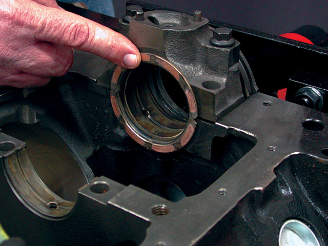
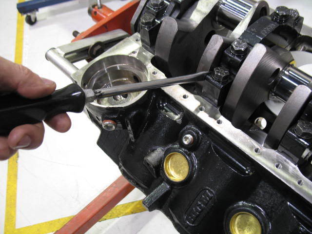
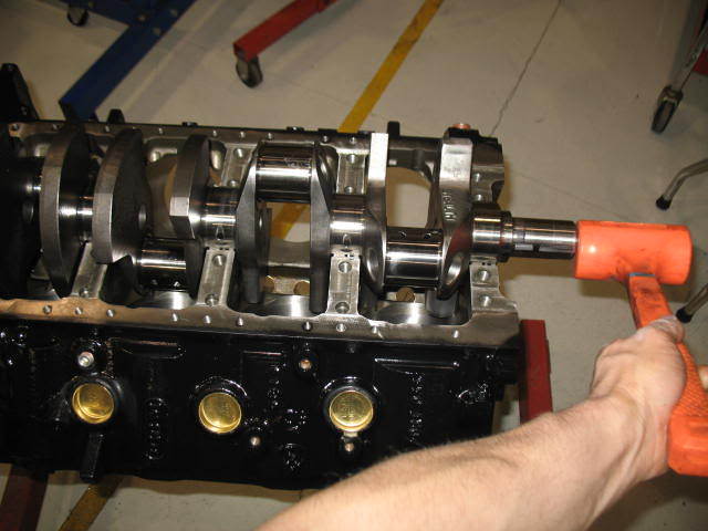
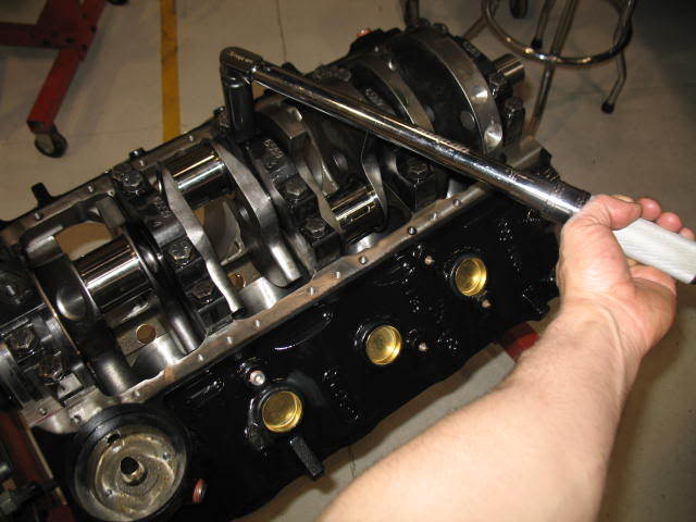
I've measured the crankshaft end play before and got .004". Yesterday I got serious about trying to increase the clearance. Below you can see how I went about removing material from the thrust face. I only made a few passes on back face of the bearing where the most force is applied, since the crank wants to move forward from the torque converter or clutch. The rest of the material was removed from the front face where it's not as critical.
Before removing ANY material I took measurements to know where I was starting from. I took 4 measurements per bearing, one for each segment. The measurements I got on the block side bearing width was 1.7174 to 1.7180" and the cap side measured 1.7175 to 1.7179".


Is it typical to have .003" to .004" MORE crankshaft end play when only one bearing is installed ???
I've measured in 4 places so I could try to be consistent when removing material across a single face of the thrust bearing. I'm wanting to stop here at .006", since this is a hand operation and I could make the bearing width variation worse.
Last edited:
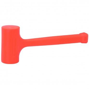
your going to be fine as it sits once you carefully clean the parts, the thrust bearing clearances will open slightly the first few hours of run time and yes it almost standard for the trust bearing clearance to be a bit tight, once installed a couple medium hard whacks with a mallet on the front and back end of the crank in rapid succession will help seat the thrust bearing clearances
viewtopic.php?f=53&t=619&p=16819&hilit=thrust+bearing#p16819
CHECKING TRUST BEARING CLEARANCE
RELATED INFO
http://www.circletrack.com/techarticles ... ewall.html
http://www.4secondsflat.com/Thrust_bear ... lures.html
http://www.chevyhiperformance.com/tech/ ... index.html
http://www.chevyhiperformance.com/tech/ ... index.html
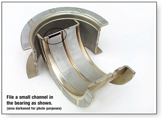
Ive done that mod for decades and I feel it helps, you onlly bevel a 45 degree edge on 1/2 the bearing mating surface like the picture shows,about 20 thousands wide just enough to provide a bit of extra oil flow, btw notice its the upper bearing shell on the pass side, front of the bearing thats beveled as thats where the bearing loads are far lower
http://www.harborfreight.com/4-lb-neon- ... 41800.html
viewtopic.php?f=53&t=619&p=16819&hilit=thrust+bearing#p16819
CHECKING TRUST BEARING CLEARANCE
RELATED INFO
http://www.circletrack.com/techarticles ... ewall.html
http://www.4secondsflat.com/Thrust_bear ... lures.html
http://www.chevyhiperformance.com/tech/ ... index.html
http://www.chevyhiperformance.com/tech/ ... index.html
Ive done that mod for decades and I feel it helps, you onlly bevel a 45 degree edge on 1/2 the bearing mating surface like the picture shows,about 20 thousands wide just enough to provide a bit of extra oil flow, btw notice its the upper bearing shell on the pass side, front of the bearing thats beveled as thats where the bearing loads are far lower
http://www.harborfreight.com/4-lb-neon- ... 41800.html
grumpyvette said:once installed a couple medium hard whacks with a mallet on the front and back end of the crank in rapid succession will help seat the thrust bearing clearances
viewtopic.php?f=53&t=619&p=16819&hilit=thrust+bearing#p16819
I went to the extra mile when tightening the rear main cap:
- Tighten until cap seats.
- Back out the bolts 1/2 turn.
- Pry up on main cap. (It has slots to get a screw driver in the side of the cap for removal. Since Dart uses a .005" press fit I used this extra step.)
- Hit the crank in front, then in the back several times.
- Seat the cap again by tightening bolts.
- Hit the crank in front, then in the back several times.
- Tighten bolts
- Take crankshaft end play measurement.
your doing great quality work, and asking all the right questions :mrgreen:
I ordered another oil pan, this time I went with the well known Milodon #30901. The Star Performance oil pan #9731 pan material is .038" thick, where the Milodon oil pan is .056" thick or another .018" thicker ( 47% thicker). This oil pan does not have a Trap Door for oil control. Price for the Moroso is $174, where the Star oil pan is $60. The trap door in the Star oil pan that I bought would not close completely, rendering it almost useless.

The Milodon approaches the problem with a different solution by making the oil travel to the rear of the pan before it can drop into the sump.

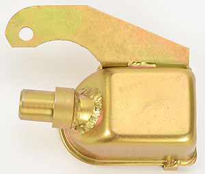
I checked the Milodon oil pan to oil pickup (Moroso 24360) clearance with my one piece FelPro gasket in place and only got 1/8" clearance. I was also kinda surprised that the pickup is as far forward as it is in the sump area.

So how do I go about adjusting this oil pickup ??? It's very well braced and I'm sure I don't want to be bending on it while it's bolted to the rear main cap. I don't see a good way to clamp it in a vise either. I don't have a acetylene torch to heat it with either.
Looks like I need a good local friend.

Last edited:
(1)
personally thats why I like having a welder and a die grinder and a MILL, while its the least likely option ,Id consider just cutting a 1/4" out of the center of that (L) bracket brace, that supports the pick-up tube and re-weld the brace after rotating the pick-up tube to get the correct pan floor to pick-up clearance and die grind the pick-up screen off the pick-up tube rotate it , verify the angle and clearance and re-weld it to keep it parallel to the oil pan floor,
(2)
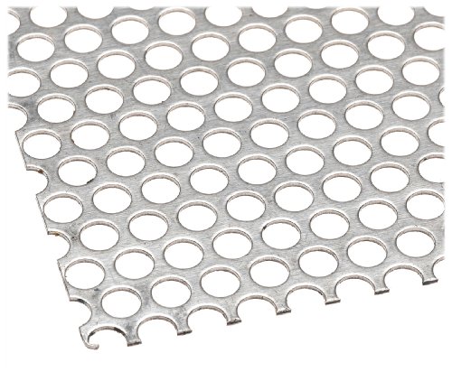
a second potentially simpler solution is just to band saw off the screen and a 1/4" of the screen housing and re-weld on a custom fit cover patch of perforated sheet steel
(3)
then theres always the third and most used option, not using that pick-up at all...,and of calling the oil pan manufacturer and asking what pick-up is designed to work with that oil pan that gives the correct clearance as theres usually several options available
grumpyvette said:(1)
personally thats why I like having a welder and a die grinder and a MILL, while its the least likely option ,Id consider just cutting a 1/4" out of the center of that (L) bracket brace, that supports the pick-up tube and re-weld the brace after rotating the pick-up tube to get the correct pan floor to pick-up clearance and die grind the pick-up screen off the pick-up tube rotate it , verify the angle and clearance and re-weld it to keep it parallel to the oil pan floor,
(2)
a second potentially simpler solution is just to band saw off the screen and a 1/4" of the screen housing and re-weld on a custom fit cover patch of perforated sheet steel
(3)
then theres always the third and most used option, not using that pick-up at all...,and of calling the oil pan manufacturer and asking what pick-up is designed to work with that oil pan that gives the correct clearance as theres usually several options available
I think the problem I'm having is the Melling 10552 Oil Pump. With it's 10% over volume, the gears are only .112" longer. All the pickups seem to be for a stock or 25% over volume pumps. The Moroso 24360 pickup is for an 8.25" pan, just like the Milodon # 18214. Both have the 3/4" diameter pickup tube.
The pickup tube is only 1/8" from the screen, so cutting a 1/4" off the pickup housing doesn't seem to be an option either, in this situation.
Option 1 looks to be the only option of course, the one that involves the most work. But that's to be expected when building High Performance engines.


Last edited:
Im always amazed at the quality and clarity of your posted photos
viewtopic.php?f=54&t=1800&p=16261&hilit=shrapnel#p16261
MILODON, MOROSO and MELLING just to name a few sources have several dozen oil pump pick-up designs, if your not into fabricating custom parts
fabricating something custom or modifying something you currently have by cutting, measuring and re welding should not be very dificult

http://www.jegs.com/i/Milodon/697/18315 ... tId=750962
http://www.moroso.com/catalog/categoryd ... code=12001
http://www.milodon.com/oil-system/pickups.asp
http://www.jegs.com/p/Milodon/Milodon-O ... c1|0&Nty=0
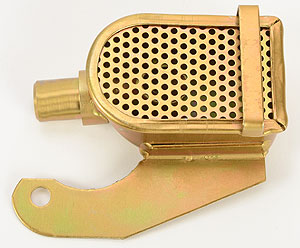
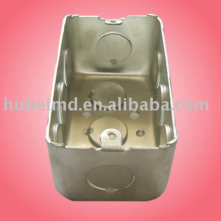
BTW you won,t be the first guy to use an electrical outlet box and some perforated sheet steel, and a welder to build a custom oil pump pick-up with a brace to the oil pump
viewtopic.php?f=54&t=1800&p=16261&hilit=shrapnel#p16261
MILODON, MOROSO and MELLING just to name a few sources have several dozen oil pump pick-up designs, if your not into fabricating custom parts
fabricating something custom or modifying something you currently have by cutting, measuring and re welding should not be very dificult
http://www.jegs.com/i/Milodon/697/18315 ... tId=750962
http://www.moroso.com/catalog/categoryd ... code=12001
http://www.milodon.com/oil-system/pickups.asp
http://www.jegs.com/p/Milodon/Milodon-O ... c1|0&Nty=0
BTW you won,t be the first guy to use an electrical outlet box and some perforated sheet steel, and a welder to build a custom oil pump pick-up with a brace to the oil pump
I wanted to take some measurements before I cut the weld so I could remove the 3/4" tube from the pickup assembly. So when I got two different measurements I wondered how that could be. When I bolted everything together I had 1/8" clearance to the oil pan on all four corners of the pickup.

I discovered that the oil pump in not parallel with the oil pan rails, but WHY ??? Next I looked at the distributor mounting pad on the intake manifold, sure enough it's not parallel either. Not once have I read about this anywhere.


It would appear that the distributor mounting pad and the oil pump are parallel with each other so the oil pump driveshaft line-up.
I finally got the two components cut apart.

Last edited:
I cut a 1/4" out of the brace for the oil pickup. Set the oil pan on some paint sticks that are the same thickness as my pan gasket. Since the oil pan material is about 1/16" thick, then with the 1/2" dowel rod there should be 7/16" clearance when I'm done.

When I was happy with everything, then I tack welded the brace where it over laps.

Then I went back and checked the actual clearance with modeling clay and my real pan gasket in place. In the end I ended up with 1/2" clearance at the back edge and an additional .030" on the leading edges.

Last edited:
looks like your doing a fine job, few people even bother to verify those clearances thats, one major reason why its so darn common to have guys with lubrication issues they can,t explain.
btw BRAZING is far easier than WELDING when your dealing with trying to stick two dis-similar materials like mild steel oil pump pick-up tubing to a cast steel pump housing
btw BRAZING is far easier than WELDING when your dealing with trying to stick two dis-similar materials like mild steel oil pump pick-up tubing to a cast steel pump housing