TBucket Engine Project (Dart SHP)


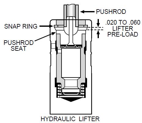
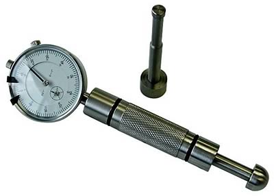
I went back to check the Piston-To-Valve clearance again using the clay method. This time with the dial indicator on the spring retainer so I could see if the valve moved, I adjusted the poly lock until the lifter stopped compressing and the valve retainer started to move. Then I backed up until the indicator read zero again. With this method I got roughly .530" lift out of the theoretical of .562/.567". I then turned the engine over 10 revolutions.

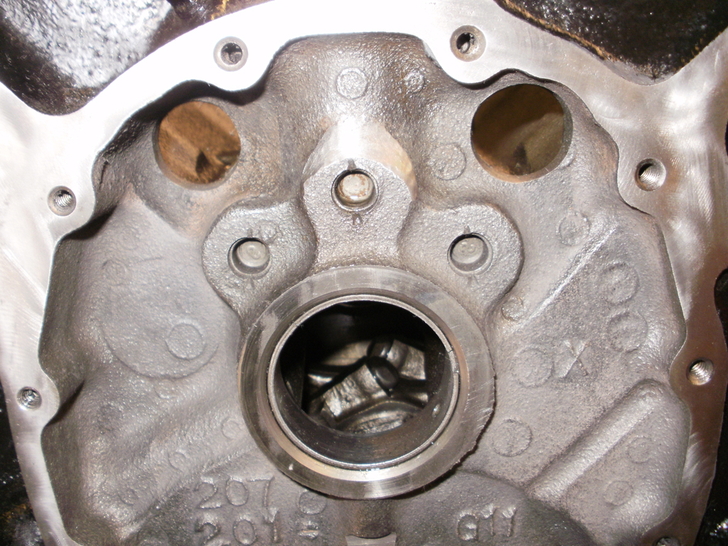
As you can see from the picture the valve is hardly even making an impression in the clay.

ValveToPiston_Clay1594.jpg
ValveToPiston_Clay1592.jpg


I also wanted to see how this compared to the other method that I tried earlier (Posted: Mon Dec 12, 2011 11:14 am). The clay method show that I have considerably more clearance than the other method. Since the valves and pistons don't move parallel to each other, the the actual clearance will be something greater than the measured value.

ValveToPiston_DialIndicatorMethod01.JPG


All checks were performed with the adjustable pushrod set to 7.45".

 
Last edited:
Like I stated earlier your doing everything correctly, your checking and testing correctly, but you seem to have difficulty believing your doing excellent work?
a great deal of the doubt as to the true effective lift and clearances can be checked with the correct replacement checking lifter tool, used in place of a hydraulic lifter
hylifters.jpg

pro-66838_w.jpg

116_0701_04_z+valve_to_piston_clearnace+measure.jpg

yes I know theres a STRONG tendency to suspect your screwing it up the first few times, you do it but in this case its not true, if everyone took the time and effort you have there would be darn few guys with busted engines
if your getting .530 measured valve lift at the valve and the cams been indexed correctly then you,ve obviously got much more than the .100-.120" minimum valve to piston clearance required even if you have .570 lift, so if you want to recheck theres nothing preventing you from slipping a .040 feeler gauge between the valve stem tip and the rocker tip and getting the full .470 lift your expecting with the lifter seat extended to the max, keep in mind that the true valve lift changes slightly with rpms and oil pressure as the lifter seat pumps up and bleed off rates are reduced as rpms increase but your testing indicates your hardly near critical clearances , you could also retard the cam timing a couple degrees if you choose to to increase the intake valve to piston clearance a bit more if you choose too,retarding the cam lets say 3-to4 degrees will move the whole torque curve about 200rpm higher and tend to increase peak hp and kill a bit of low rpm torque and reduce the engines potential to get into detonation with crappy gas, so its a valid choice.
 
Its normal the lifter compress and you have the same result with a mechanical lifter, if i get it correctly..
If you used a mechanical lifter youd probably set some clearance with a feeler gauge(probably between 0.010-0.030", i didnt work with mechanical much yet but that seem a good average setting), that is also a reduction in lift of about 0.010-0.030 just like the ammount your hydraulic lifter are compressing. don't know if that make sense.

From my experience, the lifter need to decompress or in the case of a mechanical have some clearance so the lifter can spin in the bore for a flat tappet cam, and probably because you dont want the valve train too tight at 0.000" clearance. Now tell me if i am right or wrong.

Pre-loading the valve just make them harder to compress, it wont stop them from compressing.. but it help when setting valve lash because you can feel where is zero lash more easily this way. At least that was my experience.

For setting the cam timing.. its best to use a mechanical lifter or the tool that Grumpy posted above. For my cam timing i also used the side of the hydraulic lifter just like you with success, its just more hassle doing it this way.

My cam is 4° advanced from the factory, removed 2° from that, again its a good thing as grumpy just said above :p.
 
I am questionning about the lifter pump-up on Grumpy's post above­
Dont lifter pump-up only when you are exceeding too much the RPM range for the hydraulic lifter, wich is best to avoid?, too high rpm with a heavy valve train/too light spring can also get the engine into valve float? wich is not good on a S/C engine.
 
mathd said:
From my experience, the lifter need to decompress or in the case of a mechanical have some clearance so the lifter can spin in the bore for a flat tappet cam, and probably because you dont want the valve train too tight at 0.000" clearance. Now tell me if i am right or wrong.
A hydraulic lifter would not decompress to the point where there is clearance in the valve train. Not if its adjusted properly. Oil pressure keeps any clearances from developing, but it's NOT going to stop the hydraulic flat lifter from rotating properly.


Indycars said:
mathd said:
From my experience, the lifter need to decompress or in the case of a mechanical have some clearance so the lifter can spin in the bore for a flat tappet cam, and probably because you dont want the valve train too tight at 0.000" clearance. Now tell me if i am right or wrong.
A hydraulic lifter would not decompress to the point where there is clearance in the valve train. Not if its adjusted properly. Oil pressure keeps any clearances from developing, but it's NOT going to stop the hydraulic flat lifter from rotating properly.


Thats what i am saying,
The hydraulic lifter will compress, not devlopp a clearance since there is some preload on the lifter seat.
But for mechanical flat tappet i read you want 0.010" to 0.030" clearance/valve lash that to me has the same effect as the lifter compressing about the same ammount.
If you use a 0.010" to 0.030" tappet gauge am almost sure your hydraulic lifter will compress / bottom out about there when on the 0.00" lift portion of the cam lobe..

But yeah, as RPM increase the lifter no longer get compressed? thats the part i dont get.
If thats the case its best to use a feeler gauge to check the PTVC as Grumpyvette said so you can be sure of the true max PTVC.

EDIT:
ohh, its fine, after some re-reading and thinking i finally got it lol.
 

Here is one pre-assembly check I didn't have on my list. I was putting the lifters back in their box, when I noticed this paper again. This time I decided to read it and thought I had better check the statement in the red box.

You can find my check list here: viewtopic.php?f=99&t=4894
CrowerLifterInstructions1600.JPG

I used my caliper to measure the depth of the lifter bore down to the Oil Galley. I did this by looking thru the oil galley and extending the depth rod until I could just barely see it. I also set the lifter in it's bore and lightly scribed a line at the top of the lifter bore, you can see it in the last picture below.


LiftBoreToOilGalleyDepth1604.jpg

Here are the measurements I came up with, looks like I should be Ok with .070" clearance ( .990 - .920 = .070"). I also placed a lifter in it's bore, such that it contacted the cam base circle and looked thru the oil galley. When the lifter is on the base circle, it's most likely to have a problem.


LifterDimensionsInOilGalley1595.jpg

Looking at the lifter oil feed hole, seems the oil has a direct path to the hole, even when it's not too low.

So why does it matter if it goes low enough that it drops into the oil galley ???


Last edited:
I guess the oil feel hole is covered by the lifter bore creating some restriction, now if this hole is in direct path to the oil gallery this may cause too much oil to get on top of the engine(heads) by this/or the lifters.
Uncovered oil feed hole/in direct contact with oil gallery = too much oil being pushed into the lifter/top of the engine.
 
I just remembered that a hydraulic lifter has a oil metering disc, which should restrict the flow of oil to the top end. So I don't see why it matters at all now. Unless my lifters are made differently.

HydraulicLifterExplodedView.jpg
 
Last edited:
Ive never measured a hydraulic roller lifter and block that failed to let the oil feed hole in the lifter not feed oil pressure to the lifter feed hole,or to not drop low enough to allow the lifter oil feed hole to enter the top of the oil passage when the lifter was on the cams base circle,

baselobeda.jpg
they all are designed to feed oil into the lifter on the cams base circle and many constantly have oil pressure feed to the oil hole in the lifter.
look many have feed holes like this that constantly feed oil because the feeds a vertical notch

hlf1.jpg


file.php

look very closely at your lifters theres a small recessed notch that allows oil to flow between the lifter outer diam. and lifter bore wall up from the lifter gallery oil passage at almost all times to keep pressurized oil from the lifter oil passage feeding up to the lifter
 
I have my test sample for the engine paint from Por15. They don't recommend using the high build primer called "Tie Coat Primer" for engines. In fact in an email the guy at Por15 suggested using the Engine Enamel first, then Tie Coat Primer if I had to use a primer. So I prepared a test sample with a couple of different steps.

I'm wondering what would be the maximum temperature that I should expect on the block surface ??? I want to put the test sample in a oven for 24-36 hours to see which one looks better. Or maybe there will be no difference.

EnginePaintTestSample1621.jpg


There is a definite down side to the Por15 Engine Enamel for most people, it needs to dry for 6-8 days before starting the engine.


Last edited:
I doubt youll see engine block temps exceeding about 350F and keep in mind that coolant rarely exceeds 270F and oil rarely exceeds 300F even in extreme conditions when things are not working as designed BUT exhaust manifold temps commonly exceed 550F-850F and in many cases the exhaust manifolds, or headers are located very close to the heads and block in some header and manifold designs, so reflected heat is significantly higher than you might imagine near the headers

irtemp.jpg

http://www.professionalequipment.com/ex ... ermometer/


headerclear.jpg


redheaders.jpg


stc1.jpg

stc2.jpg
 

To check the rod bearing clearances with Plastigage:

- I needed to make sure the crankshaft did NOT rotate with Plastigage in the rod, so I removed the bearing from the rear main cap and put a piece of rubber fuel line under the main cap.


PlastigageLockCrankshaft1623.jpg

- Then I tightened the rear main cap until the crankshaft was difficult to move.

- I put a smear of Vaseline in the upper half of the rod, then placed a piece of Plastigage in the Vaseline. The Vaseline prevented the Plastigage from moving during the installation of the Piston & Rod assembly.


Plastigage&Vasoline1608.jpg

- To get an accurate measurement with Plastigage, I used two feeler gauges between the two rods to keep them from twisting on the journal and skewing the measurement.


RodBearingClrCheckingProcedure1647.jpg

- The rods were torqued in three steps, 25, 45 and 64 lb*ft.

- Loosen the rods bolts with feeler gauges still in place

- Compare Plastigage to the scale provided on package.


Plastigage.002_Inches_1614.jpg

The results are below in my Excel Table

RodClearanceExcelTable.JPG

 
Last edited:
The most variation was approximately .0015", when checking any pair rods for side clearance in 4 different positions.

I'm trying to check the rod to camshaft clearance. Is there certain cylinders that come the closest ???

It's really tough trying to see in midst of all those moving components while trying to see on the other side rod journal. I'm using a telescoping mirror, but that's not a perfect solution either. Any suggestions!
 
lobeclear.jpg

this is what Ive seen posted frequently
BaseCircleDia.jpg


block-clearance.jpg

why you need to verify the cam to rod bolt clearance

rod-grinding.jpe

on some stroker applications SOME rods need to have the bolts ground for cam lobe clearance

Ive seen , cylinders number 1,2,5,6 as the most common for contacting cam lobes, posted frequently, but Ive always just checked each rod separately without the rings installed as I test fit the components, Ive usually used a semi straitened, extra large paper clip that measures about .055 as a feeler gauge in the past but currently use a extra long cable tie as its far less likely to scratch a cam lobe and its flexible and easy to use and if it gets pinched between the two theres no potential damage done and, working with only a single connecting rod in place while checking, a really strong light, and a mechanics mirror helps, so I could see half way decent

31P02nf2p2L.jpg

image_16331.jpg

one of those LED flash lights helps to get light into some areas
image_16738.jpg
 

I tried using the zip ties but I couldn't be sure, without a doubt, they were between the cam lobe and rod since I can't see it. I can see all around it but just can't see directly the cam lobe and rod when they pass each other with the zip tie there.

So I used some 12 ga solid wire, which is .140" diameter at the insulation and .080" diameter for the copper conductor. With this in there I still couldn't see directly, but I could feel the rod squeeze the the insulation.....then I knew for sure I had at least .080" of clearance. It was also easier to shape it and it held, where the zip tie would spring back.

CamToRodClearance1649.jpg
CamToRodClearance1650.JPG


So I never had less than .080" clearance, between the any cam lobe and the adjacent rod.


Last edited:
as always , darn impressive photography, and the wire idea is really good!

Ive got to try that.... and yes anything over 0.055 is fine for clearance, I generally check each cam lobe to connecting rod clearance one at a time , working with only a single connecting rod in place while checking, a really strong light, and a mechanics mirror helps, so I could see half way decent, (each numbered and used in its indicated cylinder) in place, temporarily in the engine, it makes seeing what your doing far easier

a really strong light, and a mechanics mirror helps, so I could see half way decent [/color]

31P02nf2p2L.jpg


one of those LED flash lights helps to get light into some areas
image_16738.jpg
 
I did try using the mirror, in fact I had two with different size mirrors. But even with an LED pen light I just couldn't be sure that I was looking straight thru the clearance and then trying to judge the distance I was seeing left alot of doubt in my mind.

With the wire it wasn't very hard to hold it laying on the lobe with one hand and rotate the crank with the other hand. You knew for sure the wire had not slide to the side as the rod went by, because you could feel the increase resistance to turning the crank as it squeezed the insulation. Also it was fairly easy to do with all 8 rods installed. I was done in 30 minutes.

I got lucky in that the 12 ga wire was exactly what I needed, but you could have several sizes on hand when you get ready to start checking.
 
Back
Top