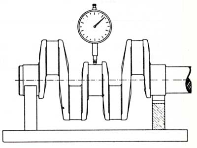
I've done some more clearance checking for the crankshaft. The run-out looks to be normal except the #4 main
has considerably more than the others.
the first thing Id do is call the crank manufacturer and get their input, what your describing is not un-common and if you have all the other run-out specs that close , while far from ideal its not likely to be something the local crank shop can,t polish out to a closer spec.
if you want to get it correct (ideal route) or you could run it with a .003 bearing clearance and most likely get by with it (not ideal)
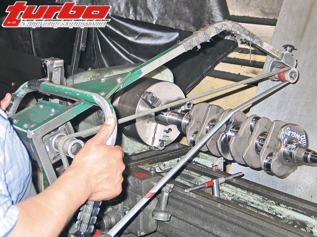
the OLD SCHOOL CURE involved marking the high side of the man journal and using a stiff leather belt about 2" wide and some 2.5" wide1000 grit emery cloth under the belt and to do a shoe shine polish on the high side of the journal followed by careful RE-measurement every few minutes and a good cleaning
looking at a Chevrolet factory shop manual and its spec on this .0002 on a new shaft and .001 for a serviceable shaft in "V" blocks.
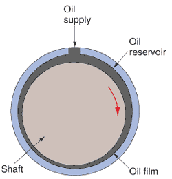
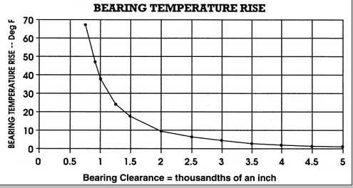
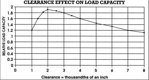
bearings them self DON,T support the crank,on their surface,with the engine running ,its the PRESSURIZED FLOW OF OIL between the crank and the bearing thats supposed to support the crank in a running engine.
so the clearances are obviously not consistent ,a bit of 1000-1200 grit emery cloth work and a good cleaning might help, but Id get the crank manufactures input and personally Id take it to a local crank shop for a quick polish after discussing my concerns with the machinist
Rick Says:
Should there be any grinding or polishing on a crankshaft that has been NITRIDE HARDENED, unless you are prepared to go
thru the process again ???
The crankshaft end play is on the low side
its common for the thrust bearing to need to be seated,on that 4th main saddle, Id suggest oiling the bearings and crank with assembly lube, installing it with all the main paps in place but only tightened to about 30 ft lbs, and Id give both ends of the crank while youve got it sitting in the main bearings with the main caps loosely tightened a couple good whacks with a lead hammer directly in line with the main axis, driving in forward and backward in the main saddles a few times then RE-measure end play.
Rick Says:
I did seat the bearing with a small dead blow hammer, but only from the rear. I did not do both ends.


")