Porting School #6 - Secrets to reduce valve shrouding
#6 Port Appraisal and Valve Shrouding
In part #5 we identified a primary flow restriction- now is time to get into more detail.
By
David Vizard
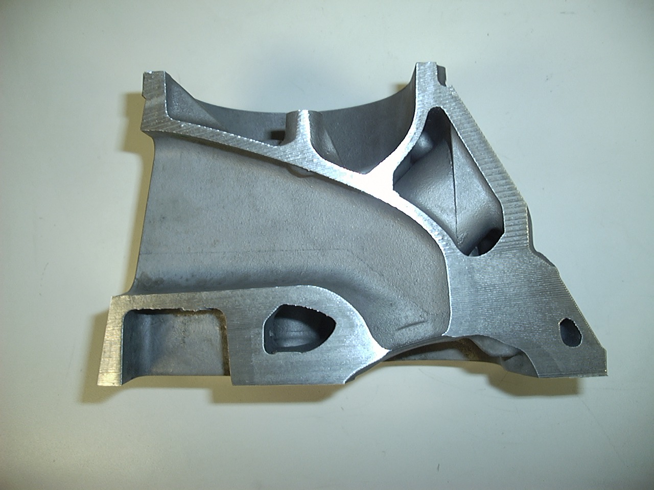
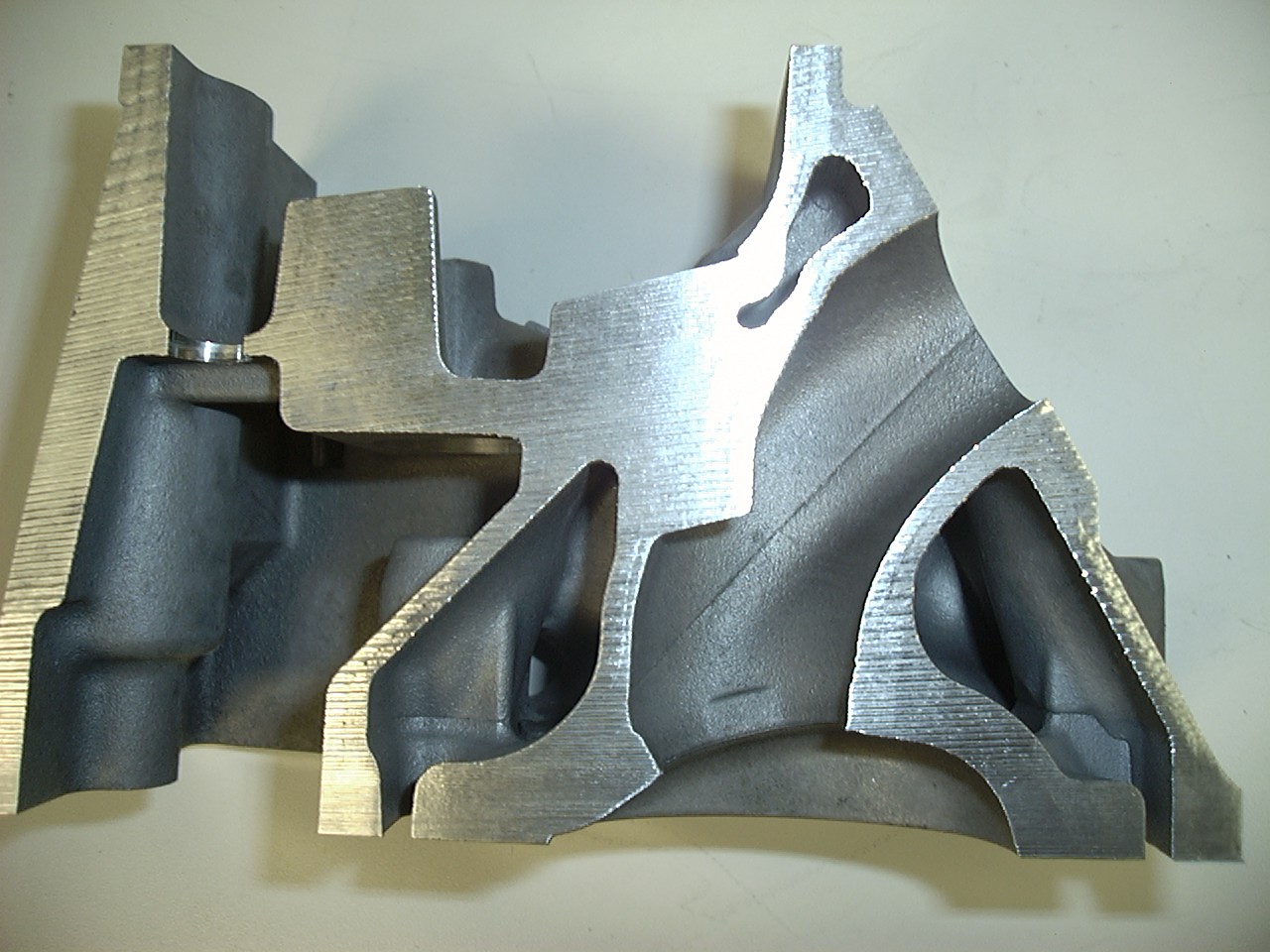
Porting School #5 established that the valve and valve seat is a prime restriction point - now let us take a closer look at what we are dealing with here. In part #5 I dissected the port to make a point. I believe the point that the valve seat, not the port itself, caused potentially the biggest restriction to flow’ was satisfactorily demonstrated. However much that analogy may simplify things, it does in fact contradict one fundamental truth about engines in general and cylinder heads in particular. That fundamental truth is that in the process of developing a high performance engine almost no part of it can be considered in isolation. Although (in terms of air flow) the interdependence of one section of the head on another in the drawing below varies we cannot take any one part of it and truly consider it in isolation.
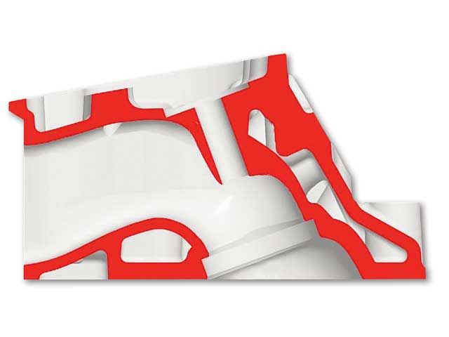
This section was shown in Porting School #5 but I want to bring your attention back to it here. What we are going to do is both progressively put the head back together and lift the valve further.
But before we consider the implications here let us establish a couple of geometric factors concerning a valve and the hole it occupies. To make life easier check out the drawing below.
What you see in the above drawing is a valve lifted to the point where the open curtain area surrounding the valve is equal to the valve diameter. What this means is that if the valve seat was zero width, opening the valve any further than 0.25 of it’s diameter will not present any more breathing area to the cylinder. However because the seat occupies space under the valve we find in practice that the curtain area reaches the effective area under the seat and minus the valve stem at about 22.5% of the valve diameter. So for our example 2 inch valve lifting it more than 0.45 inches won’t actually deliver any more breathing area.
So does this mean that valve lifts above .225 D are a waste of time as they won’t deliver any more flow? No – because of losses and the areas surrounding the valve, lift values, especially for a parallel valve engine, can show increasing flow up to as much as 0.35 D. Although the 0.35 D may well represent a limit some special things start to happen at about the 0.25 D – especially in a typical two valve design of cylinder head so remember that relationship for later.
Re-assembling the Port.
OK now we have that bit of nomenclature concerning the lift to diameter ratio covered let’s go back and look at section ‘C’ of the above cylinder head. If we consider this section in isolation and the valve lifted to say 0.35 D or more we will find that, because of the uninterrupted straight approach, this section will flow a lot of air. In the case of our model, that’s about 275 cfm. However if we add section ‘B’ to ‘C’ then things change dramatically. The air now has to make a turning approach to the valve seat area.
Look at the throat section on the left. If we take the valve and lift it from about a mid lift point to something equal to say 35% of it’s diameter (0.35D) we can expect a big increase in flow. If the valve is lifted even further to say 100% of it’s diameter it has become sufficiently far removed from the seat to be about out of the sphere of influence of the seat. But this situation makes some assumptions. The first is that the air approaches the back of the valve from a near optimal direction and secondly that there are no further impediments to flow once the air has passed the seat. Unfortunately these circumstances might not represent the real world. If we re-assemble our sectioned port with the part that houses the guide we find that the air is now constrained to approach the seat area in an arc. At higher lift figures the air on the floor of the port, that’s the short side turn, is going too fast top make it around the turn. This results in skipping across the back of the valve and attempting to go out on the top (the long side) side of the port. This means the short side and the valve circumference in the immediate area is under-utilized. But our problems don’t stop there. Check out the red arrow labeled ‘Problem!’ This situation is called valve shrouding. Only by lifting the valve to extreme lift values can the head shown here avoid the restriction cause by this shrouding. For a clearer picture of what valve shrouding is check out the next drawing.
With the arcing approach to the back of the valve the flow situation changes dramatically. Now we are into port design rather than seat design. Although we can never truly separate these two aspects of the induction tract our focus will turn more toward the optimization of the shape of the port. But the approach to the back of the valve is not our only concern if we are dealing with a 2 valve per cylinder, parallel valve head, having either a bath tub or wedge chamber shape. We also have to deal with valve shrouding. Instead of using 1000 words here I am going to refer you to the drawing below and limit my words to 900 or so!
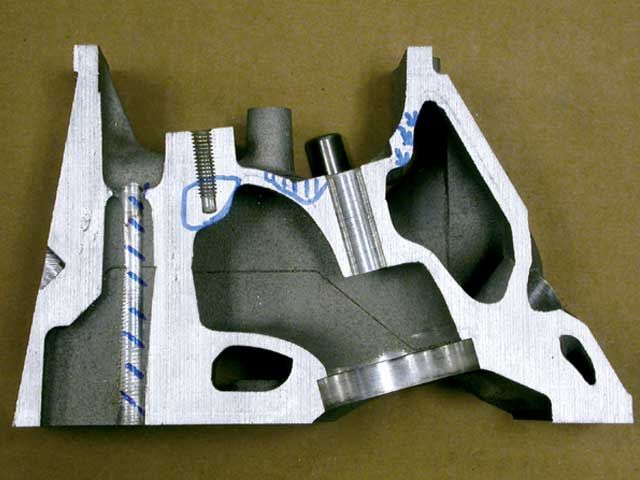
Imagine that for some reason you have a valve, seat and port at the bottom of a cylinder as shown in the left hand drawing. Because the walls of the cylinder are snug to the circumference of the valve it matters little how high the valve is lifted as no air will flow around the edge no matter what. Now let’s pull one side of the cylinder wall away from the valves circumference as per the drawing on the right. With the wall this far from the edge of the valve there is a clear path for the air to flow around that side of the valve.
From the preceding drawing it can be seen that if either the combustion chamber or the cylinder wall is too close to the edge of the valve flow will be impeded – and all this brings us to the $64,000 question - how close is too close??? If you supposed that there might not be a simple answer to this question go to the top of the class. There are two ways we can consider shrouding of a valve. The first is just by consideration of the through-flow areas involved as the air attempts to navigate it’s way around the valve. The second is shrouding relief that is dictated solely by the degree to which that part of the valve is utilized due to the amount of air flow at that part of the circumference. That may sound a mouthful but I will expand on that in a moment. For now let’s consider the first situation – the through-flow area’s.
Understand that the design of the ports and chambers of a cylinder head for optimal flow/performance does not lend itself to overly simple mathematics. However a little relatively simple math applied here and we can come up with dimensions that, for want of a better description, produce a shrouding factor that is geometrically minimized. When applied to the fullest extent it produces a design that cannot be geometrically de-shrouded any further without mechanical compromise to the system. An example here is valve shrouding caused by the cylinder bore. If this is cut away then the valve may be un-shrouded further but the rings won’t seal up! What follows is an example of a real world situation.
What you see here, drawn to scale, is a typical head design for a small block Chevy. It is of a wedge configuration with the deep side on the plug side of the chamber. For the valves to be fully geometrically un-shrouded at 0.25D lift there must be a completely clear area from the edge of the valve right out to the black circle surrounding each valve. Anything within that circle is, to some degree, reducing the area of the flow path around the valve. The chamber shown is a stock Chevy design as per a 186, 049 etc high perf casting of the late 60’s through to about the mid 70’s. This chamber design was, for the most part, the starting point for just about every after market small block Chevy high performance head. In this drawing you can see that any part of the chamber colored green is, at 0.25 D, shrouding the valve. Assuming the casting thickness is there these area’s can be cut away. The shrouding caused by the bore is something we are stuck with when using this style of head with parallel valves.
To understand the next part of our discussion you need to appreciate that air does not flow in a neat and orderly fashion within the port. This is so far removed from reality and the only way you will really appreciate how far out that may be is to spend time on a flow bench and see for yourself. The drawing below shows how the bulk of the air enters the cylinder on a small block Chevy head.
When the valve is lifted to about the 0.450-0.500 range the air, although with streamlines far less tidy than shown here, enters the cylinder about like this. The bulk of the air passes out of the port and into the cylinder through the half of the valve labeled ‘A’.
Zeroing Out Geometric Shrouding.
When addressing valve shrouding with the intent of minimizing it we need to make a start somewhere and ascertaining what the form of a chamber may be, if it was geometrically un-shrouded, is as good a place to start as any.
The breathing area presented to the chamber by a valve moving through it’s lift envelop is not quite as simple a geometry problem as it may first appear. The reality is that as the valve lifts it moves through three distinct regimes, each of which requires it’s own particular set of math formulas to produce an answer as to what the through-flow area is. We are not going to deal with this now as it is more advanced stuff. However, even if we ignore that we can still come up with a very good approximation of what it takes in the way of chamber form to produce a geometrically un-shrouded chamber. What we find is that at low lift the angle of the chamber wall as it leaves the valve seat needs to be very close to 45 degrees and as the lift progresses up to the critical 0.25 D lift point the angle needs to increase to about 52 degrees from horizontal.
The drawing below gives us a good guide to the form that needs to exist around a valve as it progresses through it’s lift envelope to ensure that the flow area around it is at least equal to the effective curtain area beneath the valve head.
Look closely at this drawing. The green line represents the angle of the chamber wall as it comes off the seat. For all practical purposes this is right around 45 degrees. As the valve lift progress the point of zero shrouding of the edge of the valve in relation to the chamber wall gets slightly steeper until at 0.25D the wall angle is close to 38 degrees off the vertical (52 from horizontal)as represented by the blue line. Although not totally accurate we can say, within close limits, that when the valve is at 0.25D lift the gap between it and any possible obstruction should be equal to a minimum of 0.20D. Above 0.25 D valve lift the chamber wall can be vertical for zero geometric shrouding as the valve has reached the limit of the area it will present to the cylinder.
Minimizing Real World Shrouding.
It is entirely possible to eliminate valve shrouding at the design stage of a cylinder head. The classic Hemi layout shown above does just that. But such a design is not always practical for reasons of cost or vehicle installation. The hemi head design configuration and to a lesser extent a four valve per cylinder type head have minimal to zero valve shrouding. The drawing below shows why.
As I have previously pointed out minimizing geometric valve shrouding is only a starting point. For us to apply whatever it may show us we need to ask ourselves two questions. The first is: do we want or need to have an obstruction to flow that is at least as un-streamlined as a valve seat. In other words do we want to present the air with a second bottle neck about equal in flow capability to the gap between the seat on the valve and it’s counterpart in the head. Secondly we must ask if the part of the valve we are considering the shrouding factor of is over or under utilized as far as the airflow is concerned. Here I refer you back to the drawing showing that on a small block Chevy (and the same will apply to any head of similar configuration) most of the air goes out the long side of the port. From this it is obvious that we will want to unshroud this side of the valve more than the other for optimal flow.
If we look at what we have learned so far and apply it to a real world cylinder head we can begin to see some porting development value of drawing a zero shrouding circle around both the intake and exhaust valves. The illustration below does just that – study it and read and absorb the caption .
Take a look at the blue circle first and note it’s relationship with the cylinder bore and the combustion chamber. The most noticeable aspect here is that at 0.25D lift there is a substantial amount of valve shrouding caused by the bore as represented by the area of the blue circle overlapping the cylinder bore circle. There is little, in a parallel valve design of head, that can be done about this although it’s negative impact can be partially offset by utilizing a very high valve lift. The second point of note is that the chamber wall on the plug side has been cut away far more than whatever amount it would need for zero geometric shrouding. The reason for that is because this side of the valve is a high flow area and is utilized far more than the side opposite.
Turning our attention to the exhaust valve we can see that at the critical 0.25D lift value there is virtually no shrouding of the exhaust valve. The spark plug side of the chamber is cut away far more than is needed just to achieve zero geometric shrouding. Why is this? Here we see the chamber form having to satisfy the needs of the combustion process so the shrouding, since it is none existent in that area, becomes academic.
However there is one aspect that does show up here that had we not drawn the zero shrouding circles around the valves would have been much harder to appreciate. With any cylinder head the most important valve is the intake as (in the simplest of terms) it is a lot harder to suck a full charge in than to blow or push one out. What we see here is an intake with appreciable shrouding and an exhaust with virtually zero shrouding. This immediately tells us that both the intake and exhaust valves should be re-positioned so that the intake valve moves away form the bore wall and the exhaust towards the bore wall on it’s side of the cylinder.
So why did this head manufacture miss the mark on the relative position of the valve centers in relation to the bore? Well really they did not. The intent with this head was that it would use the same valve centers as a production small block Chevy so that it would fit all the piston valve notches as used for off-the-shelf pistons and things such as pushrod guide plate centers would remain stock. In other words everything that fit a stock head would also fit this one.
Conclusions:
I will guarantee that this is a more comprehensive lesson on valve shrouding than you could have got any where else – but are we finished on this subject yet? No – and rest assured the next level will be more advanced and reveal factors little appreciated by even most pro head porters. For now let’s consider how we can apply what we have learned so far to the development of a parallel 2 valve style cylinder head. Here’s the scenario: you have your flow bench set-up and have flow tested the head and are now amazed at how bad it is (makes you wonder what these factory engineers did with their benches eh?). What now? Take a look at the head and as far as possible identify what are likely to be the ‘busy’ areas around the valves. Next, using a valve with a center-pop in the middle scribe out, with a set of dividers, a circle around each valve that is 0.2 D out from the edge of the valve. (that’s a diameter equal to 1.4 times the valve diameter). The line you are left with across the head face is a good starting point for de-shrouding the valve.
Below is an example I worked on an 850 BL ‘A’ series engine back in the 70’s to demonstrate this point. The flow numbers show the effect of de-shrouding and how eventually a limit is reached.
The valve head in this example is 1.093 inches diameter. The green circle in the drawing represents the radius around the valve with the head in stock form. This is approximately 0.68 inches. The black curve in the graph is the flow delivered with the stock chamber form (shown by the black line in the drawing). The blue line is, at 0.80 radius, near the zero shrouding limit. When the valve was de-shrouded to this line the flow increased as per the blue line on the graph. As you can see there was a substantial increase in flow. Increasing the de-shrouding from 0.2 D to 0.3D as per the purple line increased flow further but going out to 0.4D netted only minor gains at high lift values. Remember – this is a small valve and 0.400 represents a lift to diameter ratio of 0.366. On a small block Chevy that would be equivalent to 0.740 lift.
The ‘busy’ area for this port is the lower side (port approaches from the top) of the chamber in this drawing. This particular head responds to de-shrouding because there is a reasonable straight run of port prior to the valve so and this, in conjunction with a small valve allows the short side turn to wok relatively well.
Ok – we have made a start on our investigation on ports and valve shrouding but, as important as this may be what we have so far considered is but a tip of the iceberg. Not only must we look at the ports in terms of shape but also size. All too often the Stroker McGurk syndrome eeks its way into the racers mentality. Although a big port may look like the way to go and may indeed net more flow than a smaller one it is, more often than not, a case of ‘if some is good more must be better and to much just right’ thinking. Well the news here is that it just doesn’t work that way. In our next Porting School feature we will look at tests of four different size intake ports on a 383 small block Chevy – after you have seen the dyno tests you may well have a little more regard for the port volume (size) why it is rated that way for a typical US V8 and what you may want to choose for your next build.
David Vizard