while its not IDEAL, from a pragmatic view point if you set all the main bearing clearances to spec.
on the loose end of factory specs Main bearings 0.002 - 0.003" for most engines,on small blocks, in that .025-.027 range
The machine shop said I have 0.002" to 0.0022".
I doubt youll have any issues at all, now obviously you could call the guys you had polish the crank journal and get their input,
but having seen how much clearances vary and still having seen engines run long healthy lives built with those tolerances in
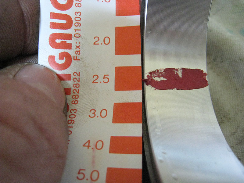
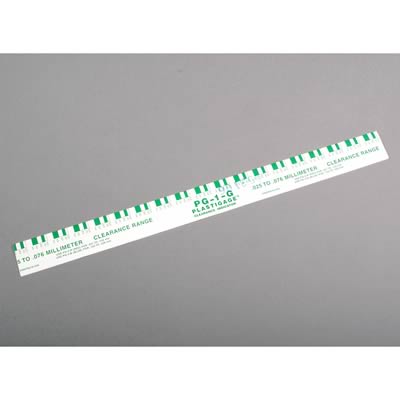
the bearing clearances you are just not that far off. but if it was my build ID break out the plasti-gauge and check it out,
Going to do that today.
your dial indicator may be the problem not the clearances and having a second check method is almost mandatory, remember
YOUR the BUILDER and its YOUR CALL, if its going to make you have sleepless nights, until it measures dead on, then by all
means have it polished again,
Are you thinking that the clearances are the problem ???
Most all my comments refer to the RUN-OUT of the crankshaft. One comment I made was to open up the oil clearances on
main #2, so that the run-out would have more room inside the bearing.
but like I said Ive seen many engines live long health lives having been built with FAR LESS CARE
and EFFORT than your putting into this. obviously the first step is verifying measurements, ID start with green plasti-gauge
btw
do you have snap gauges and mics?
Yes, I have a cheap set of snap gauges. The micrometers I have are nice ones.