TBucket Engine Project (Dart SHP)

grumpyvette said:
"have almost no concept of what a correctly tuned setup will feel like! "

I agree with this comment 100%. A challenge for me is since I’m relatively new to the hot rod scene not knowing what the “seat of the pants” actually feels like. You guys who have done dozens of builds and been around hot rods for a long time have an advantage here. Tires chirping taking off at a red light, stomp it at 50mph and the back end breaking loose and massive burnouts are also good indications that the tune is close. The AFR logging will help you visualize what your tune is doing and get you in the range but at the end of the day, it's the butt dyno that you need to tune towards. Feeling the instant torque is a cool feeling.
 
I can feel when I reach peak torque and am pulling just HP. Tuning is what makes a real car guy. I know allot of people who can bolt on parts. But the amount that get the most out of there engine is allot less unless its Saturday or Sunday at Lebanon valley speedway.
 
bytor said:
Looking good Rick, I used 6-32 for all my 650's orifices and found
that .059" was about as much you could drill them out and still use an hex wrench
as well. I was able to drill a few out larger near .070" and use a small star headed
screw driver.

Not Ideal, If had to do it over again, I would have went with 8-32 set screws in the
idle air bleed's. Thats the only orifice that would approach that size.

Sorry I've been out pocket today and didn't answer right back, had something
going on and that came first.

With the numbers I came up with, it looked to me that I had to go with 10-32 for
the air bleeds. If I wanted to go bigger than .074 inches, then I would need that
10-32 set screw. What I didn't consider if I only needed to go smaller, then the
8-32 would have done the trick. Partly I was being lazy, in that I didn't want to take
the carburetor off and and break it down to do more drilling later.


bytor said:
The HSAB and IFR change slightly based on carb size.
https://www.demoncarbs.com/Tech/SpecCharts.asp

If memory serves me correctly, the main problems I had with my setup were:

- rich tip in off idle.
- Transition circuit shut off too soon.
- Mains did not come online soon enough.
- A not so flat main fuel curve from too much emulsion.

Now keep in mind, carbs are a bit of science and witchcraft. I found that using
other folks experiences as a guide is very helpful but just because someone who
has a similar build as you do drills out their IFR to .035"and found nirvana doesn't
mean the same will work for you. Make one change at a time and log the results.
These things are balanced, meaning if you make one change, you will probably
need to make a change in another area of the carb. It's tedious but you will learn
a lot about carburetion.

Thanks for that link, I've been on the Demon website, but never ran across that
info. It was probably a good thing that I didn't know what the numbers should be
when I was mapping out all the orifices ...... It can skew the number you measure
when you think that I need to get a specific number.

I can see where I have the same problem with "rich tip in off idle". As I roll into
the throttle it goes even richer, from 12.x to 10.5 AFR. Can't say about the other
three statements yet.

I think there was some witchcraft involved with your LM-2, so yes I will have to
agree with you on that statement.

Modified cars (hotrods) are systems engineering problems at every step of the way.
There are no part numbers for the perfect carburetor or anything else for that matter.
If you just want a part number and it works perfect, then buy and drive a factory built
car such as Chevy, Pontiac or Ford.

The very reason I like cars, it's solving problems and wanting to build a better car than
the next guy!!!
 
Indycars said:

Modified cars (hotrods) are systems engineering problems at every step of the way.
There are no part numbers for the perfect carburetor or anything else for that matter.
If you just want a part number and it works perfect, then buy and drive a factory built
car such as Chevy, Pontiac or Ford.

The very reason I like cars, it's solving problems and wanting to build a better car than
the next guy!!!
Very well said
 

Below is the big picture of my setup to measure Exhaust Back Pressure. I would
prop up the gauge inside the car so I could see it when driving.

FP01_BackPressureMeasurement01_5772.jpg

Below you can see the 90° Elbow that has an AN fitting on one end with brass barb
screwed inside. The other end was a standard thread. I don’t remember the actual
size of the AN fitting, but a 7/16 inch drill bit only took out a small amount of
material for the 1/4 inch NPT tap.

FP01_BackPressureMeasurement02_5773.jpg

The first time I started the engine the pressure gauge was swinging with a min to
max variation of approximately 5-6 psi. I wanted a more stable needle so I tapped
the inside of the barb fitting for a 10-32 brass set screw. Then I drilled a small
orifice thru the set screw starting with a #60 (.040 inches). This really settled the
need down to about 1.5 psi. I thought that might be alittle small, so I increased it
to a #55 (.052 inches) drill bit. This seemed to have about a 2 psi variation.

FP01_BackPressureMeasurement03_5775.jpg
FP01_BackPressureMeasurement04_5777.jpg

Below is a link to a YouTube video I took with one hand using my iPhone 6. I edited
it in MS Move Make 2012 and then uploaded it to YouTube. Then I ran their Image
Stabilization filter, which really helps. But it made my text at the beginning and the
end dance around. Oh well, I shoot for a perfect world, but seldom get it.

YouTube

I watch my High Definition video and stopped it when the gauge was clear and drew
in the maximum reading with the Red Needle. We’re not looking exact straight at
the gauge so were getting some parallax error, but I would guess it to be 5 psi when
corrected.

FP01_CaptureGaugeMaxPressure.jpg

Now you have to consider that since I’m driving one handed, I can’t shift manual.
Therefore the 200-4R transmission shifts at about 3500 to 4000 RPM, I don’t know
if it would get worse or better at the higher RPM. I'm guessing that it would be the
worst at maximum torque, which is the highest volumetric efficiency. Maybe
someone here can tell me.

I’m a little concerned about the accuracy of the gauge at such a low pressure. If you
have a nice low pressure tire gauge for racing, that might work pretty well.

So what do you think, do I have a valid test??? Do I have too much back pressure and
need to change the baffles inside the exhaust extensions???


Last edited:
congrats on testing for exhaust back pressure!
SO FEW GUYS BOTHER and they rarely or almost never get the car correctly tuned as a result

Im assuming thats positive 5 psi exhaust pressure in the header collector with a muffler insert?
if you remove the muffler insert whats the gauge read?

viewtopic.php?f=56&t=495
grumpyvette said:
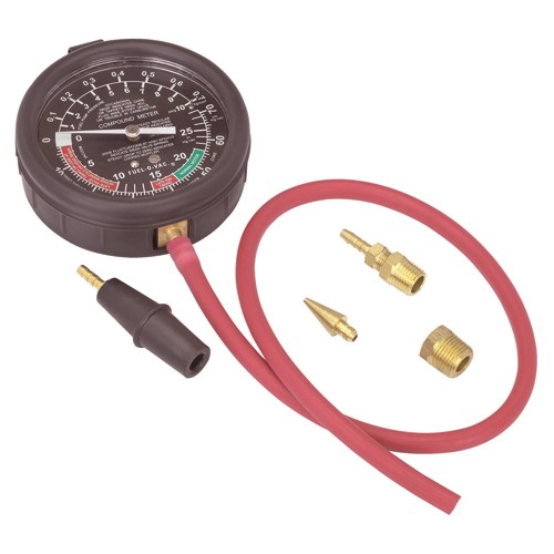
but what always amazes me is how few people bother to buy and use a simple vacume/pressure gauge to actually test and measure back pressure.
without, testing and having the facts,and knowing what your dealing with it seems foolish to rush out and spend hundreds of dollars on a new exhaust that may or may not solve your problems or to ignore a problem that you can easily test for and verify before spending any money on a problem you can prove is caused by a restrictive exhaust system, basing your parts selection on what your trying to accomplish, and whats required to reach your goal, rather than random guess work seems to be the cheaper route in the long run in my opinion.
drilling a small easily re-welded test hole in the header collector , or an adapter on an oxygen sensor bung gives you access for testing back-pressure
you might be surprised at what a few tests show you and how much time and money you can avoid wasting

you drill a 1/8" hole in the collector to insert a temporary test probe made from 1/8" copper tubing attached to a section of vinyl hose back to the test gauge, angle or point the end of the test probe tube,toward the exhaust exit not the engine, that hole you drill for test access can easily be brazed closed after the test, OR in an ideal world you weld a 1/8" Nation Pipe Thread bung on the collector, so you can test with a removable screw threaded adapter and close the threaded bung with a brass plug when your done, a buddy reads the gauge with the line run into the passenger seat and the gauge or in an ideal world you mount the gauge in the car as a reference for tuning


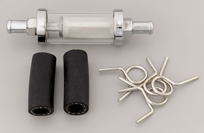
BTW if youve got one of these nearly worthless (for a true high hp application)fuel filters, that can break and cause a fire hazard,
9748.jpg

they can be quite useful inserted in the vacume line between the exhaust or intake your testing and the gauge your testing with as they make a rather effective pulse damper or reducer that limits the gauge needle rapidly twitching making it harder in some applications to get a clear reading, anything over 2-3 psi at peak rpm indicates an exhaust flow restriction thats costing you power
2713s.jpg

http://www.harborfreight.com/fuel-pump- ... 93547.html

you can,t make intelligent decisions without facts, and you get the facts by testing!
and it should be obvious that testing needs to be done under the current operational conditions at the rpm range that your concerned with.
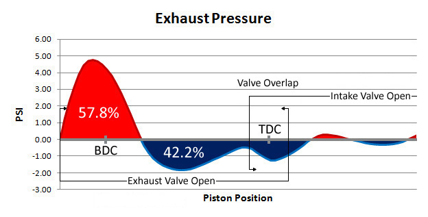
A stock automotive exhaust might have over 5 psi OF BACK PRESSURE, AT PEAK RPMS WHERE EXHAUST FLOW IS AT MAX,or even more in a few cases, of back pressure in the exhaust system if measured at the collectors at max engine rpm, with a decent accurate pressure gauge, while a good aftermarket exhaust system will roughly cut that in half to the 3-5 psi range. BUT An excellent performance exhaust will get down in the 1-2 psi or LOWER restriction to flow range at max engine rpm. 
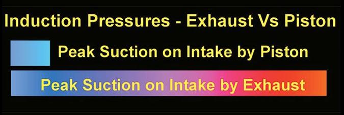
keep in mind that the efficiency of the headers scavenging the cylinders , and helping to draw in the following intake charge,is almost totally dependent on maintaining a very low flow restriction or back-pressure in the collectors ,especially at mid and upper rpm levels, any significant restriction to flow reduces the effectiveness of the headers ability to scavenge the cylinders by allowing the previous exhaust gas inertia mass to help drag in the next intake charge following it into that cylinder as it exits the cylinder thru the tuned headers primary's.
volumetric.gif

exhaustpressure.jpg

EXFLOWZ4.jpg


one of the most common and least tested, factors in most engine build ups is testing for restrictions to building increased horsepower. a huge problem is in restrictive exhaust systems that can not effectively allow the headers to scavenge the burnt gases from the cylinders, a good open collector on a well designed header can reduce the back pressure at the exhaust port to a negative pressure significantly increasing cylinder scavenging out the exhaust, thus helping draw in a fresh intake charge.[/b][/size]
is exhaust back pressure killing performance ?
 
grumpyvette said:
congrats on testing for exhaust back pressure!
SO FEW GUYS BOTHER and they rarely or almost never get the car correctly tuned as a result

I'm assuming that's positive 5 psi exhaust pressure in the header collector with a muffler insert?
if you remove the muffler insert whats the gauge read?

Thanks!!!

Yes that is a positive 5 psi.

That header extension has been on there for over 25 years now. I've tried to get it
off, but no cigar. That's after an initial attempt with PB Blaster and heat a couple of
years ago. Then I got them down from the attic and installed them, drove the car
several times and tried again with PB Blaster, heat and Freeze Off, still no cigar.

Then I would have to get the baffle out, that would be another adventure. It's possible
that I will replace the whole exhaust system, I could retest then. Really need to fix this
problem before I get into re-jetting the carburetor. Would that not change the tune
needed for the carburetor ?????

Do you think the Harbor Freight gauge would be more accurate ?????

 
Trying to ease into the winter time upgrade season. Thought I had a great idea
to put the jack stands on the dollies that I have, this way it would be so very easy
to go underneath and roll the car around to work on the many things I have planned.

But when I tried to roll the car around, one dolly would twist while the other would
stay straight relative to the car. I just did not feel like it was a safe solution and
most likely would end up scratching the paint when it twisted too far and came off
the radiator hose.


RaisedOnDollys_5784.jpg


Many have already thought of this tip, but have not seen it posted here. I have some
1 inch radiator/heater hose that I slit lengthwise. It works really nice in that it will
cup the axle and stay where I put it. Hell of lot easier than using rags and trying to
get them to stay put.

The one inch hose works great on the front axle that is 1-3/4 inches in diameter, but
the rear axle could use some 1-1/2 hose. Although the one inch hose is staying put so
far.


RaisedOnDollys_5786.jpg
RaisedOnDollys_5789.jpg
 
Last edited:
first let me say that I really like the way the car looks in this posted picture!
RaisedOnDollys_5786.jpg


then ID point out that your hardly the first guy to find out that the jack stands placed on the roller dolly config is not ideally stable , but that does not mean you can,t make a huge improvement in that stability issue rather cheaply, by doing what several of my friends did, you simply place the jack stands as far apart as you can where they support the car and measure the outside corner dimensions, and you cut a sheet of 3/4" plywood to that size to fit on top of the dollys , you then drill 4 holes thru each dolly and use bolts fender washers and nuts to secure the dollies to the underside of the plywood, you then accurately measure the angle of the jack stand legs and cut short sections of pressure treated 2x4 on one edge with a miter saw so you can place THREE sections on the THREE sides of the jack stand base that don,t face outward like the lug nuts, this allows the jack stands to be slid into place or removed but prevents them from tipping.
once you build both a front and rear matched pair or dolly support jack stands (MARK EACH AS THE WIDTH MAY BE DIFFERENT) youll want to WELD some eye bolts to the jack stands and fabricate a few easily adjustable connection bars from 3/4" EMP electrical conduit and J&B weld in adjustable length brace rod ends that allow you to move the car while keeping both the front and rear stands effectively locked in a firm relationship yet have the cross braces easily removeablr
038613125032a.jpg

jssupo.png

RaisedOnDollys_5784a.jpg
 
Rick find a way to bolt the jackstands to the dollies, that will stop them from moving. Or you could build a set of stands made special for that purpose.
 
Some great ideas Grumpy!!!

I wondering how do you get the jack in there to lift the car with a board going

across between the two dollies ??? The orange lines represent where the board
would hit the jack. I would have a similar problem in the rear.


RaisedOnDollys_5794.jpg

Just putting the car on the dollies directly, I get an additional 3-1/2 inches of
ground clearance.


RaisedOnDollys_5792.jpg

Any ideas???
 
Last edited:
busterrm said:
Rick find a way to bolt the jackstands to the dollies, that will stop them from moving. Or you could build a set of stands made special for that purpose.

It's not twisting between the dolly and jack stand. It's twisting between the
car and jack stand.

 
Well after I posted that I wondered about that! I imagine you could make a set of jack stands that clamp to the front straight axle and the rearend housing. and put the hose around the axle and housing and clamp the stand around it.
 
Does that make any sense? How tall would the jack stand have to be off the dollies? What diameter are the front axle and rearend housing? Oh yeah what is the distance between the aluminum channel on the dollies?
 
busterrm said:
Well after I posted that I wondered about that! I imagine you could make a set of jack stands that clamp to the front straight axle and the rearend housing. and put the hose around the axle and housing and clamp the stand around it.

Does that make any sense? How tall would the jack stand have to be off the dollies? What diameter are the front axle and rearend housing? Oh yeah what is the distance between the aluminum channel on the dollies?

I think it's making it overly complicated to clamp them to the axle, once the front
or back set of dollies are locked together they can no longer rotate independently
of each other. That should solve the problem.


Next chance I get I'm going to stop by the scrap iron place to see if they have
some angle iron. I'm going to need the front piece to be 6 foot and the back
piece to be 6-1/2 foot.

 
bytor said:
Your MAP signal looks odd. If I'm reading it right your at 6hg when
your at WOT.. Thats not right is it?

I haven't forgotten this comment by Bytor, I new he was right as soon as I read
it. So in my last Amazon order I purchased a "Standard Motor Products AS5T MAP
Sensor" for $16.40. I connected the AQ-1 again and started calibration on the new
Map Sensor, but realized I must have done the first one wrong. So after I completed

calibrating the new sensor, I put the old sensor back on and went thru calibration
again. The old sensor was just fine, voltage at a specific vacuum level only differed
by a few tenths of a volt from the new sensor.

Looks like I have a backup Map Sensor now!!! :D

http://www.amazon.com/gp/product/B004BT ... UTF8&psc=1


MapSensor.jpg
 
Last edited:
To keep busy between thinking about the wiring, I've been polishing the valve
cover tops. I say tops because they are two piece valve covers, maybe next
winter I will get to polishing the sides.

First you got to start with block sanding to get the surfaces flat. I stayed with
the block until I got to 1000 grit, then I went to using my handing. At 1000 grit
it felt like the sand paper was hydroplaning on the water.


FP04_BlockSandingW600Grit_5828.jpg

You can see the difference between the 320 and 2500 grit surface below.

FP04_SandingComparison_5808.jpg

Finished product !!!

FP04_VavleCoveFinishedCloseUp_5815.jpg
 
Last edited:
I have to do all my billet on my engine it is definitely pretty scratched up. I have used my rotary buffer also with mothers while still mounted on the heads
 
Back
Top