My Cam Research for the Experts Eye


I ordered one of these tools , you don,t use them that often,
but they are inexpensive and save you a great deal of time,
and effort when you're doing some jobs,
so well worth the cost to own

1_590x_217c64c8-9167-4f79-9831-d6fccd81e590_1024x1024@2x.jpg


giphy_480x480.gif
 
Last edited by a moderator:
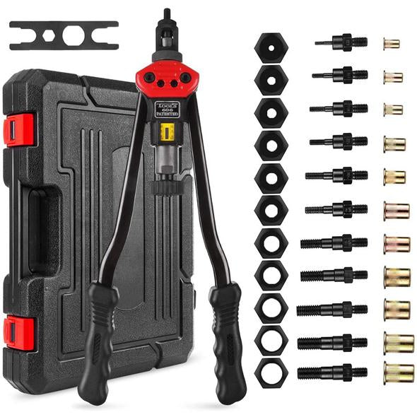
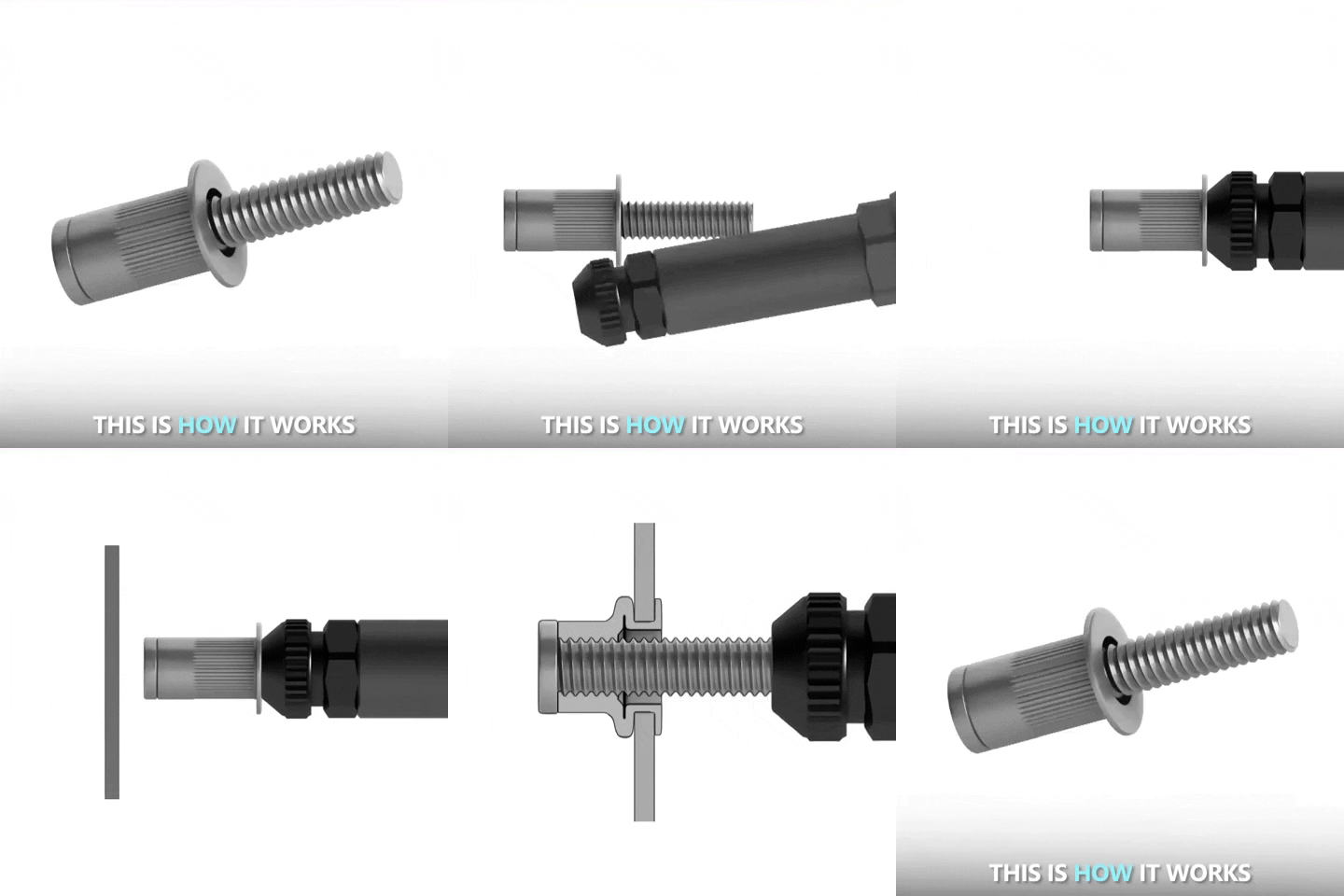
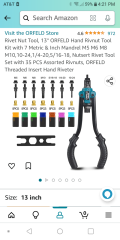
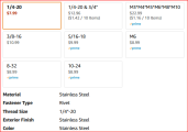
This was what I bought off Amazon, it was $36. There's a lot of these probably from the same factory. It's worked great. There's videos on using a bolt and a nut to install but this makes it a breeze. You can still use the bolt/nut for inaccessible spots. I have a drill bit set in 1/32 increments, so once I figured out the right size hole to drill for each nutsert I marked it on the box for easy reference.
Screenshot_20230609-162125.png
Frame had holes from years ago from fuel line install so I used those wherever possible for the nutserts to fasten the new hard lines. Couple different spots here...
20211112_152219_resized.jpg
20211206_160331_resized.jpg
 
Last edited:
This was what I bought off Amazon, it was $36. There's a lot of these probably from the same factory. It's worked great. There's videos on using a bolt and a nut to install but this makes it a breeze. You can still use the bolt/nut for inaccessible spots. I have a drill bit set in 1/32 increments, so once I figured out the right size hole to drill for each nutsert I marked it on the box for easy reference.
View attachment 17754
Frame had holes from years ago from fuel line install so I used those wherever possible for the nutserts to fasten the new hard lines. Couple different spots here...
View attachment 17756
View attachment 17755
Awesome yes I plan on using one of these when I do my fuel system install originally had purchased self tapping screws and hangers other idea I had was welding bolts to the frame. This tool seems like a great option for this though. Thank you for sharing and thank you Grumpy for the links. I appreciate you guys.
 
Glad to share after all the help I've gotten.
Something that was helpful to me - I took a piece of sheet steel and tried out 8/32, 1/4 and 3/8 nutserts to get a feel for what it took to set them with the tool. I did buy the 8/32 anvil separately if I remember right, pack of 2 as the smaller they are the easier they can break. I've also since bought packs of the nutserts to have plenty on hand.
This was helpful to me as I could see force needed vs nutsert compression from the back.

Another example is in engine compartment - the panels on the left are retained with 10-32 button head allen screws into nutserts, as is everything else, like fuel regulator, line lock, prop valve, wiring harness clips, brake lines etc. Very clean and super easy to attach or remove, no more fishing bolts through the metal.
20230602_143756_HDR_resized.jpg
20230602_143958_HDR_resized.jpg
 
Last edited:
I agree why I plan on investing in one looked even saw nuematic ones on Amazon but if I can save some coin right now it would help finishing my build is definitely hurting cash wise but don't see inflation taking a break on us for a bit.
 
This may be a bit convoluted to follow but it relates to looking at what was done before vs how I'd do it today.
In the first build, I made my own front and mid mounts to get the big block exactly where I needed it to be. This setup has worked for 30 years. This go-round I refined the front mounts, added new pads but basically kept the design the same.
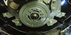
20221129_134425_HDR_resized.jpg

Please note I specifically don't want to go back and install side mounts. I considered them but decided to go with what I had. Header clearance in the driver side is super tight and with the current mounting arrangement everything fits.

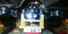
The mid mounts actually bolt to the transmission housing and through it to the block. Right now I've got 1/2 in spacers since the trans isn't in place. That's a temporary wood support to ensure no surprises as I work under the car. It can't stay as its in the way of the starter and the headers.
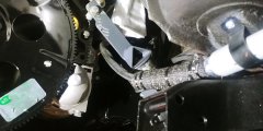
20221123_143817_HDR_resized.jpg
20221111_115306_HDR_resized.jpg


This design works well with an engine/trans bolted together and can support the engine no problem. But I've got concerns about running the engine by itself with this bracket arrangement. My concern is about vibration - if the single bolt connection loosens, it may allow the engine to shift or worst case to drop a few inches. Could be a disaster. Note that this isn't an issue with engine/trans rigidly bolted together, this is for engine running by itself. And I'm not ready to rebuild the th400 yet, I need to get this engine going and to verify all is well before going further. So I'm changing to a minimum of two attachment points on the bell housing. In this case it's actually 3 attachment points. I also don't want to install the usual .090" mid engine plate that's sandwiched between engine and trans.

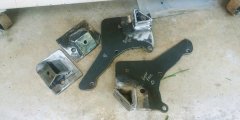
This is what I have now. In calculating the loads, this is .125" material which has held the weight ok for the past 30 years in a generally triangulated form - again, reminder that this was for an engine/trans bolted unit. However the weakness in just having the engine by itself running is in the bolt tightness and single point of contact. So I decided its time for a change.
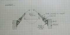
5112023174623.jpg

This is what I'm making, should be pretty straightforward. Contact has been changed to 3 bolt attachment each side for stiffness and less load per bolt, plus just moderate tightening is needed. I've also significantly increased material thickness. This setup also applies direct downward load vs the previous setup with load going out diagonally. I use the same bolt locations thru the frame and just have to make the new frame mounts and support brackets for each side. I'm not making it a one piece engine support bracket because that wastes more plate material to cut the shape and doesn't really gain more structural support. This is pretty much easy cut/shape and welding. But mainly this provides a much more solid support structure for a running/vibrating engine without trans installed and very strong structure when everything is bolted together.
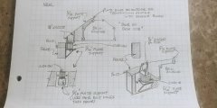
5112023174519.jpg

Crazy? Lol maybe so! I'll post up the finished version when its done.
 
Last edited:
why not temporarily fabricate a sturdy wood box and place/ stack a couple of thick rubber pads
between the box and the engines oil pan.
of the correct height to take 90% of the engines weight off the rear motor mounts to temporarily keep it well supported
during engine test runs, its not like your driving anyplace without a transmission.
measure carefully, jack the front of the car up 2" slide the padded box under the oil pan and lower the front of the car , just enough so the weights off the rear engine mounts
Thanks Grumpy, I considered that temporary setup but decided I liked the 3 point brackets better for the long term. Something I had noticed was that with the angled supports, the rubber biscuits were also deformed at an angle and the engine weight was resting against the threaded rod through the biscuit to some extent. Not sure if this made a big difference anywhere to be honest, but the more I thought about it, the more I preferred the flat sit of the new brackets where the entire weight of the engine was taken evenly by the biscuits.

EDIT this is why I value your input...you got me thinking about the temporary engine run vs long term with complete driveline. The angled supports worked great for 30 years but I did want more than 1 point of attachment. But ... maybe I'm remaking too much stuff. So I'm reworking to keep the frame mounts as-is , but am simply re-doing the engine bracket to catch more of the bell housing bolts.
Rather than post 20 more times , I'll get that done and show results.
Thank you for constructive feedback!
 
Last edited:
Here's what I've got so far, just working a few hours in the morning each day....

Just reference, this is what the old rear engine mount setup looked like
5142023134749.jpg

I've also thought about this engine rebuild (hopefully) producing more hp and torque, thus a careful look at all mounts was needed. Front mounts are .25 steel and are super strong, no worries there.

I re-did the frame brackets using .25 angle vs old .125 angle
512202318558.jpg

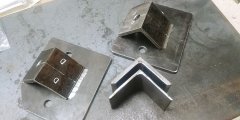
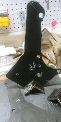
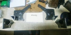
After lengthy cardboard template making/checking/trimming, I made sure both of the bellhousing brackets had the same shape - they bolt through the transmission bellhousing into the block, thus the shaping. As I mentioned this is not a .090 plate between engine and trans, this set up bolts to outside of trans bell housing.
20230614_110311_HDR_resized.jpg

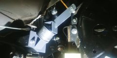
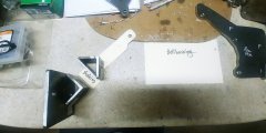
Each engine bracket will get welded to a triangular base. This will fit onto the frame bracket bushing and to the engine.
20230614_115648_HDR_resized.jpg

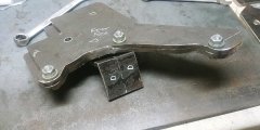
Here's the overall configuration - I'll use .75 spacers when I bolt to block since the trans won't be in place. The spacers will keep the brackets square to the block. All steel is now .25 thick
Rick's sharp eyes will see extra hole in driver side bracket, that's for oil sender tube. I'm putting sender and switch slightly away from the block fitting for header clearance. More on that later.
20230614_133348_HDR_resized.jpg


Big difference from original supports20230614_133417_HDR_resized.jpg

Tomorrow I'll get it all welded and ground smooth. After that a final fit check and paint.
 
After last fit check on the car, everything's welded up. My welds are structurally fine, but not that set of stacked dimes. But I've got a burr bit and some glazing putty lol.

So last pass will be to clean up surfaces and paint. I'm happy with this setup.
516202313462.jpg
 
Looking good again!

Every weld has been filled with putty and sanded smooth on the entire frame.

FP01_RearShockMounting_6187.jpg
 

TXChevy,​


Indycars

its really impressive to see custom fabricated components used rather than limiting your builds to off the shelf parts​

 
Thanks to both of you, as I've mentioned I appreciate your comments.
Rick, I've looked closely at your t-bucket (and engine) build threads, got lots of incentive for my work. The beautiful welds you pointed out are just a small example of the meticulous work you did.
Grumpy, I honestly get more satisfaction from making stuff vs buying everything. My stuff may not have cnc precision but I think the end result looks good and works. Plus it seems that quality is falling and costs are rising. Yes sometimes I buy stuff, such as the throttle return plate for the carb but as example, at the same time I made the wire loom holders at the valve covers and set up the downshift microswitch at the carb. And of course nobody makes that rear engine mount in that configuration :) Lots of satisfaction.
 
Rick, I've looked closely at your t-bucket (and engine) build threads, got lots of incentive for my work. The beautiful welds you pointed out are just a small example of the meticulous work you did.
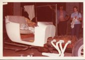
I didn't know you read other threads, I've not seen any comments. The welding on the frame was done by David Elledege, with a stick welder, but I did all the body work on the welds while in college on weekends. That was probably in 1978, just 45 year ago! Ok that's enough of hijacking your thread. Thanks for letting me go back in time!!!

Back to the regularly scheduled program.

TBucketOriginal1980Version-(6)Small.jpg

.
 
Back
Top