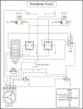
Is this what you are suggesting, surely can't be that easy. Then the "Horn Feed In"
must supply power to all the outputs, not just the horn. IIRC, the Yellow wire is
larger than the other wires.
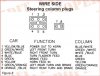
NOT A TA said:I'm colorblind so it's very hard for me to follow color coding if things aren't in the same order.
I don't see front parking light wiring from the light switch.
Are there 4 way hazard flashers?
Are there dash indicators for turn signals and High beam?
Horn, brake light, and headlight switch should get power from the always on fuse panel but what is the other wire from the panel to the column for? Turn signals should be powered from keyed power fuse panel.
What is the PXL in a circle?
") . I guess he could use dual filament light for the front turn/parking light.
. I guess he could use dual filament light for the front turn/parking light.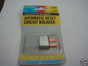
mathd said:Well this is almost it.
Remove the connection form both the stop/turn light C and F to the brake switch B.
Done
And do NOT connect both flasher/stop light F and C together.
Don't understand what you are saying above.
Then have the Brake switch B connection to the always-on power.
Done
This should be doing it if i understand correctly..
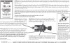
Do you have any more info on the hardware(manual) so i can get a better understanding of it all?.
Did you need more info other than the headlight
switch manual I posted last night???
NOT A TA said:I'm colorblind so it's very hard for me to follow color coding if things aren't in the same order.
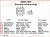
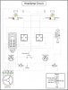
Maybe this will help. Each connection on the steering column is referenced
by the letter corresponding to the drawing. I didn't have the table from Ididit
when I made the drawing for the steering column.
I don't see front parking light wiring from the light switch.
I won't have parking lights in the front, just turn signals. If I need to be seen,
the headlights will be on.
Are there 4 way hazard flashers?
Yes I'm planning on 4-way flashers. What do I need,
just a second flasher, need to do some research to see.
Are there dash indicators for turn signals and High beam?
Dash turn indicators are in the speedometer.
Horn, brake light, and headlight switch should get power from the always on fuse panel but what is the other wire from the panel to the column for? Turn signals should be powered from keyed power fuse panel.
I thought the "Horn Feed In" yellow wire supplied power to all the outputs. If
so then the turn signals would also get it's power from the yellow wire or
always on fuse panel.
What is the PXL in a circle?
Turn signal flasher.
mathd said:Do you have any info on the steering column? layout/diagram/schematic?
busterrm said:Glad you are making progress, I will be able to drive up a week from this Friday.