My 1st. Street 383 Build

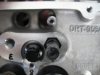
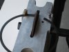
Looks good to me. But the 2nd and 3rd pics are hard to tell anything, since the background is dark by having the spring behind it as it's background. The witness mark pretty much tell you what you need to know.

All I can say is I did it for only one cylinder, intake and exhaust. You certainly can't go wrong by checking all the valves. It just might catch some other problem, but related to the valve train.
 
bytor said:
I think I got my pushrod length sorted out. I started with a 7.150 pushrod length and it seemed to be a bit off center towards the exhaust.
Then I went with a 7.0 and it was off center towards the intake.
Ended up with a 7.100 and its centered and has a narrower swipe. (.085 vs .110)


Since this is an important setup step, feedback from the experts is welcome. Do I need to perform the pushrod length test for ‘all’ the other cylinders or is checking one good enough?


depending on my mood and time requirements I generally check at least all four end cylinders at a minimum, just to be sure, but most Of the time Im in no hurry so I check them all. and before you ask, yes occasionally you'll find differences but most of the time they check out being similar, so while it may be ALMOST a waste in time I feel better KNOWING, and yes youll most likely be just fine, you have already done more careful checks than about 70% of the guys I know do when they install a cam


BTW LOVE THE CLEAR PICTURES
 
grumpyvette said:
depending on my mood and time requirements I generally check at least all four end cylinders at a minimum, just to be sure, but most Of the time Im in no hurry so I check them all. and before you ask, yes occasionally you'll find differences but most of the time they check out being similar, so while it may be ALMOST a waste in time I feel better KNOWING, and yes youll most likely be just fine, you have already done more careful checks than about 70% of the guys I know do when they install a cam

Thanks for the feedback. Yes, I'm in no hurry and kind of figured I knew the answer before I asked.

I did notice during this exercise that it was hard to get a good clean rocker wipe mark on the valve stem. I was using a sharpie to mark the valve tip. With the roller tip, there didn’t seem to be enough rubbing action to make a clean mark. I mean, you could see it but it was faint. I discovered if you also mark the rocker roller tip, you will get better and consistent results. I think it adds just enough friction to make a decent roller travel pattern.
 
http://www.highlandwoodworking.com/star ... ye4oz.aspx
061531.jpg


ISG806_2.jpg

machinist blue dye used on a Q-tip shows the wear far faster
 
I ran into a snag. How common is to for the pushrod holes in the head not to align with the lifter bores completely? I have 3 that the pushrod touches the head when the rocker is aligned correctly. How complicated is it to clearance the head area where the pushrods touch to correct this and how do you go about doing it?
 

Attachments

  • IMG_0349.JPG
    IMG_0349.JPG
    42 KB · Views: 111
  • IMG_0353.JPG
    IMG_0353.JPG
    26.5 KB · Views: 111
having the rush rods rub the side of the slots in the head casting is not all that common, but having the push rods rubbing the ends of those clearance slots when you change rocker ratios IS rather common. youll obviously need to drill out the slot for the required clearance.
Id trial assemble the rocker and push rod then carefully mark the head in the area that needs clearance work, Id be a pass with a sharp 1/2" drill will provide the required clearance.
most guys remove the intake manifold, fill the lifter gallery with clean rags , and drill the slot to a larger diam. while holding a shop vacuum cleaner with the tip of the suction hose under the head in the lifter gallery, to suck up chips the drill produces as they fall to prevent them from getting into the engines lifter gallery

THESE THREADS HAVE INFO YOU CAN USE


viewtopic.php?f=52&t=126&p=1193&hilit=ratio+rockers+louis#p1193

viewtopic.php?f=27&t=3379&p=8922&hilit=shop+vacuum#p8922

viewtopic.php?f=52&t=462
 
Is clearancing just enough so the pushrod doesn't touch the head good enough or is there a figure to shoot for?
 
bytor said:
Is clearancing just enough so the push rod doesn't touch the head good enough or is there a figure to shoot for?

from a pragmatic out look, if it clears by a few thousands, all thru its cycle, it will function but I generally try for .030 minimum side slot clearance and .060 minimum end of slot push rod clearance, keep in mind the push rod moves as the rocker moves so you need to check push rod to slot clearance at several points in the cam rotation, thats why mos guys drill the clearance holes in the heads fairly large and let the push rod guide plates keep the push rods aligned.

machinistcaliper

swirlpicd.jpg

head+rocker_bolt_boss.jpg


Id point out that MEASURING BEFORE cutting is helpfull as on some heads the amount of metal between the push rod and the intake port side wall is rather thin. so you can,t just drill the hole with wild abandon, thinking youll never cause problems
 
grumpyvette said:
bytor said:
Is clearancing just enough so the push rod doesn't touch the head good enough or is there a figure to shoot for?

from a pragmatic out look, if it clears by a few thousands, all thru its cycle, it will function but I generally try for .030 minimum side slot clearance and .060 minimum end of slot push rod clearance, keep in mind the push rod moves as the rocker moves so you need to check push rod to slot clearance at several points in the cam rotation, thats why mos guys drill the clearance holes in the heads fairly large and let the push rod guide plates keep the push rods aligned.
Id point out that MEASURING BEFORE cutting is helpfull as on some heads the amount of metal between the push rod and the intake port side wall is rather thin. so you cant just drill the hole with wild abandon, thinking youll never cause problems

Your correct, the pushrod hole is very close to the intake wall is thin so I only want to remove just enough was my thought. It is scary grinding away on nice new heads... Thanks for the guidance Grumpy!
 
Getting ready to set the gap on my rings using the Proform 66785 tool. I have successfully done one and it’s definitely one of those things you need to get a feel for. The info in Indy’s build post and this video has been very helpful getting me started. Below is my ring info and JE recommended end gap based on my bore size. Any reason not to stick with JE gap recommendations?

Ring Specs:
Top Ring – JE ProSeal J14040-2-1.2CNR
Carbon Steel Nitride, Barrel Face
Back Cut, Torsional
Axial Height 1.2, Bore 4.040
JE Recommended End Gap -Min. Gap Per Inch Bore = 4.040x.0045=.018”

2nd. Ring – JE ProSeal J24040-5-1.5IPE
Iron Phosphate, Napier
Back Cut, Neutral
Axial Height 1.5, Bore 4.040
JE Recommended End Gap End Gap -Min. Gap Per Inch Bore = 4.040x.0050=.020”

Oil Ring – JE ProSeal J34040-03.0HCUF
Carbon Steel Chrome, Full Seal
Flexvent, Tension 15-16lbs
Axial Height 3.0, Bore 4.040
JE Recommended End Gap End Gap –Min. Gap = .015”
 

Attachments

  • Drawing3.jpg
    Drawing3.jpg
    299 KB · Views: 79
bytor said:
Getting ready to set the gap on my rings using the Proform 66785 tool. I have successfully done one and it’s definitely one of those things you need to get a feel for. The info in Indy’s build post and this video has been very helpful getting me started.

You might want to check out this topic that I posted about the Proform tool.

Proform 66785 Ring Filer Modification
viewtopic.php?f=50&t=4681&hilit=ring+end+gap

Glad I could help, that's partly why I posted all that info.

 
Oil ring question. It would seem The oil rings came out of the box with a .018-.020 gap without any filing. The minimum recommended by JE is .015. I assume this is nothing to worry about but what would be an oil ring gap that would be considered 'too large'?
 
bytor said:
Yep, I did the brass tubing trick on one of the alignment post of the 66785 and it produces perfect gap alignment.

No doubt you are paying attention and taking your time. Just getting done is not your priority.
 
bytor said:
Oil ring question. It would seem The oil rings came out of the box with a .018-.020 gap without any filing. The minimum recommended by JE is .015. I assume this is nothing to worry about but what would be an oil ring gap that would be considered 'too large'?

Talked to JE today and as expected, not a critical measurement. They said anything in the .015 - .045 range was good. Seems a bit of a wide range to me but what do I know :D
 
the oil ring end gaps basically not that critical as they function as wiper blades on the cylinder walls, the inner spacers simply a drain clearance and spacer, forcing trapped oil on the bore walls up and in thru the piston ring drain holes in the bottom of the oil ring groove.
oil rings are cooled effectively by the oil flow and don,t expand as much as upper rings because they never get subjected to similar heat levels

ATV-EnginePistonRing4.jpg

oil_consumption_piston_rings.jpg
 
grumpyvette said:
the oil ring end gaps basically not that critical as they function as wiper blades on the cylinder walls, the inner spacers simply a drain clearance and spacer, forcing trapped oil on the bore walls up and in thru the piston ring drain holes in the bottom of the oil ring groove.
oil rings are cooled effectively by the oil flow and don,t expand as much as upper rings because they never get subjected to similar heat levels
ATV-EnginePistonRing4.jpg

oil_consumption_piston_rings.jpg

Good pictures, It got me thinking, the only oil supply a stock small block cylinder walls receive is whats slung of the crank correct?
 
bytor said:
grumpyvette said:
the oil ring end gaps basically not that critical as they function as wiper blades on the cylinder walls, the inner spacers simply a drain clearance and spacer, forcing trapped oil on the bore walls up and in thru the piston ring drain holes in the bottom of the oil ring groove.
oil rings are cooled effectively by the oil flow and don,t expand as much as upper rings because they never get subjected to similar heat levels
ATV-EnginePistonRing4.jpg

oil_consumption_piston_rings.jpg

Good pictures, It got me thinking, the only oil supply a stock small block cylinder walls receive is whats slung of the crank correct?

for a stock engines thats basically correct!, but your not going to starve for oil in a stock application, in fact in a few applications too much oil is a potential issue
crankoilcv.jpg


RELATED THREAD
viewtopic.php?f=54&t=64
 
Hi grumpy, RustOleum seems to be one of your preferred engine block paints. When using it in the exterior of the block, do you use it in conjunction with the RustOleum high temp primer or just go with the high temp color coat straight on the bare block. Meticulously prepped and cleaned block of course.
 
Back
Top