You are using an out of date browser. It may not display this or other websites correctly.
You should upgrade or use an alternative browser.
You should upgrade or use an alternative browser.
My 1st. Street 383 Build
- Thread starter bytor
- Start date
bytor
Well-Known Member
Piston ring orientation question. I understand this
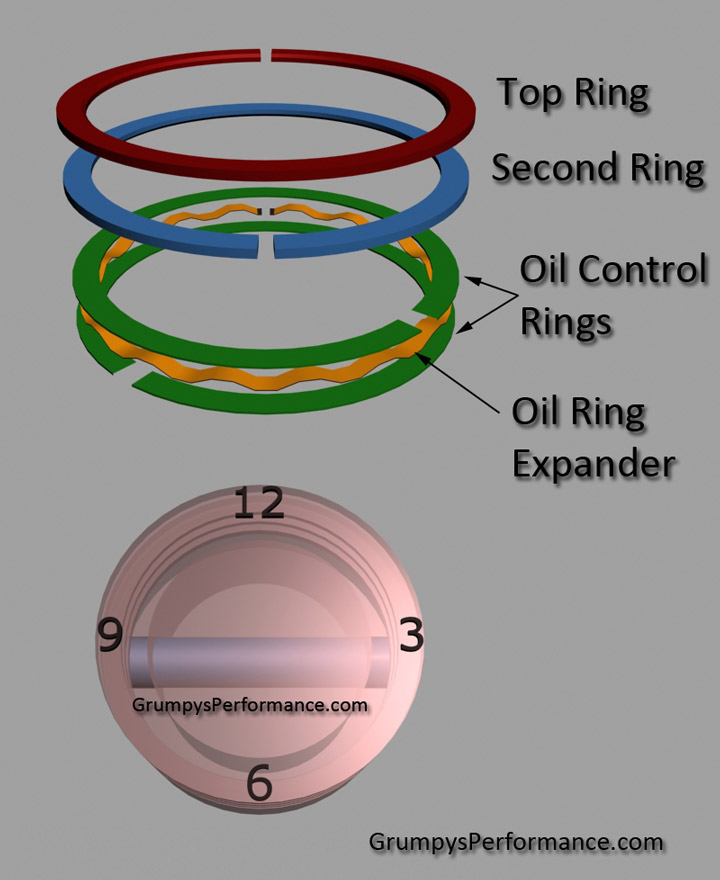
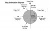
But what I'm a little unclear on is the orentation of the piston rings to the block. I assume the top compression ring gap should always be at the 12 o-clock position (towards the cam) regardless what side of the block it's on. The diagram below that cam with my rings shows it different on each side.
I may be looking at it wrong.
Attachments
bytor said:Piston ring orientation question. I understand this
But what I'm a little unclear on is the orientation of the piston rings to the block. I assume the top compression ring gap should always be at the 12 o-clock position (towards the cam) regardless what side of the block it's on. The diagram below that cam with my rings shows it different on each side.
I may be looking at it wrong.
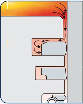
piston rings move both in and out of the piston grooves and rotate as the piston moves thru its 360 degree rotation, keep in mind its the ring groove SPACING, and gap indexing and relationship to the rings, that is designed to minimize the loss of cylinder pressure thru the ring gaps, thats key, here, not where the gaps are exactly located ,because each ring tends to rotate at a different speed in its piston ring groove, piston rings rotating between 3-8 rpm in the piston grooves at higher rpm ranges is fairly common. because the fact is that piston rings do tend to rotate in the piston groves in most engines, and its rare to find the ring gaps in the same location once the engines been run for several hours. Id also point out that failure to have the bore honed with the correct deck plates tends to reduce the ring seal. in fact having the rings rotate in the piston grooves tends to reduce bore wear, and keep the grooves clearance free from carbon build up
READ THESE LINKS and sub linked info
viewtopic.php?f=53&t=5454&p=16301&hilit=groove+rings#p16301
viewtopic.php?f=53&t=4602&p=12273&hilit=piston+rings#p12273
viewtopic.php?f=53&t=509&p=12277&hilit=piston+rings#p12277
viewtopic.php?f=53&t=4630&p=12416&hilit=piston+rings#p12416
viewtopic.php?f=53&t=110&p=3631&hilit=hone+plate#p3631
viewtopic.php?f=53&t=3897&p=17251&hilit=piston+rings#p17251
viewtopic.php?f=51&t=976
bytor
Well-Known Member
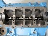
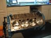
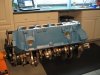
Quick update on the build. I have started the final assembly. Lots of cleaning, painting and prepping mostly but making good progress.
I went ahead and replaced the cam bearings much like Indycars did. I had a few nicks from pre-assembly that bothered me but all good now. I also used Indy’s technique to install and lube the cam by positioning the block upright and dropping the cam in, very easy. Thanks for the Tip Indycars..
Started installing the pistons and screwed up on the 1st one. Not a good confidence builder. I think I didn’t have the assembled piston all the way in the ring compressor correctly and it ate one of my oil rings. No other damage done and have another on the way. All the other pistons went in without issues.
Attachments
viewtopic.php?f=53&t=509&p=11921&hilit=ring+compressor#p11921
ITS VERY EASY TO BUST RINGS IF YOU DON,T KEEP THE RING COMPRESSOR SOLIDLY FLUSH WITH THE BLOCK WHILE THE PISTONS SLID, thru the ring compressor and down INTO THE BORE!
ID tell you I know that only because, Ive screwed up and caused similar ring failures in the past, so your hardly alone, its part of gaining experience!
you can be absolutely sure the vast majority of people who have assembled several engines have screwed up a ring at some time in their lives
bytor said:I went ahead and replaced the cam bearings much like Indycars did. I had a few nicks from pre-assembly that bothered me but all good now. I also used Indy’s technique to install and lube the cam by positioning the block upright and dropping the cam in, very easy. Thanks for the Tip Indycars..
Sweet....glad it worked for you!
Started installing the pistons and screwed up on the 1st one. Not a good confidence builder. I think I didn’t have the assembled piston all the way in the ring compressor correctly and it ate one of my oil rings. No other damage done and have another on the way. All the other pistons went in without issues.
Where did you find the broken piece of ring, did it fall outside the cylinder???
bytor
Well-Known Member
Indycars said:Where did you find the broken piece of ring, did it fall outside the cylinder???
No, after I got the piston installed, I noticed a 'shiny' streak in the cylinder (about crapped my paints). Not a scratch thank goodness. When I pulled the piston out for investigation, I noticed the edge of the ring that is broken off in the pic was between the piston and cylinder wall still kinda attached to the ring. No other damage noticed. I paid extra attention with the other cylinders looking for marks on the cylinder walls during and after installation.
bytor said:No, after I got the piston installed, I noticed a 'shiny' streak in the cylinder (about crapped my paints). Not a scratch thank goodness. When I pulled the piston out for investigation, I noticed the edge of the ring that is broken off in the pic was between the piston and cylinder wall still kinda attached to the ring. No other damage noticed. I paid extra attention with the other cylinders looking for marks on the cylinder walls during and after installation.
You must be living life right!

bytor
Well-Known Member
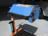
A few more progress pics.
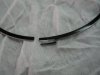
The Piston install tool/Rod guide tool I made and used during the piston install.
(A clip from http://forum.grumpysperformance.com/viewtopic.php?f=53&t=247&p=293)
Piston install tool: (Rod Guide Tool)
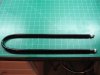
always protect the connecting rod journals from getting scratched during the rod assembly process, a 18" long section of 3/8" or 7/16" inside diam. rubber fuel line can be pushed over rod bolts, after being looped 180 degrees around the rod journal on the crank, if the rod bolts extend down from the rod or a 18" section of 7/16" fuel line with a u shaped section of 5/16" thread rod that's 24" long, bent in the center over a 2.5" section of pipe so the ends remain parallel and even in length can be used as a handy tool so that 3" of the thread rod extends from each end, you then cover all but the last 1" on each end with plastic electrical tape and place the ends thru the rod bolt holes, and thread on a nylon washer and a nut finger tight, can be used as a tool to draw into place a rod on the rod journal if you use cap-screw rod designs
The Piston install tool/Rod guide tool I made and used during the piston install.
(A clip from http://forum.grumpysperformance.com/viewtopic.php?f=53&t=247&p=293)
Piston install tool: (Rod Guide Tool)
always protect the connecting rod journals from getting scratched during the rod assembly process, a 18" long section of 3/8" or 7/16" inside diam. rubber fuel line can be pushed over rod bolts, after being looped 180 degrees around the rod journal on the crank, if the rod bolts extend down from the rod or a 18" section of 7/16" fuel line with a u shaped section of 5/16" thread rod that's 24" long, bent in the center over a 2.5" section of pipe so the ends remain parallel and even in length can be used as a handy tool so that 3" of the thread rod extends from each end, you then cover all but the last 1" on each end with plastic electrical tape and place the ends thru the rod bolt holes, and thread on a nylon washer and a nut finger tight, can be used as a tool to draw into place a rod on the rod journal if you use cap-screw rod designs
Attachments
bytor
Well-Known Member
Indycars said:
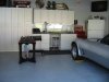
Is that the kitchen, I just thought he had a sink in the garage???
Wish I had a sink in the garage, I'm always going thru the house to the kitchen to wash.
Yep, just a sink in the garage. It comes in handy. The most important feature of the garage is the beer fridge though.
bytor said:Yep, just a sink in the garage. It comes in handy. The most important feature of the garage is the beer fridge though.
If it's that important, then surely it deserves to have a picture posted !!!
I would be dangerous if I had a fridge for my beer in the garage. :lol:
bytor
Well-Known Member
Indycars said:bytor said:Yep, just a sink in the garage. It comes in handy. The most important feature of the garage is the beer fridge though.
If it's that important, then surely it deserves to have a picture posted !!!
I would be dangerous if I had a fridge for my beer in the garage. :lol:
Sink, beer fridge, stereo and TV. All the comforts a man needs in the garage when the wife send you to the garage when you in the dog house.
Attachments
bytor
Well-Known Member
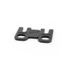
Planing for some of the upcoming task. Guide plate and rocker stud time. Is the procedure basically just loosely assemble the studs, guide plate and rockers and make sure the pushrod/rocker/valve tip alignment is good and then torque the studs? I would assume you want to also ensure these is a little pushrod to guide plate clearance as well correct?
bytor said:Planing for some of the upcoming task. Guide plate and rocker stud time. Is the procedure basically just loosely assemble the studs, guide plate and rockers and make sure the pushrod/rocker/valve tip alignment is good and then torque the studs? I would assume you want to also ensure these is a little pushrod to guide plate clearance as well correct?
Yes.....tighten the studs after you have the alignment that you want. Yes you would want
some clearance between the guide plate and the pushrod.
I found it to be a compromise trying to get everything lined up. If you are willing to take the
time, you can get something like these guides from CompCams that you weld when together
after you have the best alignment.
Don't forget to use some kind of Thread Locker on the studs.
http://www.summitracing.com/parts/CCA-4835-8/
Attachments
bytor
Well-Known Member
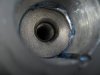
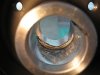
Well a bit more drama recently. Installed the harmonic balancer a few days ago and all seemed to be going well. Until I went to remove the install tool. There was a wad of metal that look like it was shaved of just about 1/2 of the hub. Not cool. Much like the broken oil ring, about craped my pants.
Took a pic and emailed Trick Flow tech support. Haven’t got a response yet and didn’t have a chance to call them today. So, I decided to remove the balancer and see what happened. It’s really weird; looks like it may have been out of round or something. The crank snout looks perfect, thank goodness. I lubed the crank and balancer well and heated the balancer in the oven for a bit before I installed it. Very strange. I’ll wait to hear from tech support.
Here's the picture once removed.
Attachments
bytor said:Well a bit more drama recently. Installed the harmonic balancer a few days ago and all seemed to be going well. Until I went to remove the install tool. There was a wad of metal that look like it was shaved of just about 1/2 of the hub. Not cool. Much like the broken oil ring, about craped my pants.
Took a pic and emailed Trick Flow tech support. Haven’t got a response yet and didn’t have a chance to call them today. So, I decided to remove the balancer and see what happened. It’s really weird; looks like it may have been out of round or something. The crank snout looks perfect, thank goodness. I lubed the crank and balancer well and heated the balancer in the oven for a bit before I installed it. Very strange. I’ll wait to hear from tech support.
Here's the picture once removed.
That's sure is a head scratcher! It looks like the balancer was made from a steel that's too soft, allowing it to roll up during installation.
Did Trick Flow make the balancer?
Where did the Blue Paint come from?
Did it seem like it was having trouble installation....a bit hard to draw it on with the tool?