TBucket Engine Project (Dart SHP)

as long as the inner edge of the head gasket is flush with or recessed slightly from the bore wall surface your fine, I generally try to have it slightly recessed but the distance won,t be critical as long as its not protruding out past the bore wall surface, on my 383 the gasket bore is just a bit over 4.063" and the bores average about 4.032"-4.034" my forged pistons have about .004 side clearance, and while not ideal it run fine for years and shows very low wear


related threads
viewtopic.php?f=53&t=726&p=8809&hilit=head+gasket+clearance#p8809

viewtopic.php?f=50&t=2681&p=6950#p6950

viewtopic.php?f=52&t=1074&p=2070&hilit=head+gasket+clearance#p2070

viewtopic.php?f=53&t=5487&p=16482&hilit=head+gasket+clearance#p16482

viewtopic.php?f=50&t=111&p=11103&hilit=head+gasket+clearance#p11103

viewtopic.php?f=50&t=1277&p=2737&hilit=copper+coat#p2737

viewtopic.php?f=50&t=501&p=9050&hilit=head+gasket+clearance#p9050
 
grumpyvette said:
as long as the inner edge of the head gasket is flush with or recessed slightly from the bore wall surface your fine, I generally try to have it slightly recessed but the distance won,t be critical as long as its not protruding out past the bore wall surface
I wasn't sure if I needed to consider growth from heat or not.

Thanks!

 
I thought they only made rings in "File to Fit", but evidently I have discovered "File to Fit" head gaskets.

After grinding them slightly larger than the bore it left a ridge that needed to be removed. Pretty much what you
would expect from copper, it's kinda gummy when you try to machine it.

The gasket bore was 4.155 - 4.125 cyl bore = .030" clearance, but this is really only .015" on each edge. My next
possible selection was 4.2" or .075/2 = .037" on each edge.

HeadGasketRemoveThisEdge_1929.jpg

.
 
Last edited:
0.030" seem correct? thats what grumpy is using he said on the post above.

gasket bore is just a bit over 4.063" and the bores average about 4.032"-4.034"
4.063 - 4.033~ = 0.030"
that is also 15 thou on each side as per Grumpy's spec above
I dont know but thats seem right on.
 
mathd said:
0.030" seem correct? thats what grumpy is using he said on the post above.

gasket bore is just a bit over 4.063" and the bores average about 4.032"-4.034"
4.063 - 4.033~ = 0.030"
that is also 15 thou on each side as per Grumpy's spec above
I dont know but thats seem right on.
That's a theoretical dimension, when you take into account ALL the tolerances, then you
might have a small portion of the gasket hanging over into the cylinder. The tolerances in the
dowel pin location, cylinder location, gasket dowel pin location and cylinder bore location can cause
a problem sometimes.......that's why I check everything I can.

It's a parameter that's hard to measure, so you have to use a visual check. Lighting, shadows, reflections
and "line of sight" can change what you perceive.....right or wrong, so I error on the safe side.

 
if your head gaskets, gasket bore was 4.155 - 4.125 cyl bore = .030" clearance, but this is really only .015" on each edge, thats almost perfect PROVIDED of course the center of the gaskets bore and cylinder bore are the same and the gaskets not significantly off set to one direction, so that the clearance on the opposite gasket allows it to hang into the bore, now its not required to be perfectly lined up, if as an example one side has the gasket edge is .018 back off from the bore and one sides just .012 thats still perfectly functional, in fact if one sides only .001 and the other gasket edge is .029 thats not ideal but I doubt it would really effect results as long as the gasket was properly installed and sealed, but in my experience those SEC gaskets are correctly machined

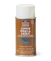
copperspray1.jpg
don,t forget to evenly spray both sides of the head gaskets and install and torque in place while tacky
 
grumpyvette said:
copperspray1.jpg

don,t forget to evenly spray both sides of the head gaskets and install and torque in place while tacky
I see on the can that I have it says "Wait 30 seconds between coats to allow surface to become tacky".

Do you put a second coat on ??? How long after the last coat do you have to install and torque gasket.....a few minutes
or say 15 minutes. Just curious what time frame I'm working with.
 
Ive had zero problem spraying and installing within 4-5 minutes but I don,t think waiting a bit longer , like 7-10 minutes and using a second coat , then just waiting 2 minutes untill it started to get tacky would hurt anything, the spray gasket sealant forms a micro layer , between gasket and block or gasket and cylinder head ,that seals minor scratches and imperfections and prevents coolant leaks
 
With over 1900 pictures so far, you would think I would have a picture of how this came apart. I did have all these pieces in zip lock bag together, but I wanted confirmation if someone knows that the picture below is correct.

The sleeves fit nicely inside the piston and they also fit the end of the spring.


PressureReliefValve_1936.jpg


.
 
Last edited:
file.php


thats a good question, BTW Ive never seen TWO spacers, Ive seen a single spacer ,like you show but not twin spacers, if I saw that ID call the manufacturer and just ask if it was supposed to be like that or was that an assembly mistake, because the piston must be pushed back far enough to allow oil to bleed off thru the bye-pass before the spring stacks solid or the pressure relief won,t function and with two spacers that might not work correctly?
its always best to ask questions of the manufactures tech guys because they should be able to provide you with an answer, and assuming you just can assemble things or trust that it was assembled correctly at the factory is not always the best route to maintaining durability
 
Good idea....checking with Melling about having two spacers. I was so focused on whether I was going to assemble the pieces in the right sequence that completely missed what you pointed out.

BTW, I'm starting to clean and prepare for final assembly. Also the rotating assembly is out to be balanced now, dropped it off last Friday.


DorianL said:
Getting exciting!!!!!!
The nice 70F weather today is not helping me to keep my smile under control ! :D


grumpyvette said:
yes! looking forward to that first tires smoking burn out
I do so hope that it is tire smoke and not some other kind! :)

 
Indycars said:
DorianL said:
Getting exciting!!!!!!
The nice 70F weather today is not helping me to keep my smile under control ! :D


grumpyvette said:
yes! looking forward to that first tires smoking burn out
I do so hope that it is tire smoke and not some other kind! :)

Oh the uncontrollable smile again, dont get too evil with the burnout because that smile won't get off for a while :D
I also hope there is no other kind of smoke me too. obviously.
 
I talked with George Richmond at Melling today. After explaining the spacer
sleeves, he said they don't use any spacers. I offered to email him a
picture like the one below. His reply to my email is below in the red text.

I wonder if there is some way to test the pressure at which the valve is going
to regulate my pressure before assembling the engine???


Email response from Melling:

Those sleeves are not anything we use.

The valve and spring looks correct.


George Richmond
Technical Services Manager
ASE Master Automotive Technician

Melling Tool Company
2620 Saradan Drive
Jackson, MI 49202
517-787-8172 Ext 134

PressureRegulatorValve_1936.jpg

.
 
Last edited:
PLEASE READ THE LINKS FIRST, as the info will help you get a better grasp on how things work
viewtopic.php?f=54&t=3536

viewtopic.php?f=54&t=6479

viewtopic.php?f=54&t=1257&p=2704&hilit=shimming+pump#p2704

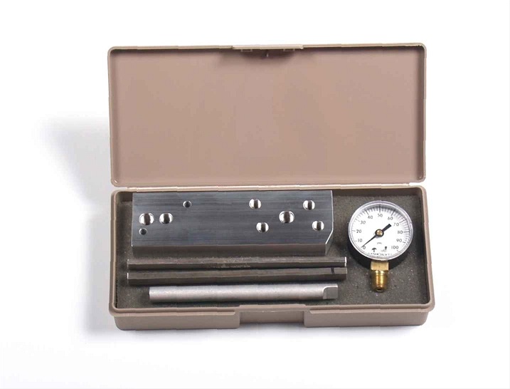
I can,t see that fabricating a oil pump tester costing more than $40,
if you think about it its basically a aluminum plate with a few precisely located holes drilled in it a few threaded, too allow the gauge and pump mounting and a $10 pressure gauge
pumptes.jpg

I have all the components in stock I just need to go out too the shop measure carefully a half dozen times and use the drill press or mill and Ill have a new test tool in a few minutes after I get time to fabricate this
 
Last edited by a moderator:
grumpyvette said:
I have all the components in stock I just need to go out too the shop measure carefully a half dozen times and use the drill press or mill and Ill have a new test tool in a few minutes after I get time to fabricate this
Great.....how long do you think it will take you to get to Oklahoma after your finished? :cool:

To simplify, could I just put 1/4" plate with the holes shown to determine the pressure at which the valve is going to regulate at.


TestFixture_884.jpg

.
 
Last edited:
Im reasonably sure it could be made to function but holding the pump and running the drill and reading the gauge at the same time might be a problem and Im assuming your using a second pump body as the test tool so the bye-pass clearances might be slightly different than the actual pump and the component clearances being different the results you'll be getting will be very slightly different "
 
Back
Top