Busterrm,
I had already had a couple of coats on the pan, so I didn't go back the strip it again for the 2nd time. The block may be a different story, we'll see.
-----------------------------------------------------------------------------------------
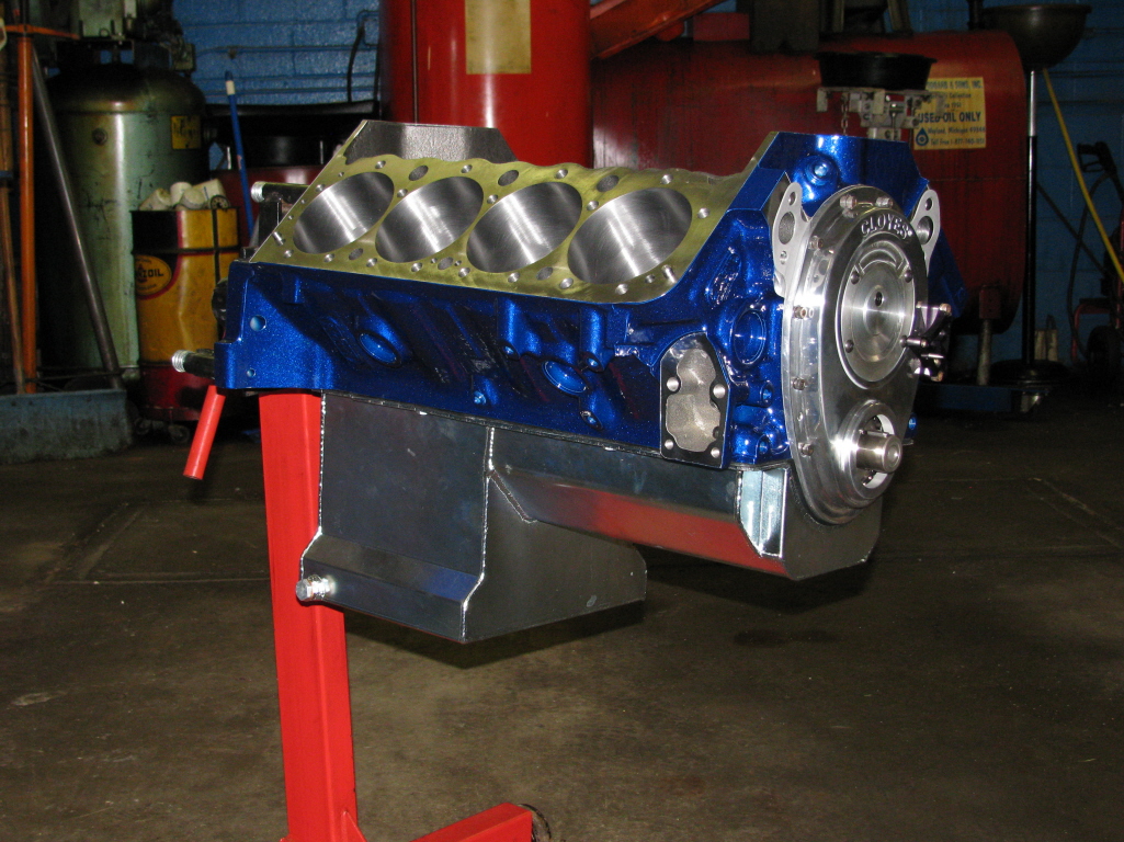
After all the gold iridate was gone, I used the Por15 Marine Clean and then their Prep & Ready. The paint seems to have good adhesion now.
I was still having problems with junk in the paint when I was done, mainly on the top surfaces. So I thought it was stuff in the air, but after I started straining the paint thru the filter shown below it was much better.

I may still go back and color sand down to 2500 grit, not sure yet.


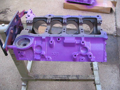
Time to start working on the block!
.
I had already had a couple of coats on the pan, so I didn't go back the strip it again for the 2nd time. The block may be a different story, we'll see.
-----------------------------------------------------------------------------------------
After all the gold iridate was gone, I used the Por15 Marine Clean and then their Prep & Ready. The paint seems to have good adhesion now.
I was still having problems with junk in the paint when I was done, mainly on the top surfaces. So I thought it was stuff in the air, but after I started straining the paint thru the filter shown below it was much better.
I may still go back and color sand down to 2500 grit, not sure yet.
Time to start working on the block!
.
Last edited: